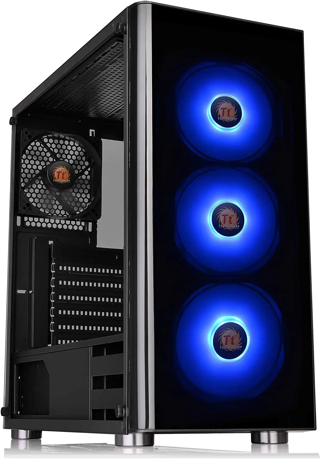
Thermaltake Tempered Glass RGB Edition Mid-Tower Chassis
Specification
Model Versa J25 TG Versa J25 TG RGB
Case Type Middle tower
Dimension(H*W*D) 461 206 402 mm
(18.1 x 8.2 x 15.8 inch)
Side Panel 3 mm Tempered Glass x 1
Material SPCC
Cooling System Rear (exhaust): 120 x 120 x 25 mm fan (1000 rpm, 16 dBA) Rear (exhaust): 120 x 120 x 25 mm fan (1000 rpm, 16 dBA) Front (Intake) : 120 x 120 x 25 mm RGB fan (1000 rpm, 16 dBA) x 3
Drive Bays – Accessible- Hidden 2 x 2.5”(HDD Bracket) 2 x 3.5” or 2 x 2.5”(HDD Tray)
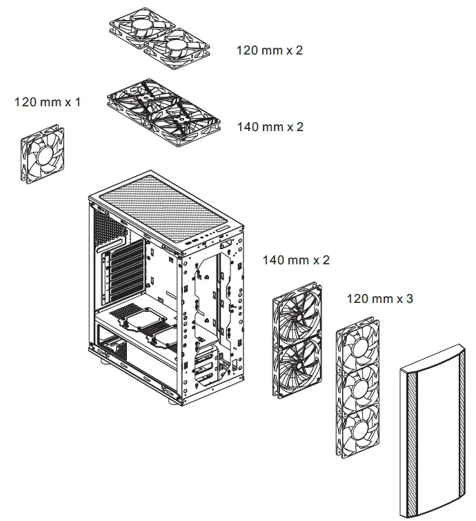
Fan Support Front: 3 x 120 mm, 2 x 140 mm Top: 2 x 120 mm, 2 x 140 mm Rear: 1 x 120 mm
Radiator Support Front: 1 x 360 mm Rear: 1 x 120 mm
Clearance CPU cooler height limitation: 160 mm VGA length limitation: 330 mm PSU length limitation: 160 mm
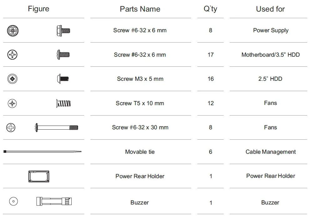
Accessory
Warning and Notice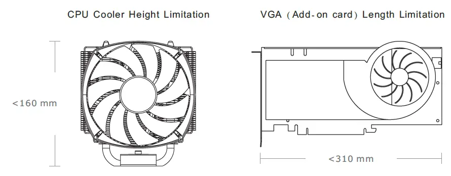
Warning!!
- Height limit for the CPU heatsink:
- The height limit for the CPU heatsink is 160 mm (6.3 inches).
- Length limit for the VGA (graphics card):
- The length limit for the VGA (graphics card) is 310 mm (12.2 inches).
Side Panel Disassembly
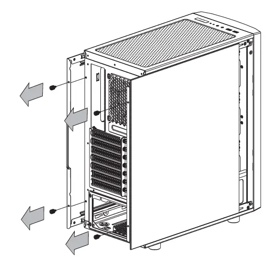
Remove the screws on the back of the chassis, and open the side panel.
PSU Installation
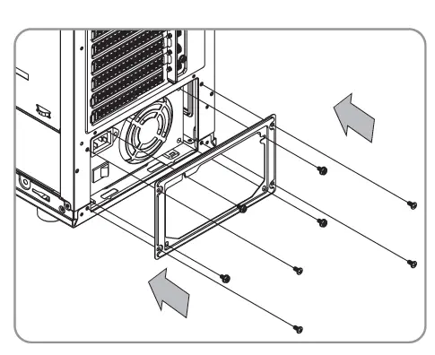
Place the power supply in proper location and secure it with screws.
Motherboard Installation
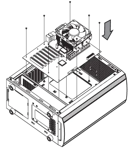
- Lay down the chassis.
- Install the motherboard in proper location and secure it with screws.
3.5” & 2.5” HDD Installation
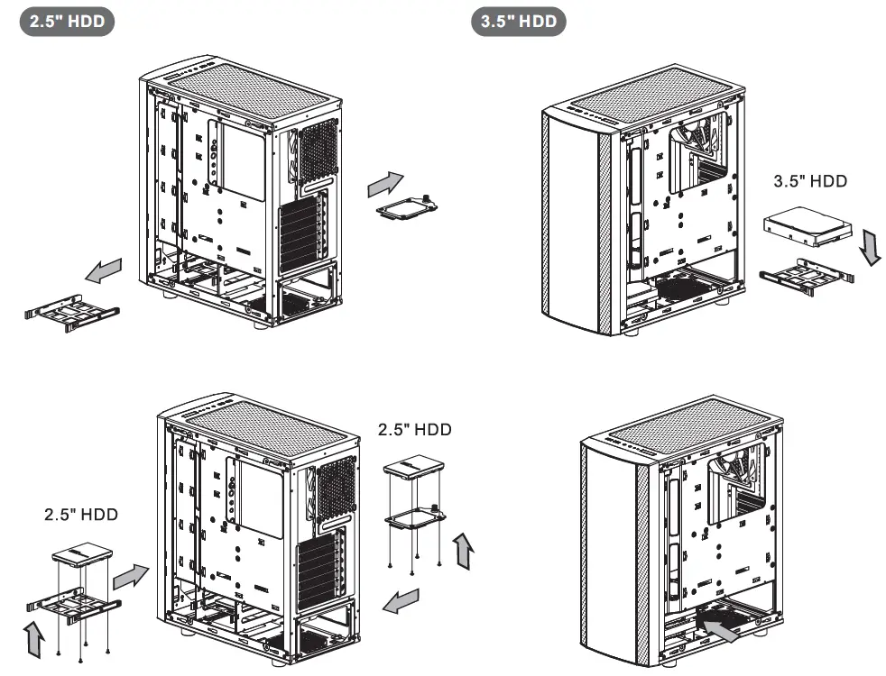
Insert the HDD and tighten it with the screws.
PCI Slot Usage
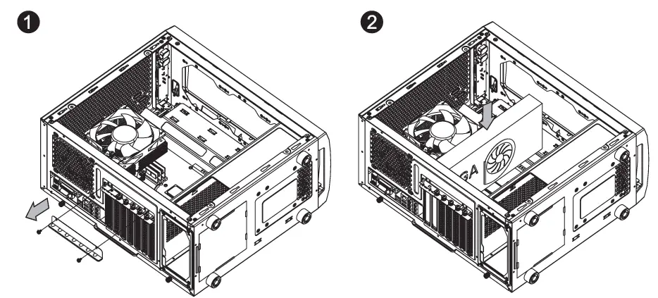
- Loosen the screws with a screwdriver.
- Install the PCI card in proper location and secure it with screws.
RGB Switch Mode ( RGB Edition only)
RGB Lighting Mode 1
Single Color Mode 2~8 (Red, Yellow, Green, Cyan, Blue, White, Purple)
Breath Mode Mode 9~15 (Red, Yellow, Green, Cyan, Blue, White, Purple)
Light Off Mode 16
Long press on RGB button for 3 seconds , fans will blink red light twice which now are controlled by MB software. And vice versa.
How to connect MB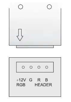
Air Cooling Installation
Radiator Installation
The radiator is applicable up to 40 mm high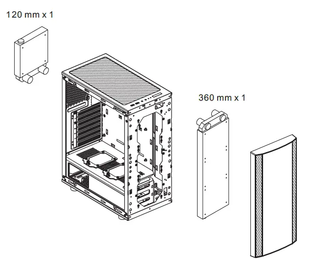
Leads Installation
Leads Installation Guide
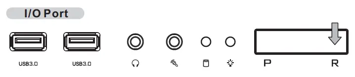
Case LED Connection On the front of the case, you can find some LEDs and switch leads. Please consult your user manual of your motherboard manufacturer, then connect these leads to the panel header on the motherboard.
USB 3.0 connection
- Make sure your motherboard supports USB 3.0 connection.
- Connect the USB 3.0 cable to the available USB 3.0 port on your computer.
Audio Connection Please refer to the following illustration of Audio connector and your motherboard user manual. Please select the motherboard which used AC’97 or HD Audio(Azalia),(be aware of that your audio supports AC’97 or HD Audio (Azalia)) or it will damage your device(s).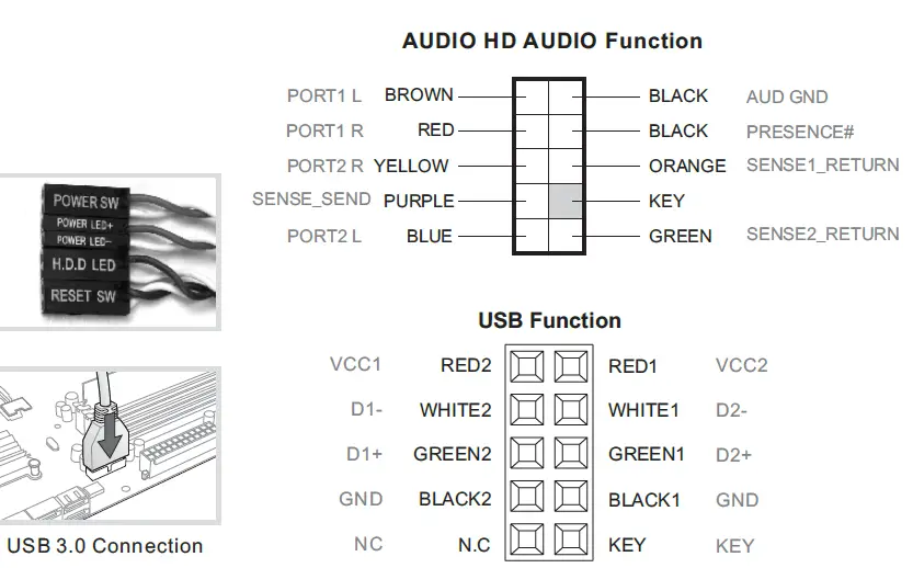
Thermaltake Power Supply Series (Optional)
What is Smart Pwer Management (SPM)?
Smart Power Management is a cloud-based software that seamlessly integrates three intelligent platforms- DPS G PC APP 3.0, DPS G Smart Power Management Cloud 1.0 and DPS G Mobile APP 1.0 and Complies key statistics about your pc into detailed charts and breakdowns for your instant PC status view and management. With easy access to SPM through your Pc or more devices, whether you are outside or indoors, enjoy taking full control of your build anytime, anywhere!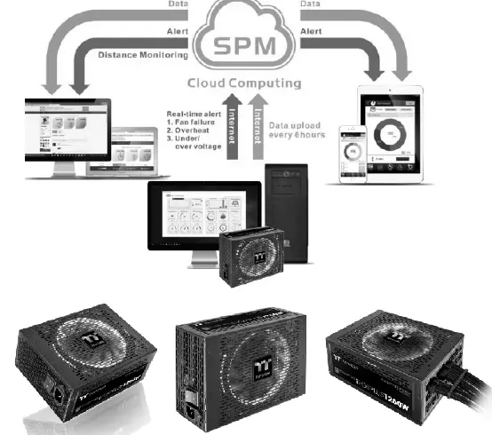
Thermaltake has several Power supply product lines; please refer to our official website and Facebook Fan page for more detail information!
Brand official website:
http://www.thermaltake.com/
Global Facebook:
http://www.facebook.com/ThermaltakeInc
Taiwan Facebook:
http://www.facebook.com/thermaltakeTW![]()


