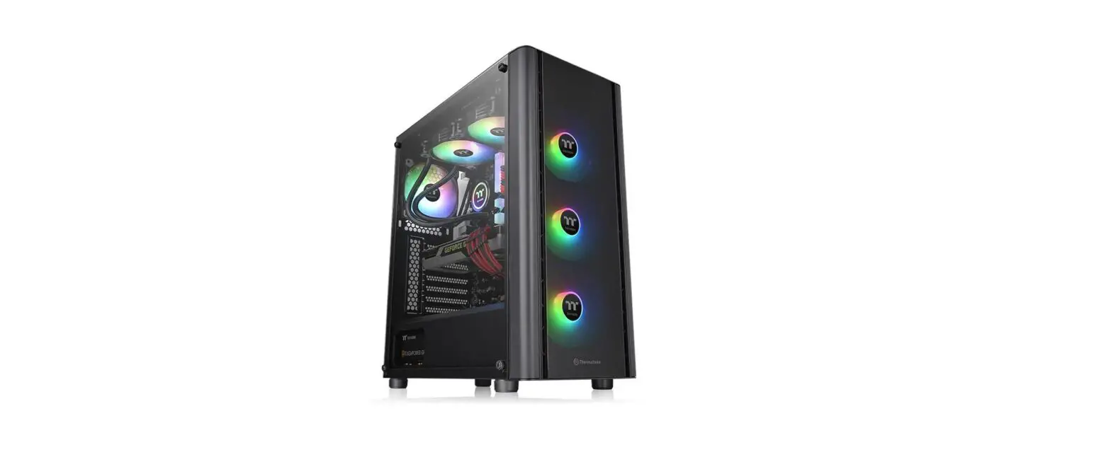
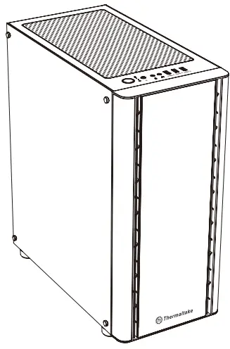
thermaltake V250 TG ARGB Tempered Glass ARGB Mid Tower Chassis User Manual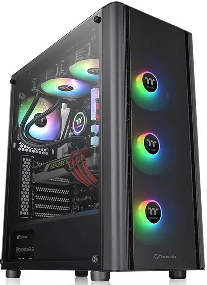
SPECIFICATION
- Model: V250 TG ARGB
- Case Type: Middle towe
- Chassis Dimension (H*W*D:430 x 216.5 x 477 mm (16.9 x 8.52 x 18.78 inch)
- Side Panel: 4mm Tempered Glass x 1
- Cooling System: Rear(exhaust): 120 x 120 x 25 mm fan (1000 rpm, 16 dBA) x 1 Front(intake): 120 x 120 x 25 mm Addressable RGB fan (1000 rpm, 27.2 dBA) x
- Drive Bays Accessible Hidden: 2 x 3.5“ or 2 x 2.5” (HDD Rack) 2 x 2.5” (HDD Bracket)
- Expansion Slots: 7
- Motherboards: 6.7” x 6.7” (Mini ITX), 9.6” x 9.6” (Micro ATX), 12” x 9.6” (ATX)
- I/O Port: 1 x USB 3.0, 2 x USB 2.0, 1 x HD Audi R Button , 1 x
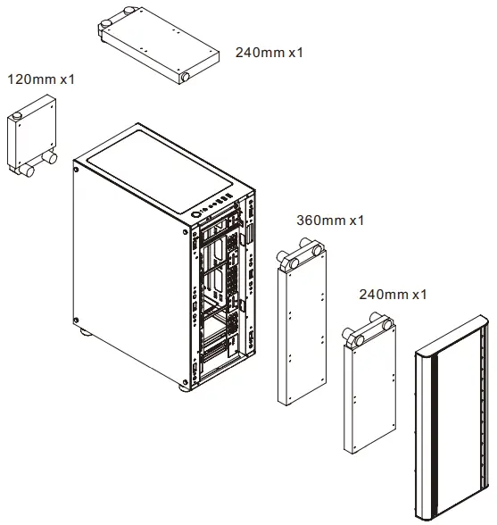
- Fan Support: Front: 3 x 120 mm, 2 x 140 mm Top: 2 x 120 mm, 2 x 140 mm Rear: 1 x 120 mm
- Radiator Support: Front: 1 x 280 mm, 1 x 360 mm Top: 1 x 240 mm Rear: 1 x 120 mm
- Clearance: CPU cooler height limitation: 160 mm VGA length limitation: 320 mm PSU length limitation: 160mm(With HDD Rack), 200mm(Without HDD Rack)
ACCESSORY
| Figure | Parts Nam | Q’ty | Used for |
| Screw M3 x 5mm | 25 | Motherboard / 2.5” SSD | |
| Screw #6-32 x 5mm | 8 | 3.5” HDD | |
| Screw #6-32 x 15mm | 2 | 3.5” HDD Lock | |
| Screw #6-32 x 6mm | 6 | Power / VGA | |
| Stand-off #6-32 x 6mm | 3 | Motherboard | |
| Screw T5 x 12mm | 12 | Case Fan | |
| Screw #6-32 x 30mm | 8 | Case Fan | |
| Cable Tie | 10 | Cable Management | |
| Buzzer | 1 | Motherboard Alarm |
WARNING AND NOTICE
- CPU Cooler Height Limitation

- VGA (Add-on card) Length Limitation

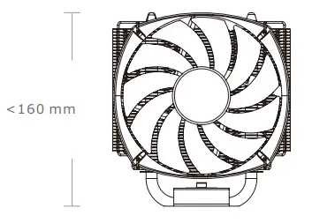
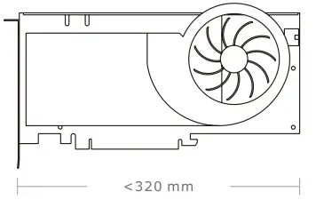
Warning!!
CPU Cooler Height Limitation: Please ensure that your CPU cooler does NOT exceed 160 mm (6.3 inches) height. VGA (Add-on card) Length Limitation: Please ensure that your VGA (Add-on card) does NOT exceed 320 mm (12.6 inches) length.
Side Panel Disassembly
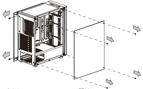
Remove the screws on the back of the chassis, and open the side panel.
PSU INSTALLATION
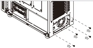
Place the power supply in proper location and secure it with screw
Motherboard Installation
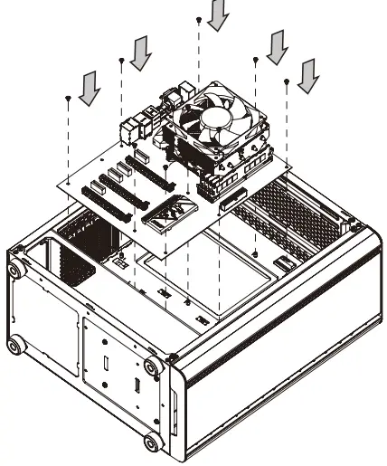
- Lay down the chassis.
- Install the motherboard in proper location and secure it with screws.
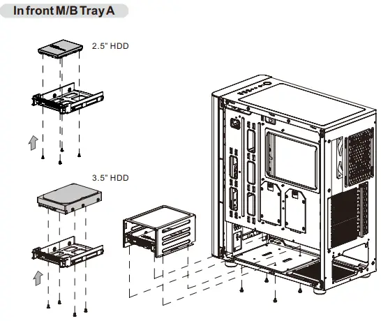
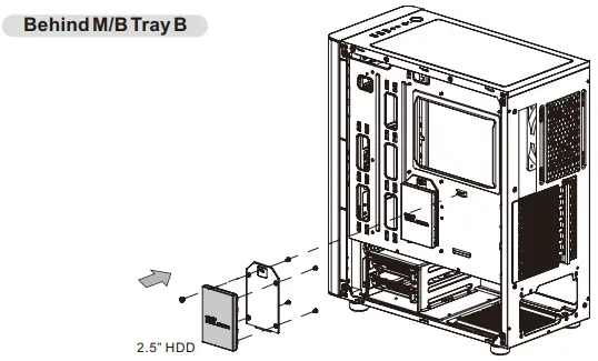
3.5″ & 2.5″ HDD Installation
- In front M/B Tray A

- Behind M/B Tray B

PCI Slot Usage
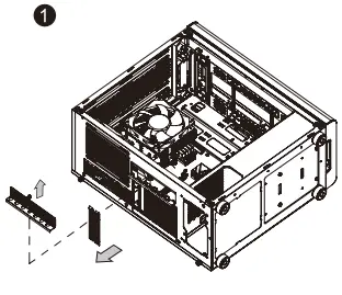
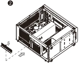
- Loosen the screws with a screwdriver.
- Install the PCI card in proper location and secure it with screws.
RGB Switch Mode
I/O Port
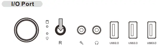
- Wave Mode: Mode 1
- Flow Mode: Mode 2
- RGB Lighting: Mode 3 (Single Color)
- Radar Mode: Mode 4~10 (Red, Yellow, Green, Cyan, Blue, White, Purple)
- Breath Mode: Mode 11~18 (RGB, Red, Yellow, Green, Cyan, Blue, White, Purple)
- Full Lighted Mode: Mode 19
- Single Color: Mode 20~26 (Red, Yellow, Green, Cyan, Blue, White, Purple)
- Light Off: Mode 27
Long press on RGB button for 3 seconds, fan will blink twice which now are controlled by MB software. And vice versa.
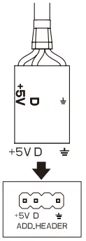
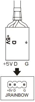
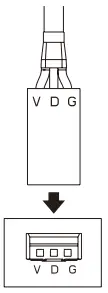
How to connect MB
- ASUS
Aura Addressable Strip Header(s)
- MSI
JRGB-strip Header(S)
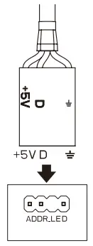
- ASROCK
Addressable RGB LED Header(s)
- GIGABYTE
AORUS RGB Fusion with Digital LEDs
Air Cooling Installation
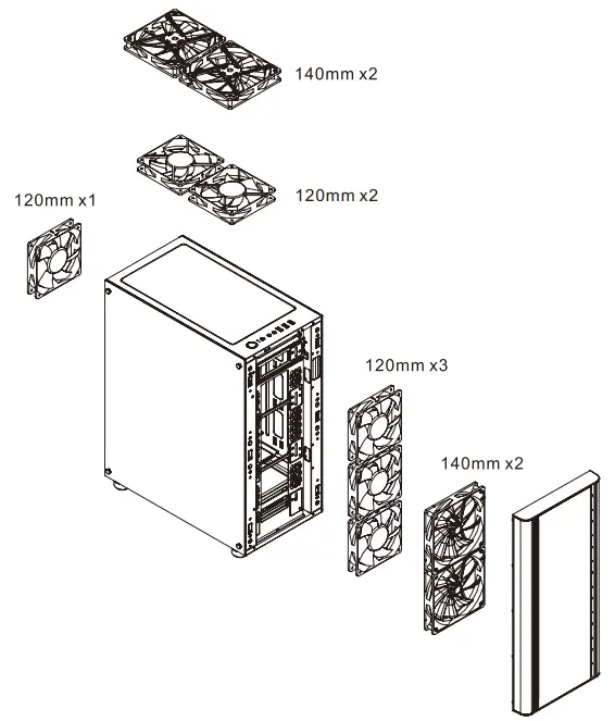
Radiator Installation
Leads Installation
Leads Installation Guide
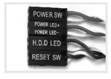
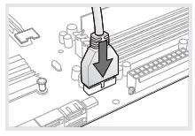
Case LED Connection / On the front of the case, you can find some LEDs and switch leads. Please consult your user manual of your motherboard manufacturer, then connect these leads to the panel header on the motherboard.
USB 2.0 Connection /
Please consult your motherboard manual to find out the section of “USB connection”.
USB 3.0 connection /
- Make sure your motherboard supports USB 3.0 connection.
- Connect the USB 3.0 cable to the available USB 3.0 port on your computer.
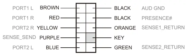
Audio Connection / Please refer to the following illustration of Audio connector and your motherboard user manual. Please select the motherboard which used AC’97 or HD Audio(Azalia),(be aware of that your audio supports AC’97 or HD Audio (Azalia)) or it will damage your device(s).

AUDIO HD AUDIO FUNCTION
USB FUNCTION

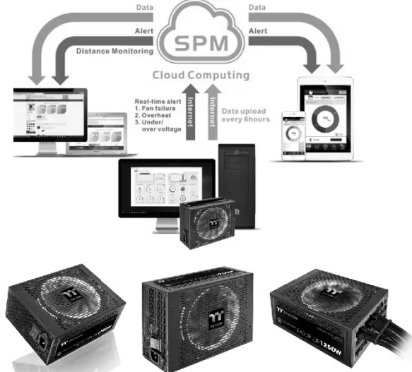
Thermaltake Power Supply Series (Optional)
What is Smart Power Management (SPM)?
Smart Power Management (SPM) is a cloud based software that seamlessly integrates three intelligent platforms — DPS G PC APP 3.0, DPS G Smart Power Management Cloud 1.0 and DPS G Mobile APP 1.0 — and compiles key statistics about your PC into detailed charts and breakdowns for your instant PC status view and management. With easy access to SPM through your PC or mobile devices, whether you are outside or indoors, enjoy taking full control of your build anytime, anywhere!
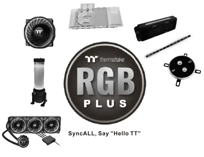
Tt RGB Plus Ecosystem
- Tt RGB Plus Software Thermaltake’s patented software to synchronize TT RGB PLUS products with addressable LEDs.

- Tt Al Voice Control Give you full control over the TT RGB PLUS products with your voice.


CUSTOMER SUPPORT
Thermaltake has several power supply product lines; please refer to our official website and Facebook Fan Page for more detail information! Brand official website: http://www.thermaltake.com/ Global Facebook :https://www.facebook.com/Thermaltakeinc Taiwan Facebook https://www.facebook.com/ThermaltakeTW