
DETEX V40 Value Series Battery Alarmed Rim Exit Device

overview
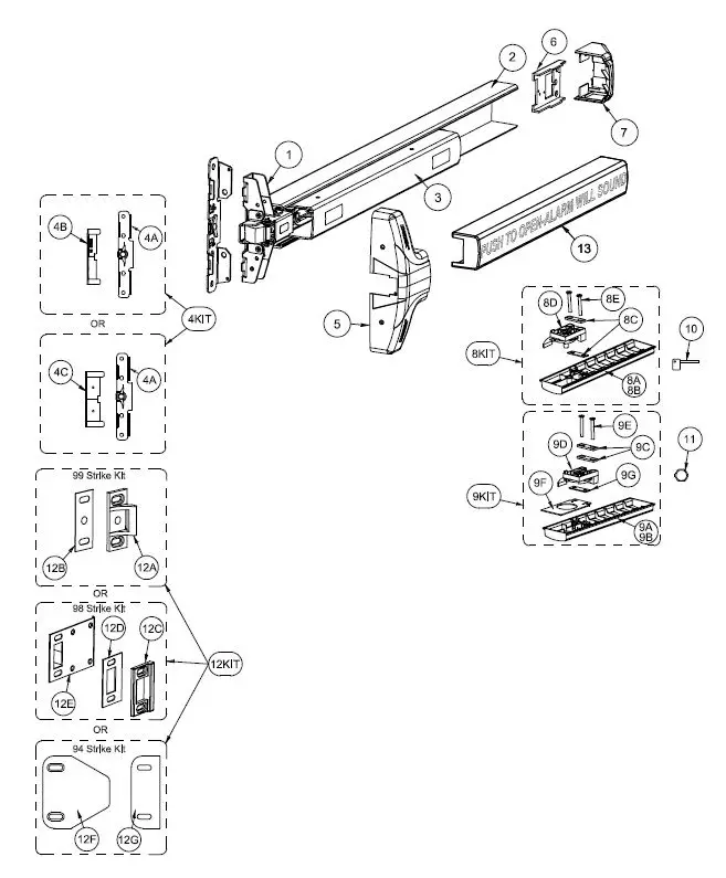
| PARTS BREAKDOWN | ||
| Item | Order Part# | Description |
| 100698-5 | Centercase Assembly, Narrow Stile, V40 series | |
|
2 | 106281 | Baseplate Extrusion, 36″, Silver |
| 106285 | Baseplate Extrusion, 48″, Silver | |
| 106289 | Baseplate Extrusion, 36″, Black | |
| 106290 | Baseplate Extrusion, 48″, Black | |
| 3 | 103065-1 | Pushpad Subassembly, 36″ |
| 103065-2 | Pushpad Subassembly, 48″ | |
| 4KIT | 103806-1 | Mounting Plate/Strike Locator Kit, Narrow Stile, 98 Strike BP2 (includes 4A & 4B) |
| 103806-3 | Mounting Plate/Strike Locator Kit, Narrow Stile, 99 Strike, BP2 (includes 4A & 4C) | |
| 4A | 100696-1 | Mounting Plate, BP2, Narrow Stile |
| 4B | 101899 | Strike Locator 2″ Glass Door (98) |
| 4C | 100212 | Strike Locator, Standard (99) |
| 5 | 101805-1 | Centercase Cover, V40 series |
| 6 | 101844-1 | Endcap bracket w/o battery holder |
| 101844 | Endcap bracket w/ battery holder | |
| 7 | 101822 | Endcap |
| SKIT | 101803-1 | Fillerplate, Subassembly, S&R, Hex Dogging, HD, V40 series, 36″ (includes 8A or 8B through 8E) |
| 8A | 101812-1 | Fillerplate, HD, 36″ |
| 8B | 101812-2 | Fillerplate, HD, 48″ |
| 8C | 100164 | Spacer, dogging bracket, .120″ thick |
| 80 | 102216-4 | Die cast dogging assembly, HD |
| BE | PP-5802-124 | Screw, mach, 10-32 x 1-1/2″ PFH |
| 9KIT | 102195-1 | Fillerplate, Subassembly, S&R, Cylinder Dogging, CD, V40 series, 36″ (includes 9A or 9B through 9G) |
| 9A | 102194-1 | Fillerplate, CD, 36″ |
| 9B | 102194-2 | Fillerplate, CD, 48″ |
| 9C | 100164 | Spacer, dogging bracket |
| 90 | 102216-3 | Die cast dogging assembly, CD |
| 9E | PP-5802-124 | Screw, mach, 10-32 x 1-1/2″ PFH |
| 9F | 102196 | Bracket, fillerplate, V40, CD |
| 9G | 100938 | Spacer, dogging bracket, .060″ thick |
| 10 | 100450 | Hex Key (for Hex Dogging) |
| 11 | 100783 | Cylinder Nut (for Cylinder Dogging) |
| 12KIT | 100855-2 | 99 Strike Kit (includes 12A & 12B) |
| 100855-1 | 98 Strike Kit (includes 12C, 120 & 12E) | |
| 102212-1 | 94 Double Door Strike Kit (includes 12F & 12G) | |
| 12A | 100234-1 | Strike, Non-roller |
| 12B | 100088 | Strike Shim |
| 12C | 100480 | Strike, Mortise |
| 120 | 100482 | Shim, Mortise Strike |
| 12E | 100481 | Shield, Strike |
| 12F | 102211 | Double Door Strike Plate |
| 12G | 102214 | Shim, 94 strike |
| 13 | 105417-1 | Pushpad Wrap, 36″, Red (English text) |
| 105417-2 | Pushpad Wrap, 48″, Red (English text) | |
| 105417-3 | Pushpad Wrap, 36″, Black | |
| 105417-4 | Pushpad Wrap, 48″, Black | |
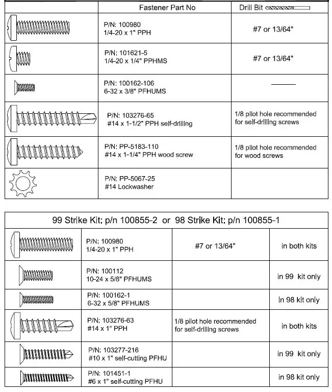
Hardware Table for BASIC device mounting.Additional hardware is provided per the device configuration in kit form and is addressed on the appropriate pages as required
- Device hardware kit: p/n 101809-2 for
- Hex Dogging (HD) Device
- hardware kit: p/n 101809-5 for
- Cylinder Dogging (CD)

Tools Required:
- Phillips & small flat Screw Drivers
- Combination Square
- Center Punch
- Saw for cutting device if necessary (chop saw preferred)
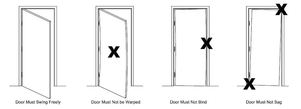
!!!CHECK BEFORE STARTING!!!
- Wide Stile (Surface Strike)
- Minimum door stile 4-1/2″ (114 mm) Template drawings provide door and frame structural and dimensional specifications for door and frame preparation.
- Narrow Stile
- Minimum door stile 2″ (51 mm)
- Surface strike possible
- Mortise strike recommended
- Doors and frames with walls having a structural thickness (metal skin plus reinforcement, or solid wood) to engage less than (3) full screw threads, are considered unreinforced for hardware.
- Unreinforced Doors: Use Sex Nuts and Bolts
- Unreinforced Frames: Use Blind Rivet Nuts (see sketch)
- Fasteners for unreinforced openings are not supplied by Detex.
- Reinforced door or frame engages at least (3) screw threads.

NOTE:
750mm MAXIMUM DOOR WIDTH OPENING FOR EUROPE FOR 36″ DEVICE(1000mm MAXIMUM DOOR WIDTH OPENING FOR EUROPE FOR 48″ DEVICE)THE SAFETY FEATAURES OF THIS PRODUCT ARE ESSENTIAL TO ITS COMPLIANCE WITH EN 1125. NO MODIFICATION OF ANY KIND, OTHER THAN THOSE DESCRIBED IN THESE INSTRUCTIONS ARE PERMITTED.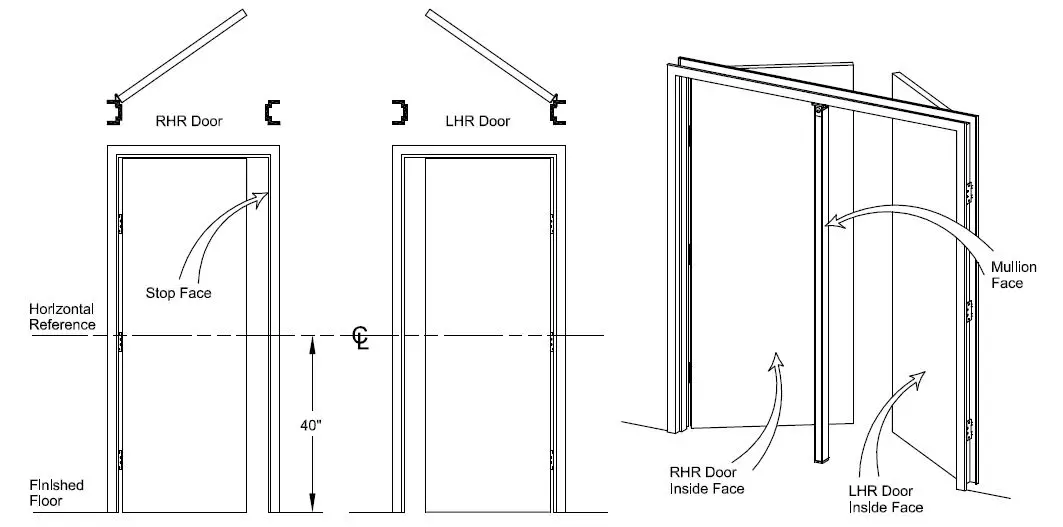
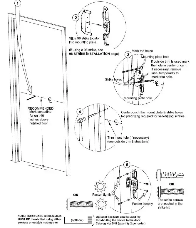
MOUNTING PLATE & STRIKE INSTALLATION:
DEVICE INSTALLATION:
NOTE: If device is too long, refer to next page for cut-down procedure.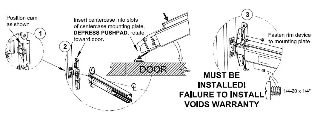
With push pad assembly level, secure the endcap bracket to door by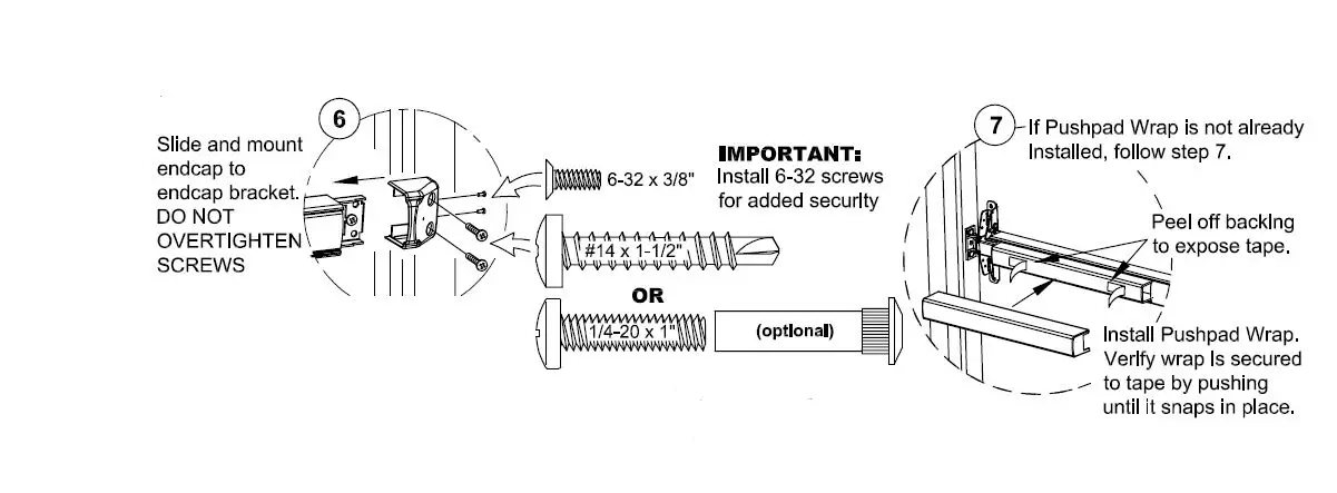
Align the 99 strike with the latch bolt. \_VFirmly tighten screws (shim if needed)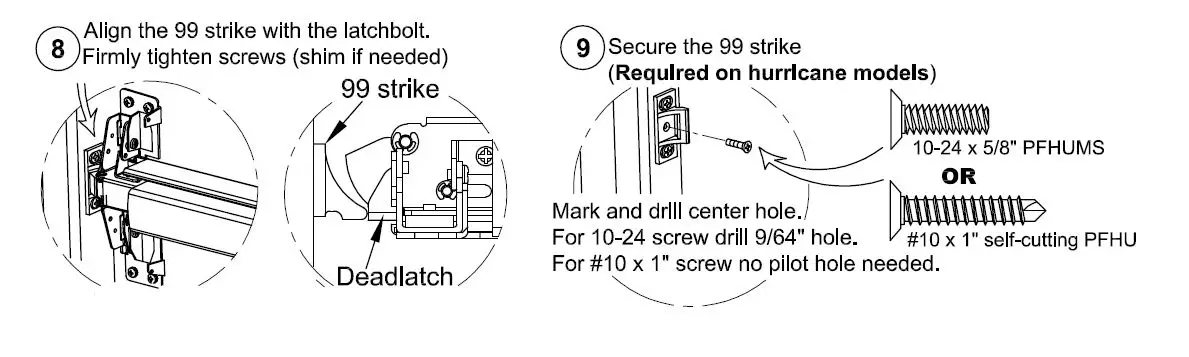
Check device function and strike engagement BEFORE going to step 9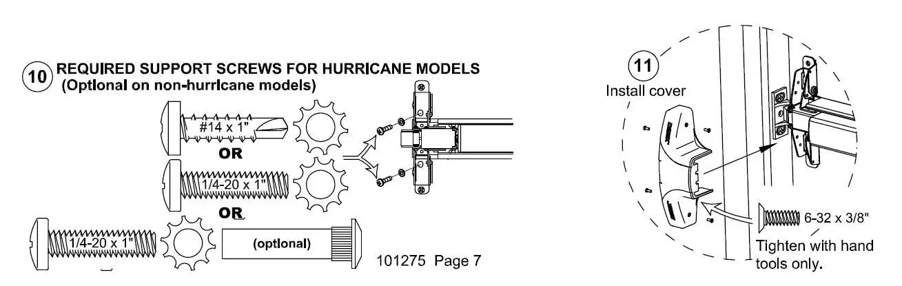
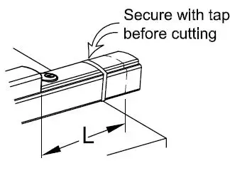
CHECKING FOR DEVICE CLEARANCE (Cut-Off procedure if required) 
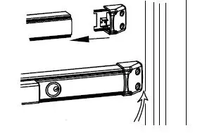
- Slide endcap assembly onto the extrusion

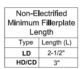
- Cut filler plate and extrusion STRAIGHT & SQUARE to

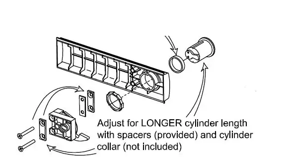
MORTISE CYLINDER INSTALLATION (if required)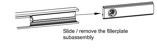
1/4″ collar (not supplied) required for 7 pin cylinder. (Detex p/n: ECL-1595)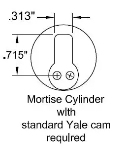
- All cylinder spacers must be used.
- ) Tum key max CCW before installing slide in fillerplate.
- Reinstall fillerplate subassembly

98 STRIKE INSTALLATION (not approved for Hurricane models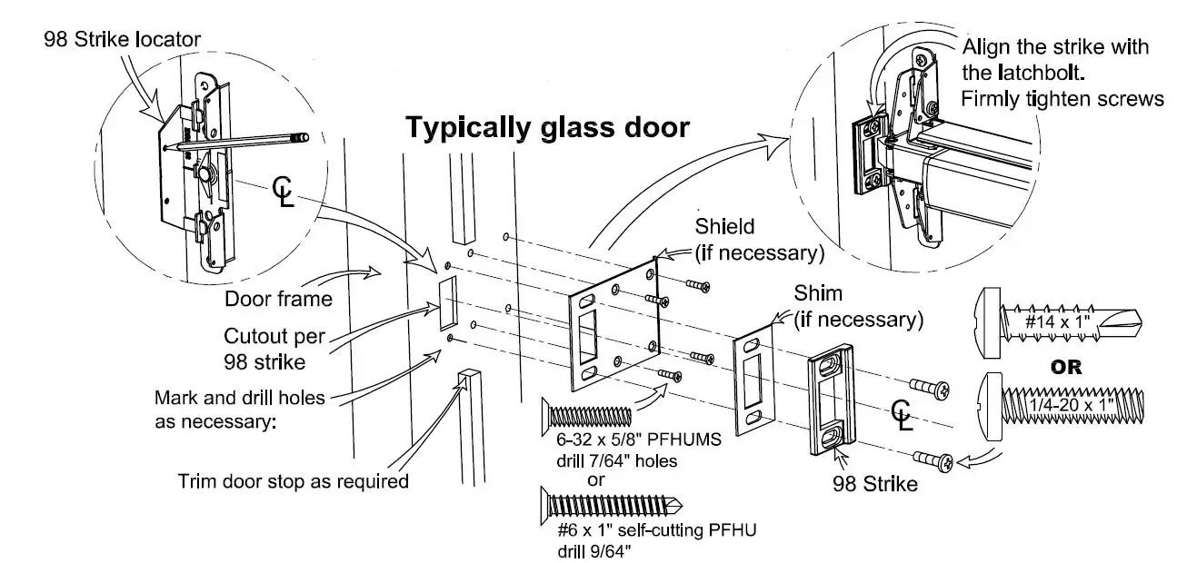
STRIKE HOOK INSTALLATION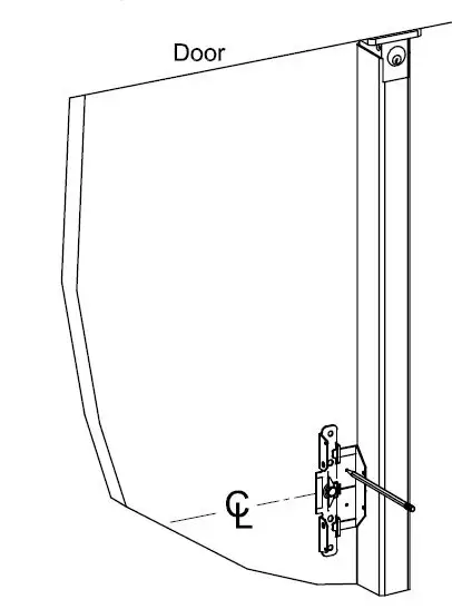
trike mounting locator hole (template) locations provided.use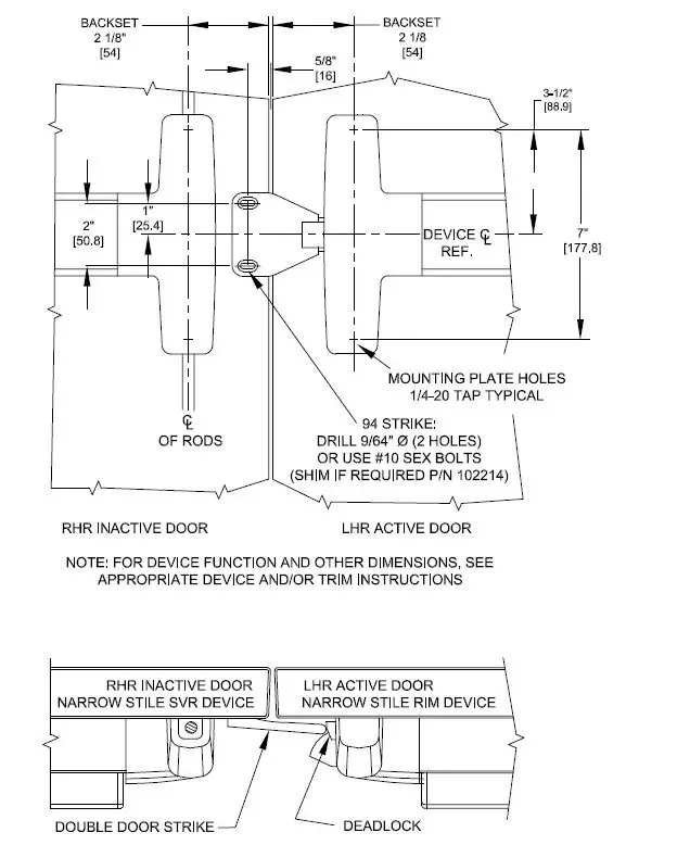
Narrow Stile Endcap Mounting Plate Fascia (p/n 101864) (For use on Glass Doors)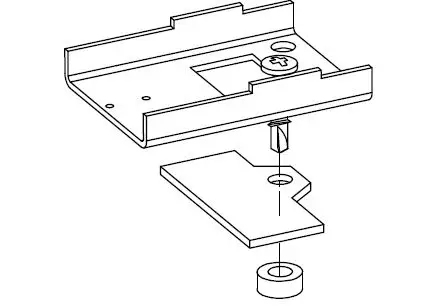
THE DEVICE USED ON THE ACTIVE DOOR SHOULD BE INSTALLED SO THAT THE STRIKE WILL DEPRESS THE DEADLOCK SUFFICIENTLY TO ALLOW FOR ANY AND ALL ALARM / ELECTRONIC FUNCTIONS.ADD SHIM (P/N 102214) AS REQUIRED. TWO PROVIDED IN KIT. THE INACTIVE DOOR SHOULD CLOSE FIRST.
Optional Accessories 
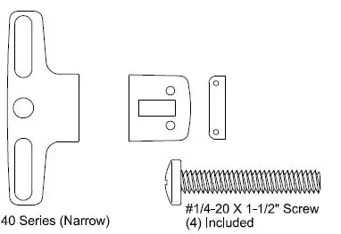
- The #1/4-20 kit is available in (4) finishes:
- Catalog No: SN1 Brushed Brass
- BHMA 606 Finish Catalog No: SN1
- Oil Rubbed Bronze BHMA 613
- Finish Catalog No: SN1 Brushed Chrome
- BHMA 626 Finish Catalog No: SN1 Stainless Steel
- BHMA 630 Finish

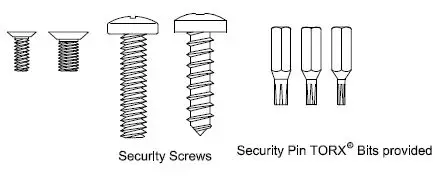
Tamper Kit
p/n: Catalog (Security 101233 No: Kit) SSK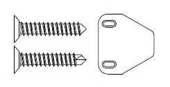
Key Stop Kit
p/n: Catalog 101867 No: KS wrench Requires (not a .05 hex include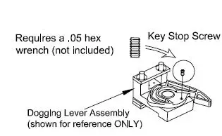
Cylinder nut socket kit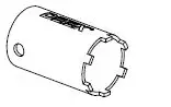
The suffixed following with Models 01, 02, in 03, the 08, series 09, or were 14 evaluated allowed by C, UL: CN, D, Controlled DN, DT, Exit ONT, Panic DU, Devices; DNU, P, Model PN, W 10 or and WS, 40. These followed by devices BP1, may BP2, RHR or BP3, LHR, BP5, followed BP6, by BP7or EA, BP8 which fo may llowed be by 605, followed 606, by LD 611, or 612, CD, 613, followed 625, by 626, 605, 628, 606, 629, 611, 630, 612, 693, 613, 695 625, or 711 626, fo628, allowed 629, by the 630, 693, 695 or 711 followed by 98 or 99, followed by 36 or 48.


