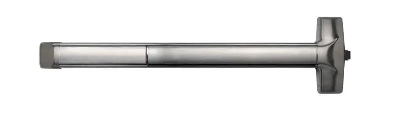
DETEX F10-40 Series Rim Exit Device

overview
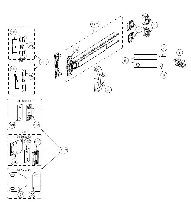
| PARTS BREAKDOWN | ||
| Item | Order Part# | Description |
| 1KIT | 105500-63 | Centercase/Pushpad SubAssembly, 40 series, 36″, 630 (includes 1A) |
| 105500-62 | Centercase/Pushpad SubAssembly, 10 series, 36″, 630 (includes 1A) | |
| 1A | 100698-1 | Centercase Assembly, Narrow Stile, 40 series |
| 100698-2 | Centercase Assembly, Wide Stile, 10 series | |
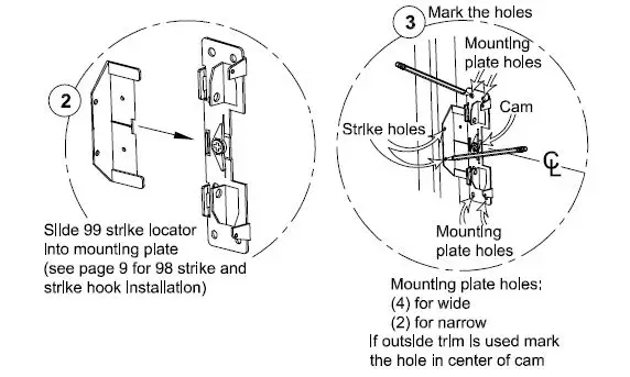
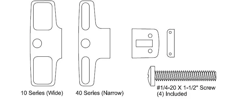
| 2KIT | 103806-1 | Mounting Plate/Strike Locator Kit, Narrow Stile (includes 2A & 2C) |
| 103806-2 | Mounting Plate/Strike Locator Kit, Wide Stile (includes 2B & 2D) | |
| 2A | 100696-1 | Mounting Plate, BP2, Narrow Stile |
| 2B | 100697-1 | Mounting Plate, BP1, Wide Stile |
| 2C | 101899 | Strike Locator 2″ Glass Door (98) |
| 2D | 100212 | Strike Locator, Standard (99) |
|
3 | 100311-9 | Centercase Cover, Stainless Steel, Narrow, 40 series, 630 |
| 100196-9 | Centercase Cover, Stainless Steel, Wide, 10 series, 630 | |
| 104602-1 | Centercase Cover, Aluminum, Narrow, 40 series, 628 | |
| 104640-1 | Centercase Cover, Aluminum, Wide, 10 series, 628 | |
|
4 | 100147 | Endcap bracket for EC1 (ramped) endcap w/o battery holder |
| 101093 | Endcap bracket for EC1 (ramped) endcap w/ battery holder | |
| 104303 | Endcap bracket for EC2 (flush) endcap w/o battery holder | |
| 104636 | Endcap bracket for EC2 (flush) endcap w/ battery holder | |
| 5 | 101642-9 | Endcap, EC1 (ramped) Stainless Steel, 630 |
| 104304-9 | Endcap, EC2 (flush) Stainless Steel, 630 | |
| 104612-1 | Endcap, EC2 (flush) Aluminum, 628 | |
|
6 | 100860-54 | Fillerplate, Subassembly, S&R, Hex Dogging, HD, 10 series, 36″, 630 |
| 100860-49 | Fillerplate, Subassembly, S&R, Cylinder Dogging, CD, 10 series, 36″, 630 | |
| 100860-100 | Fillerplate, Subassembly, S&R, Hex Dogging, HD, 10 series, 36″, 628 | |
| 100860-137 | Fillerplate, Subassembly, S&R, Hex Dogging, HD, 40 series, 36″, 628 | |
| 7 | 100450 | Hex Key (for Hex Dogging) |
| 8 | 100783 | Cylinder Nut (for Cylinder Dogging) |
| 9 | 102216-2 | Hex Dogging Assembly |
| 102216 | Cylinder Dogging Assembly | |
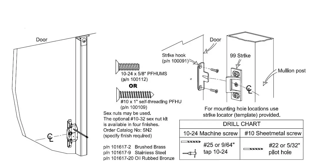
| 10KIT | 100855-2 | 99 Strike Kit (includes 10A & 10B) |
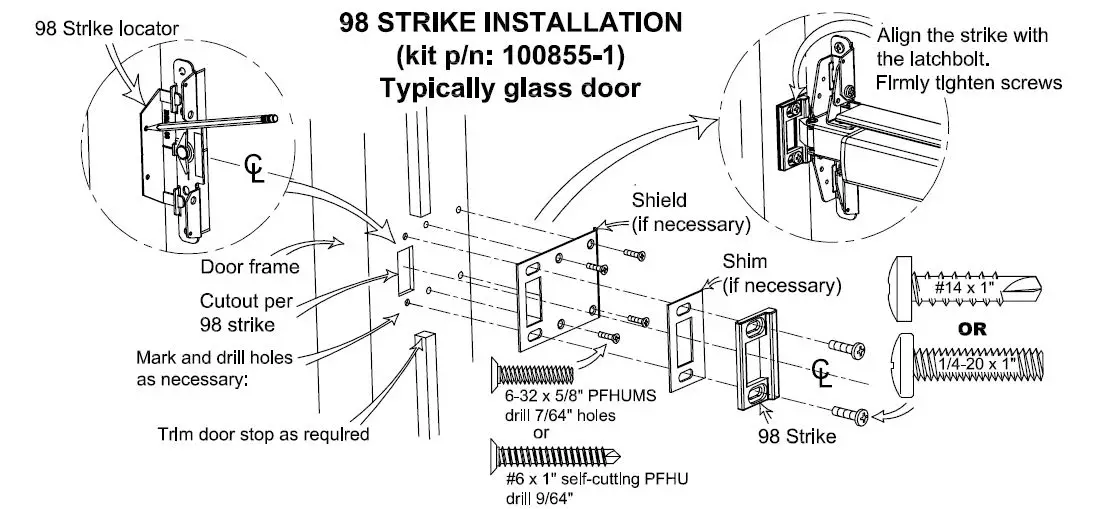
| 100855-1 | 98 Strike Kit (includes 10C, 10D & 10E) | |
| 102212-1 | 94 Double Door Strike Kit (includes 10F & 10G) | |
| 10A | 100234-1 | Strike, Non-roller |
| 1OB | 100088 | Strike Shim |
| 10C | 100480 | Strike, Mortise |
| 1OD | 100482 | Shim, Mortise Strike |
| 10E | 100481 | Shield, Strike |
| 10F | 102211 | Double Door Strike Plate |
| 10G | 102214 | Shim, 94 strike |
Hardware Table for BASIC device mounting.
Additional hardware is provided per the device configuration in kit
form and is addressed on the appropriate pages as required EC1 (ramped) Device hardware kit: p/n 101438-1 for Hex Dogging (HD) EC1 (ramped) Device hardware kit: p/n 101438-2 for Cylinder Dogging (CD) EC2 (flush) Device hardware kit: p/n 105723-1 for Hex Dogging (HD)
EC2 (flush) Device hardware kit: p/n 105723-2 for Cylinder Dogging (CD)
99 Strike Kit: p/n 100855-2 or 98 Strike Kit: p/n 100855-1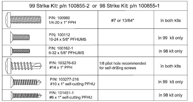
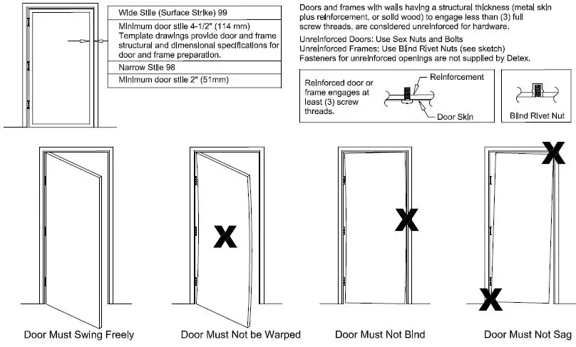
!!!CHECK BEFORE STARTING!!! 
NOTE:
750mm MAXIMUM DOOR WIDTH OPENING FOR EUROPE FOR 36″ DEVICE1000mm MAXIMUM DOOR WIDTH OPENING FOR EUROPE FOR48″ DEVICETHE SAFETY FEATURES OF THIS PRODUCT ARE ESSENTIAL TO IT’S COMPLIANCE WITH EN 1125. NO MODIFICATION OF ANY KIND, OTHER THAN THOSE DESCRIBED IN THESE INSTRUCTIONS ARE PERMITTED.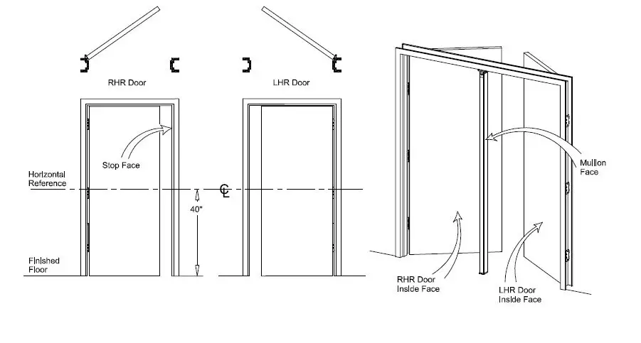
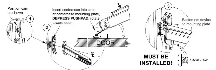
DEVICE INSTALLATION:
NOTE: If device is too long, refer to next page for cut-down procedure.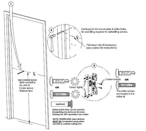
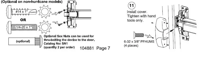
REQUIRED SUPPORT SCREWS FOR HURRICANE MODELS (Optional on non-hurricane models) 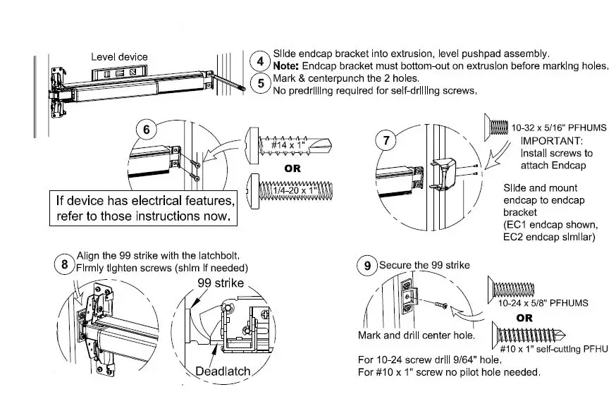
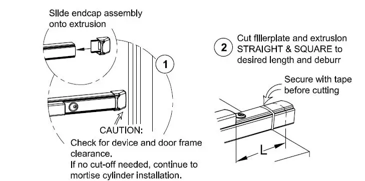
CHECKING FOR DEVICE CLEARANCE (Cut-Down procedure if required) 
For aluminum Advantex finish cutdown applications:
After cutting, the baseplate extrusion can be reversed to place the cut end inside the head cover. To do so, loosen the setscrew inside the aluminum baseplate extrusion and slide extrusion out, reverse, & slide back in. Tighten setscrew.
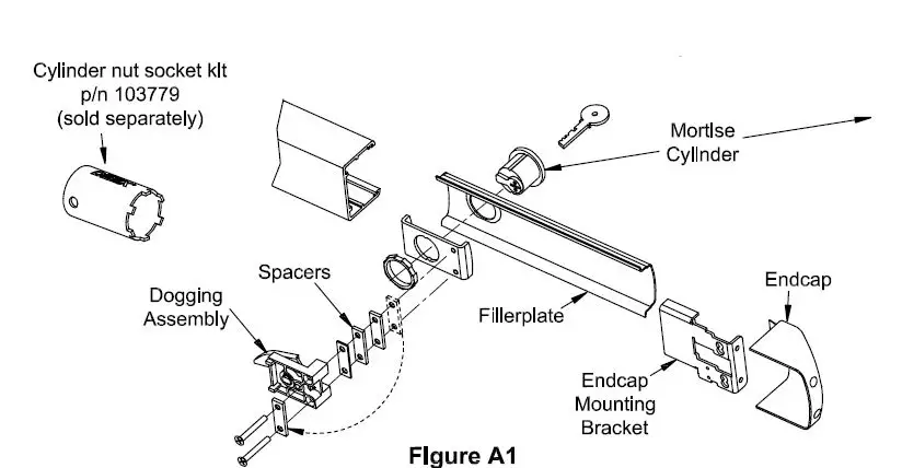
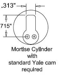
MORTISE CYLINDER INSTALLATION 
Follow steps “a” through “g” for CD installations
- Remove endcap and endcap mounting bracket.
- Remove fillerplate.
- Remove and discard shipping insert and nut. Loosen (2) screws from dogging assembly.
- Install mortise cylinder (sold separately) with large hex nut provided.
- Trial fit dogging assembly. If cylinder is too short, remove spacers as necessary and reattach them under the (2) screw heads (See Figure A 1 ). Fasten the (2) screws to the rest of the assembly.
- Rotate key counterclockwise
- Assembly complete. Continue with Panic Hardware instruction.


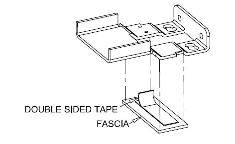
- Narrow Stile Endcap Mounting Plate Fascia (For use on Glass Doors) (not used with EC2 endcap)

- Remove the endcap mounting bracket.
- Attach the fascia with the adhesive tape.
- Re-attach the endcap mounting bracket.

94 DOUBLE DOOR STRIKE INSTALLATION (if required)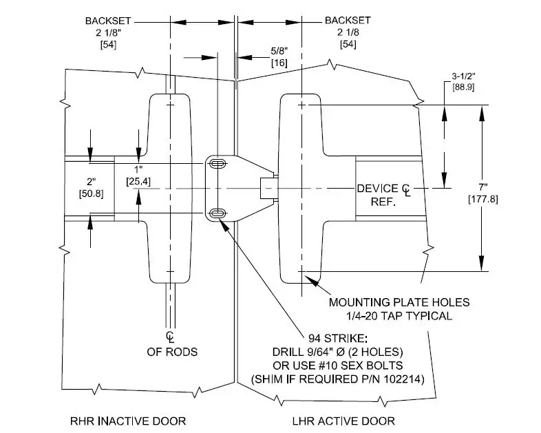
NOTE:
FOR DEVICE FUNCTION AND OTHER DIMENSIONS, SEE APPROPRIATE DEVICE AND/OR TRIM INSTRUCTIONS 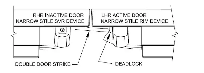
THE DEVICE USED ON THE ACTIVE DOOR SHOULD BE INSTALLED SO THAT THE STRIKE WILL DEPRESS THE DEADLOCK SUFFICIENTLY TO ALLOW FOR ANY AND ALL ALARM / ELECTRONIC FUNCTIONS.
ADD SHIM (P/N 102214) AS REQUIRED. TWO PROVIDED IN KIT.THE INACTIVE DOOR SHOULD CLOSE FIRST.
Optional Accessories 
Glass Bead Kit
- Catalog No: GB1 – Glass Bead Kit, 10 series p/n: 101643
- Catalog No: GB2 – Glass Bead Kit, 40 series p/n: 101644
Sex Nut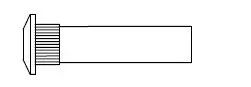
The #1/4-20 kit is available in (4) finishes:
- Catalog No: SN1 Brushed Brass BHMA 606 Finish
- Catalog No: SN1 Oil Rubbed Bronze BHMA 613 Finish
- Catalog No: SN1 Brushed Chrome BHMA 626 Finish
- Catalog No: SN1 Stainless Steel BHMA 630 Finish
Tamper Kit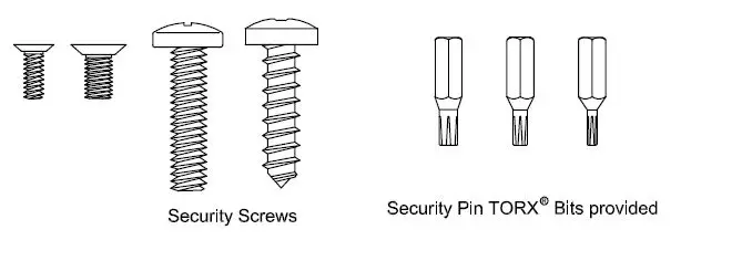
Double Door Strike Kit
Catalog No: 94 (includes shim & screws) screws ptn: 102212-1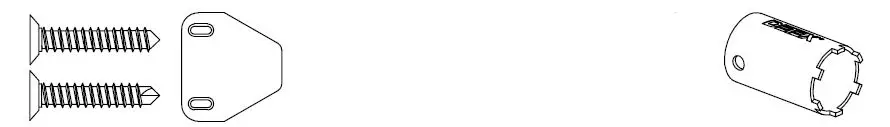
The following Models in the series were evaluated by UL: Controlled Exit Panic Devices; Model 10 and 40. These devices may be suffixed with 01, 02, 03, 08, 09, or 14 followed by C, CN, D, DN, DT, ONT, DU, DNU, P, PN, W or WS, followed by BP1, BP2, BP3, BP5, BP6, BP7or BPS followed by 605, 606, 611, 612, 613, 625, 626, 628, 629, 630, 693, 695 or 711 followed by the RHR or LHR, followed by EA, which may be followed by LD or CD, followed by 605, 606, 611, 612, 613, 625, 626, 628, 629, 630, 693, 695 or 711 followed by 98 or 99, followed by 36 or 48.


