resideo VBG26, MR6 Braukmann
APPLICATION
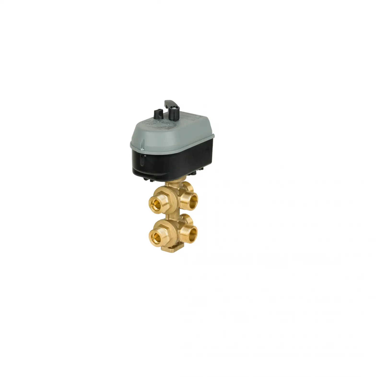
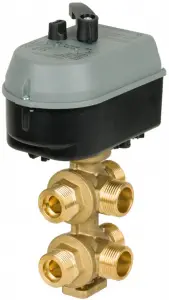
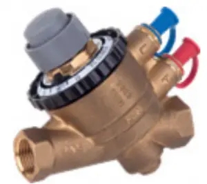
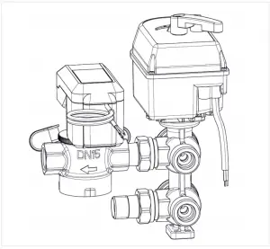
VBG26 ball valves are designed as change-over valve to connect one 2-pipe heat exchanger (Fan-coil Unit or Ceiling) to the 4-pipe system, ideally together with the Kombi-FCU Pressure Independent Control Valve used for dynamic balancing.
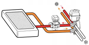
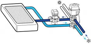
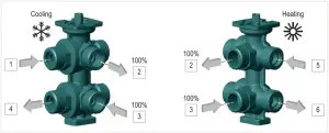
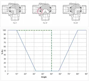
The simultaneous rotation of two balls, mechanically connected to the one stem, opens supply and return ways on one side (e.g. cooling) and closes at the same time the other side (heating). That avoids any mixing between flows and reduce potential energy losses.
VBG26 valves are delivered with flow limiter kit in the valve box. That gives flexibility in flow rate adjustment by picking adequate limiter disk with Kv value displayed on. Each Kv value should be written during installation on the label stripped on the valve neck.
VBG26 valves are designed to be actuated by MR6 rotary valve actuators in two types. On/off actuator gives the basic change-over functionality, modulating enables setting mid position to close the valve. Position feedback on modulating actuator shell be used for remote system monitoring and system check.
SPECIAL FEATURES
- Change-over Valve with scalable flow limitations covering all flow needs with only 3 valve versions
- In combination with modulating actuator option to close the valve in mid-position
- Externally threaded valve versions for easier installation
- Optional use of on/off or modulating actuator
- Modulating actuator with position feedback
- Pre-wired actuator with clear position indication and manual operation
- Can be combined with the Kombi-FCU for high accurate flow control; Ideal connection for 4-pipe systems including hydronic dynamic balancing
INSTALLATION EXAMPLE
VALVES VBG26
Technical Data
| Controlled medium: | Chilled or hot water according to VDI2035 with up to 50 % Glycol (oxygen concentration less than 0.2 g/m3, pH 8. 9.5; Fe<0.5 mg/kg; Cu<0.1 mg/ kg). |
| Pressure values | |
| Nominal pressure rating: | PN16 |
| Max. differential pressure: | 2bar |
| Operating temperatures | |
| Media temperature: | +2°…+110° |
| Ambient temperature: | 0°…+55° |
| Specifications | |
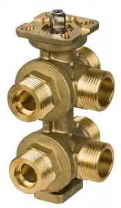
| Valve type: | 6-way ball valve, change over |
| Leakage rate: | Class A as per EN12266-1/ 12 – P12 |
| Total operation angle: | 90° |
| First side operation angle : | 0…32° |
| “Dead zone” operation angle: | 32°…58° |
| Second side operation angle: | 58°…90° |
| Flow characteristic: | linear |
| Connection/Sizes | |
| Connection type: | External BSPP, flat sealing |
CONSTRUCTION
| Overview | ||
 | ||
| Components | Materials | |
1 | Material body | Brass |
| Not depicted components: | ||
| Inner parts | Brass | |
| O-rings | EPDM, PTFE, FKM | |
| Packaging | Separate unit pack | |
TECHNICAL CHARACTERISTICS
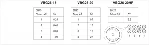
kvs-Values
DN size | Kv max: | Kv flow limitation: | Ordering Number |
15 | 1.25 | 0.25 / 0.40 / 0.63 /1 | VBG26-15 |
20 | 2.8 | 0.7 / 1.0 / 1.6 / 2.1 | VBG26-20 |
| 20 | 4.0 | 2.5 | VBG26-20F |
Flow limiters by kv disks
VBG26 valves are supplied with the maximum flow rate defined by Kv max value.
As there is typically heating flow much lower comparing to cooling one the valve should be adjusted on the flow rate. VBG26 valves are delivered with flow limiter kit in the valve box. That gives flexibility in flow rate adjustment by picking adequate kv disk with Kv value displayed on. Each Kv value should be written during installation on the label stripped on the valve neck.
Port connections
VBG26 valves are designed with integrated pressure relief functional device.
That integrated device prevents systems from potential damages caused by pressure changes when the valve is close (45°) and ambient temperate could heat-up or cooldown close circuit.
The integrated pressure relief device balance potential overpressure in the coils side with the main system pressure when VBG26 valve closes the coil circuit (up to rotations 50°).
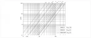
Pressure drop characteristics
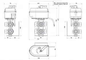
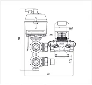
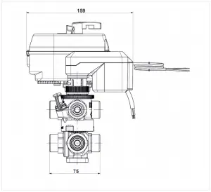
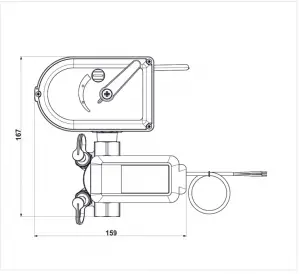
DIMENSIONS
Valves
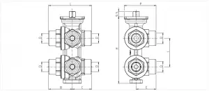
| Parameter | Values | ||
| Nominal size diameter: Connection Dimensions: | DN | 15 | 20 |
D | G 3/4″ | G 3/4″ | |
B | 41.5 | 47 | |
C | 33.8 | 39 | |
E | 35 | 41 | |
G | G 3/4″ | G 3/4″ | |
H | 117 | 141 | |
I | 50 | 60 | |
P | 55.9 | 62 | |
L | 75.3 | 86 | |
ORDERING INFORMATION
Options
| Description: | DN: | O.S. no. : |
| 6-way valve; external threads, kv max 1.25; flow limiters 0.25/0.40/0.63/1.00 | DN15 | VBG26-15 |
| 6-way valve, external threads, kv max 2.8; flow limiters 0.7/1.0/1.6/2.1 | DN20 | VBG26-20 |
| 6-way valve, high flow; externals thread, kv max 4.00; flow limiter 2.5 | DN20 | VBG26-20HF |
Accessories
| Description | Part No. | |
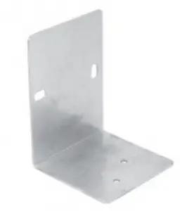 | Fastening Base for VBG26 | |
| VBG26-063ZA | ||
 | Insulation shell | |
| Insulation shell for DN15 type | VBG26-063GI-15 | |
| Insulation shell for DN20 types | VBG26-063GI-20 | |
 | Pliers for KV Disks | |
| VBG26-091SOS | ||
Suggested PICV for dynamic balancing
 | V5006TY; DN15, DN20 | |
| V5006TYxxx | ||
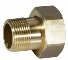 | Piping to connect VBG26 to V5005TY DN15 | |
| ACS-15T |
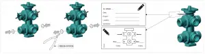
INSTALLATION GUIDELINES
Mounting
For more-detailed information on mounting, see the Mounting Instructions supplied with each valve.
Please strictly follow flow direction and port connection guidance. Cooling side must be connected to ports “1” and “4”!
The water quality must meet VDI 2035 requirements with max 50% of Glycol.
TRANSPORTATION AND STORAGE
Keep parts in their original packaging and unpack them shortly before use.
The following parameters apply during transportation and storage:
| Parameter | Value |
| Environment: | clean, dry and dust free |
| Min. ambient temperature: | – 20 °C |
| Max. ambient temperature: | 70 °C |
| Min. ambient relative humidity: | 0 % * |
| Max. ambient relative humidity: | 55 % * |
*non condensing
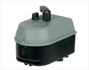
ACTUATOR MR6
Technical Data
| Operating temperatures | |
| Ambient temperature: | 1 °C…+55 °C |
| Media temperature: | -2 °C +110 °C |
| Specifications | |
| Actuator type: | Rotary actuator for VBG26 |
| Power supply: | 24 VAC+/-15 %, 50 Hz |
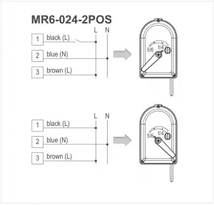
| Control signal: | ON/OFF (MR6-24-2POS); modulating (MR6-24-010) |
| Power consumption: | see “Actuator types” |
| Nominal torque: | 8 Nm |
| Operating humidity range: | 0 %…80 %, non-condensing |
| Runtime: | 75 sec/90° |
| Nominal operation angle: | 90° |
| Cable specification: | 1 m fixed cable, 3×0.5 mm2; crimped |
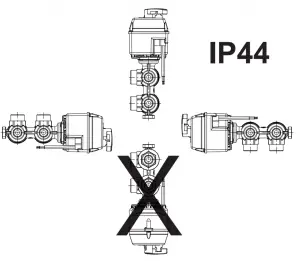
| IP Rating / Protection degree: | IP44 |
| Environmental conditions: | For use in home (residential, commercial, and light- industrial) environments |
| Protection class: | II |
| Approvals: | CE |
ORDERING INFORMATION
Options
O.S. no. | Power supply | Control signal | Power consumption | Cable | ||
Driving | Holding | |||||
| W | VA | W | ||||
MR6-24-2POS | 24 VAC ±15 %; 50 Hz | on/off | 3.0 | 3.0 | relay ON 0.6W relay OFF 0W | 3 x 0.5 mm2 1m length |
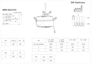
MR6-24-010 | 24 VAC ±15 %; 50 Hz | modulating 0 – 10 VDC, 4 – 20 mA Input impedance: 26kΩ (position signal Y) | 2.5 | 2.5 | 0.3 | 4 x 0.5 mm2 1m length |
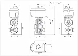
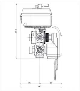
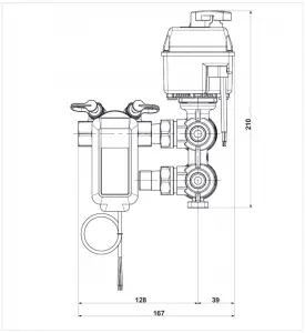
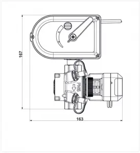
DIMENSIONS
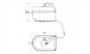
MR6 with VBG26-15
MR6 with VBG26-20/20HF
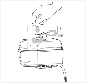
INSTALLATION GUIDELINES
Mounting
For more-detailed information on mounting, see the Mounting Instructions supplied with each valve.
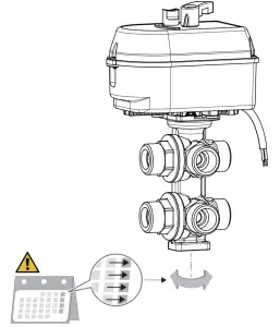
Recommendation: Turn the valve actuator at least once a week to avoid sticking the valve in one position
VBG26-15 with Kombi-FCU DN15 (connected via ACS-15T)
Option 1
Option 2

Electrical Installation
Manufactured for and on behalf of Pittway Sàrl, Z.A., La Pièce 4,
1180 Rolle, Switzerland
For more information
homecomfort.resideo.com/europe
Ademco 1 GmbH, Hardhofweg 40,
74821 MOSBACH, GERMANY
Phone: +49 6261 810
Fax: +49 6261 81309

© 2020 Resideo Technologies, Inc. All rights reserved.


