![]() Backflow Preventers
Backflow Preventers
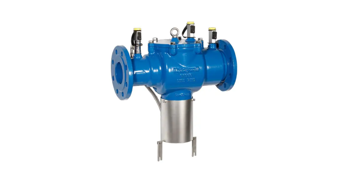
Braukmann BA300
Backflow Preventer
with flanged connections

APPLICATION
Backflow preventers of this type are suitable for the protection of drinking water systems against back pressure, backflow, and back-siphonage.
The backflow preventer protects drinking water for fluids up to and including liquid category 4 to EN 1717.
They can be used for residential buildings, industrial and commercial purposes within the scope of their specification.
The powder-coated ductile iron housing provides increased corrosion protection.
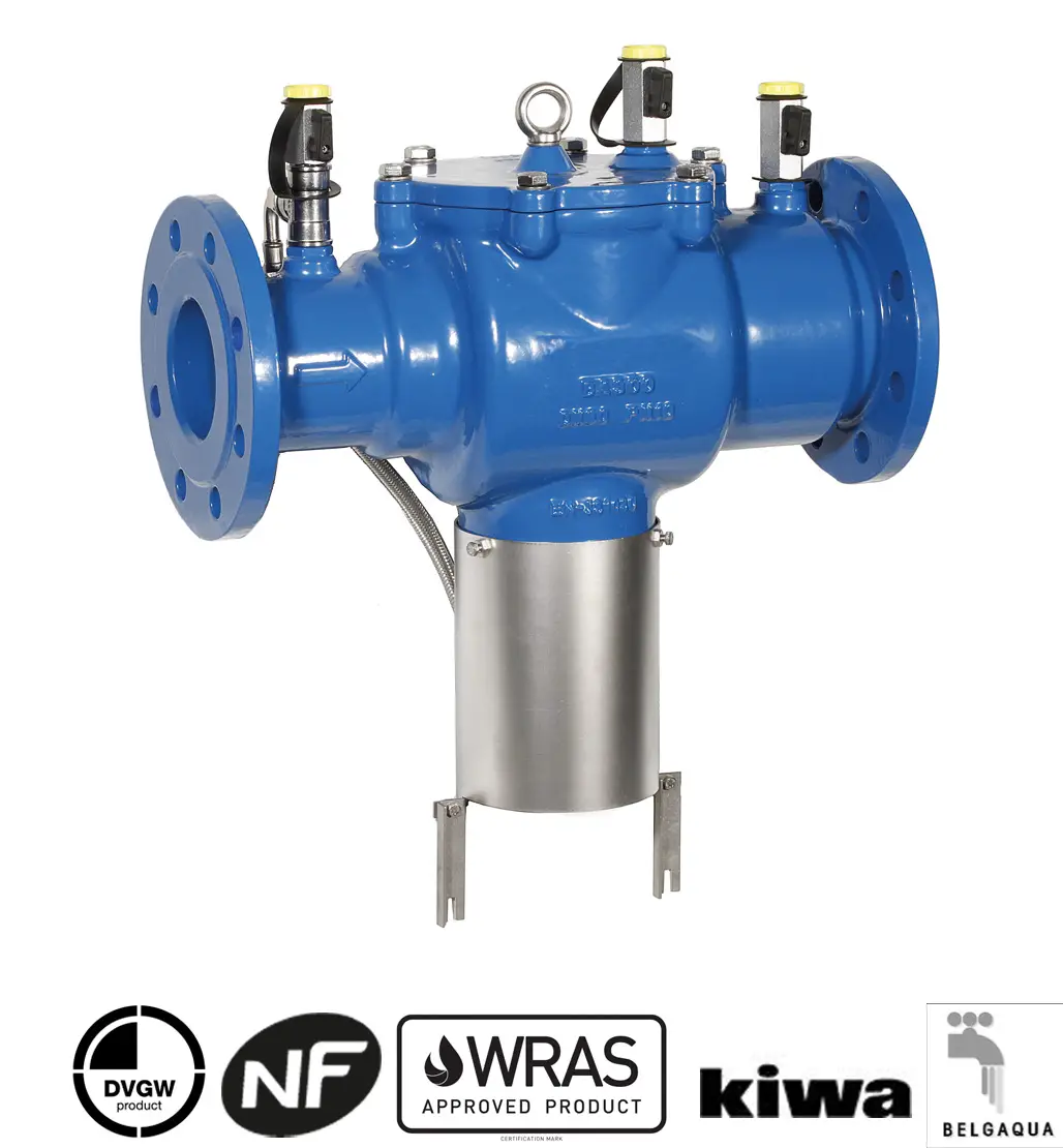
APPROVALS
- DVGW
- BELGIQUE
- NF
- KIWA
- WARS
- SVGW
- VdS (BA300-80ZVDS)
- VA-ETA
SPECIAL FEATURES
- LEAD-FREE: Pb content of all materials less than 0.1 %
- Optimal protection of the drinking water supply system
- Easy access to all internal components
- Powder-coated inside and outside – Powder used is physiologically and toxicologically safe
- Easy Maintenance due to optimized construction
- Triple security – two check valves and a discharge valve separate the backflow preventer into three pressure zones
- Few individual parts
- Lightweight
- Standardized discharge connection
- ACS certified
- All materials are KTW approved
- Approved by OTH (Hungary)
TECHNICAL DATA
| Media | |
| Medium: | Drinking water |
| Connections/Sizes | |
| Connection size: | DN65 – DN200 |
| Discharge pipe connection: | DN150 |
| Pressure values | |
| Min. inlet pressure: | 1.5 bar |
| Max. operating pressure: | 10 bar |
| Operating temperatures | |
| Max. operating temperature medium: | 65 °C (WRAS 60 °C) |
| Specifications | |
| Installation position: | Horizontal with discharge valve downwards |
Product Specification Sheet • EN0H-1242GE23 R0421 • Subject to change
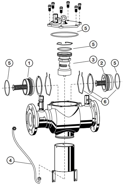
CONSTRUCTION
| Overview | Components | Materials |
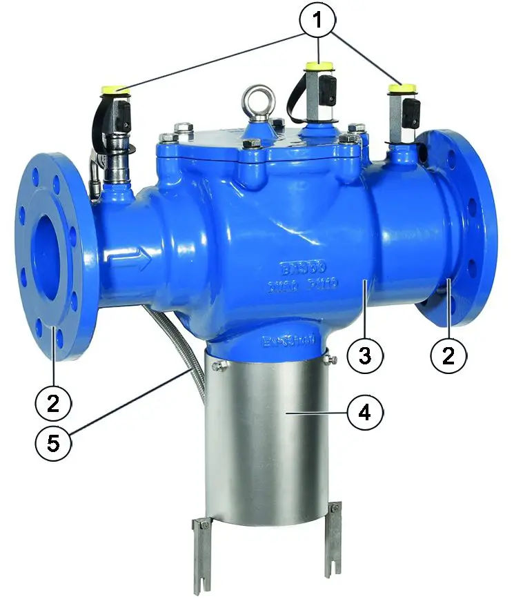 | 1 Three ball valves for the connection of a differential pressure gauge | Brass |
| 2 Inlet/Outlet check valves | Stainless Steel | |
| 3 Housing | Ductile iron, powder-coated with polyamide | |
| 4 Discharge valve | CW626N with stainless steel seat | |
| 5 Pressure control line | Polyethylene with stainless steel braid (BA300-80ZVDS stainless steel) | |
| Not depicted components: | ||
| Diaphragm | EPDM | |
| Sealing washers | EPDM | |
METHOD OF OPERATION
BA-type backflow preventers are divided into three pressure zones. The pressure in zone1 is higher than in zone 2, which in turn is higher than in zone 3. A discharge valve is connected to zone 4 which opens at the latest when the differential pressure between zones 5 and 6 drops to 0.14 bar. The water from zone 7 discharges to the atmosphere, both check valves close and therefore separate zone 8 from zone 9 and 10. In this way, the danger of backpressure or back-siphonage into the supply network is prevented. The pipework connection is interrupted and the drinking water network is protected.
TRANSPORTATION AND STORAGE
Keep parts in their original packaging and unpack them shortly before use.
The following parameters apply during transportation and storage:
| Parameter | Value |
| Environment: | clean, dry, and dust-free |
| Min. ambient temperature: | 5 °C |
| Max. ambient temperature: | 55 °C |
| Min. ambient relative humidity: | 25 % * |
| Max. ambient relative humidity: | 85 % * |
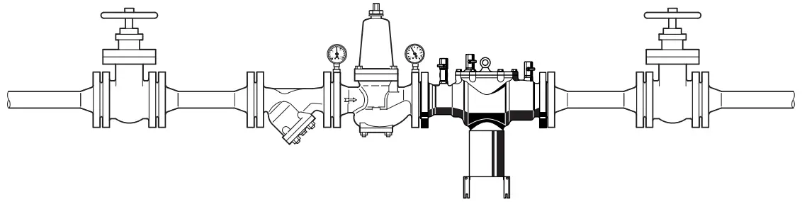
INSTALLATION GUIDELINES
Setup requirements
- Install shut-off valves before and after the backflow preventer
- Install backflow preventer downstream of the filter or strainer
– This protects the appliance against dirt - Install in horizontal pipework with the discharge valve downwards
- Ensure good access
– Simplifies maintenance and inspection - In order to avoid flooding, it is recommended to arrange a permanent professionally dimensioned wastewater connection
- The installation environment should be protected against frost and ventilated well
- Install discharge pipework that has adequate capacity
- These armatures need to be maintained regularly
Installation Example
| Connection sizes: | |||||
| DN: | 65 | 80 | 100 | 150 | 200 |
| inch: | 1 2 /2″ | 3″ | 4″ | 6″ | 8″ |
| Min. clearance above backflow preventer: | 650 mm | 650 mm | 650 mm | 650 mm | 650 mm |
| Clearance from wall: | 160 mm | 160 mm | 160 mm | 200 mm | 200 mm |
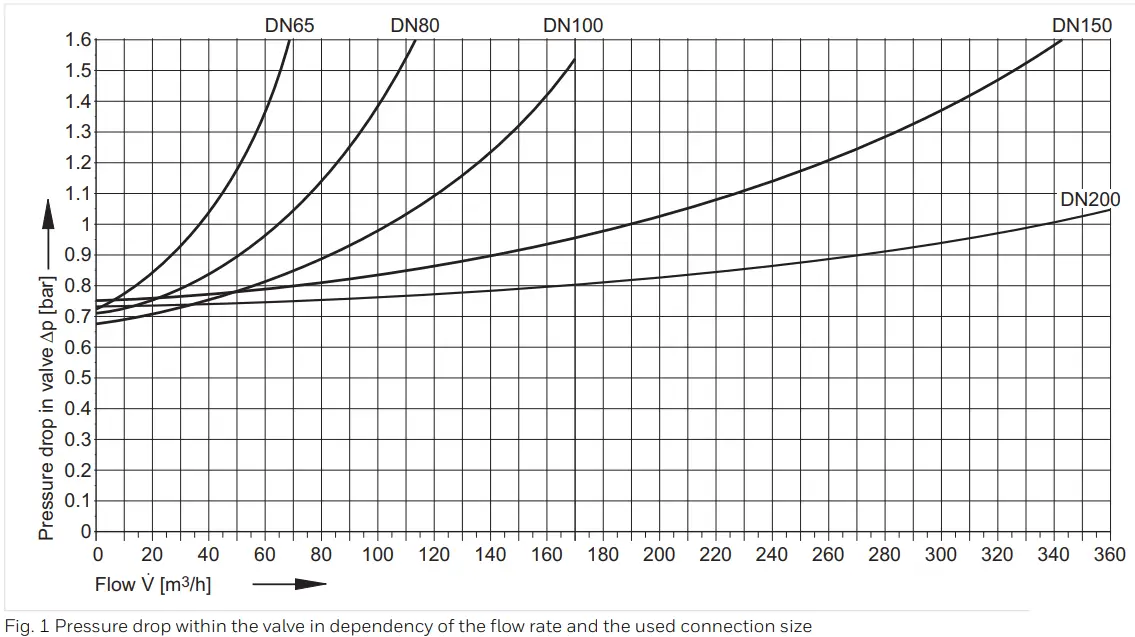
TECHNICAL CHARACTERISTICS
Pressure drop characteristics
DIMENSIONS
Overview
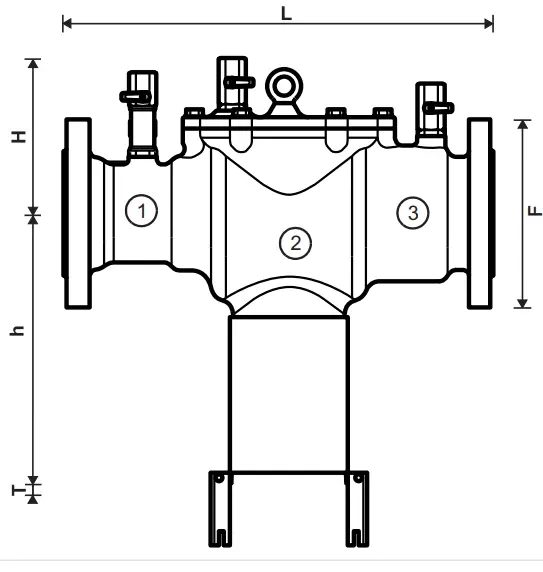
| Parameter | Values | |||||
| Connection sizes: | DN | 65 | 80 | 100 | 150 | 200 |
| Weight: | kg | 23.9 | 32.7 | 44.6 | 70.9 | 114.1 |
| Dimensions: | L | 356 | 440 | 530 | 630 | 763 |
| H | 157 | 172 | 190 | 224 | 259 | |
| h | 246 | 275 | 296 | 314 | 346 | |
| T | 77 | 77 | 77 | 77 | 77 | |
| F* | 185 | 200 | 220 | 285 | 340 | |
| Nominal flow rate at Δp = 1.0 bar: | m3/h | 35.8 | 54.3 | 108 | 190.9 | 339.3 |
| Discharge flow rates in the event of failure: | m3/h | 35 | 35 | 35 | 35 | 35 |
Note:1 to 3 see chapter Method of operation
Note All dimensions in mm unless stated otherwise.
Note:* F = width
ORDERING INFORMATION
The following tables contain all the information you need to make an order of an item of your choice.
When ordering, please always state the type, the ordering or the part number.
Options
These backflow preventers are available in the following sizes: DN65, DN80, DN100, DN150, DN200.
- standard
– not available
| BA300-…A | BA300-80ZVDS | ||
| Connection type: | Standard version, connection sizes DN65 – DN200 Connection with flanges, PN10 | • | |
| with VdS certificate VdS No.: G417057 DN80 | • | ||
Note: … = space holder for connection size
| Description | Dimension | Part No. | ||
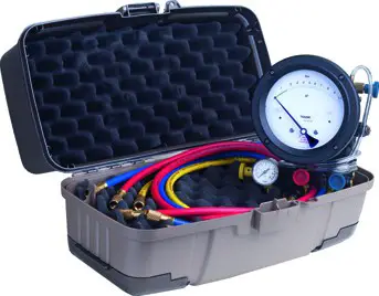 | TKA295 | Test kit Analog pressure measuring device with differential pressure display. With case and accessories, ideal for inspection and maintenance of backflow preventer type BA | ||
| TKA295 | ||||
Spare Parts
Backflow Preventer BA300, from 2011 onwards
| Overview | Description | Dimension | Part No. |
 | 1. Inlet check valve | ||
| DN65 | 904052 | ||
| DN80 | 904053 | ||
| DN100 | 904054 | ||
| DN150 | 904055 | ||
| 2. Outlet check valve | |||
| DN65 | 904057 | ||
| DN80 | 904058 | ||
| DN100 | 904059 | ||
| DN150 | 904060 | ||
| DN200 | 904061 | ||
| 3. Discharge valve | |||
| DN65 – | 904062 | ||
| DN200 | |||
| 4. Pressure control line | |||
| DN65 | 904063 | ||
| DN80 | 904064 | ||
| DN80* | 904073 | ||
| DN100 | 904065 | ||
| DN150 | 904066 | ||
| DN200 | 904067 | ||
| 5. Sealing set | |||
| DN65 | 904068 | ||
| DN80 | 904069 | ||
| DN100 | 904070 | ||
| DN150 | 904071 | ||
| DN200 | 904072 | ||
| 6. Retaining Clip and Ring | |||
| DN65 | 904192 | ||
| DN80 | 904193 | ||
| DN100 | 904194 | ||
| DN150 | 904195 | ||
| DN200 | 904196 | ||
![]() Manufactured for
Manufactured for
and on behalf of
Pittway Sàrl, Z.A., La Pièce 4,
1180 Rolle, Switzerland
For more information
homecomfort.resideo.com/europe
Ademco 1 GmbH, Hardhofweg 40,
74821 MOSBACH, GERMANY
Phone: +49 6261 810
Fax: +49 6261 81309
Subject to change. EN0H-1242GE23 R0421
© 2021 Resideo Technologies, Inc. All rights reserved.


