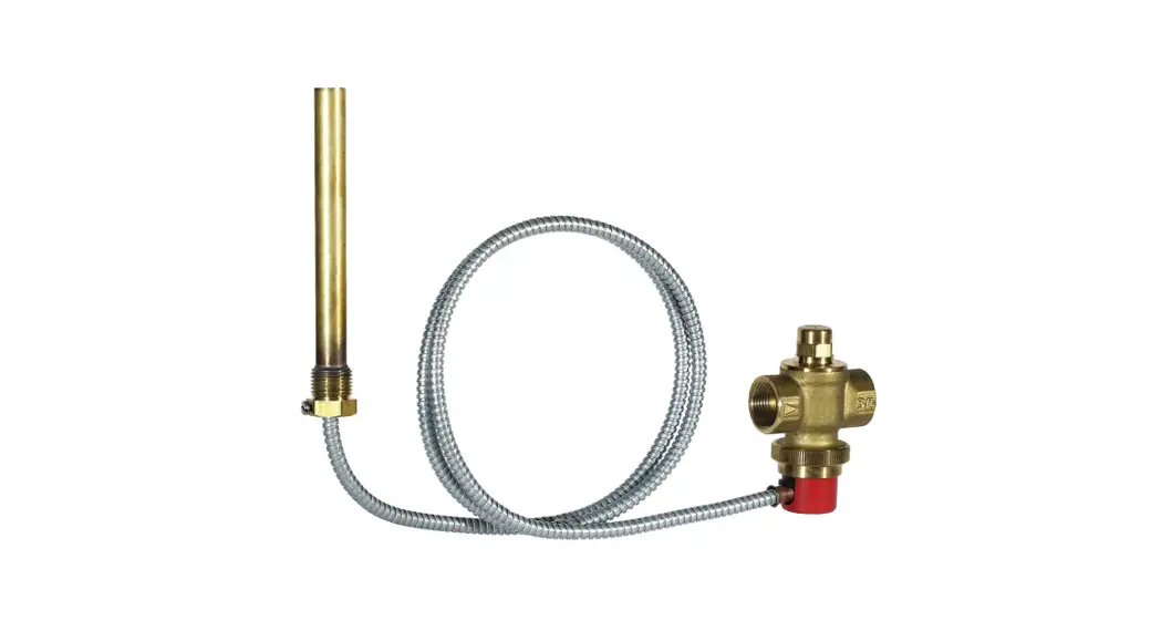
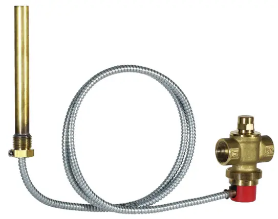
![]() TS131 Braukmann
TS131 Braukmann
Installation instructions
![]() Strandvejen 42
Strandvejen 42
Saksild
8300 Odder 86 62 63 64
www.automatikcentret.dk
[email protected]
Safety Guidelines
- Follow the installation instructions.
- Use the appliance
• according to its intended use
• in good condition
• with due regard to safety and risk of danger. - Note that the appliance is exclusively for use in the applications detailed in these installation instructions (see 2 Technical Data). Any other use will not be considered to comply with requirements and would invalidate the warranty.
- Please take note that any assembly, commissioning, servicing and adjustment work may only be carried out by authorized persons.
- Immediately rectify any malfunctions which may influence safety.
Technical Data
| Media | |
| Medium: | Drinking water |
| Connections/Sizes | |
| Connection sizes: | Rp 3/4″ (DIN EN 10226) |
| Pressure values | |
| Max. operating pressure: | 10 bar |
| Operating temperatures | |
| Operating temperatures: TS131-3/4 A+B TS131-3/4ZAx | 95 °C x =50 / 100 / 110 °C |
| Max. ambient temperature: | 70 °C |
| Specifications | |
| Heating system capacity: | max. 100 kW |
| Capacity: | 2800 kg/h water at the pressure drop D p=1 bar (Inlet pressure 5 bar; Outlet pressure 4 bar; 110°C medium temperature) (1 capillary tube) |
| Mode of operation: | 2 Kp Solid/dual-fuel boilers with integrated water heater or cooling coil in closed heating systems according to EN 12828 |
Options
For Options visit homecomfort.resideo.com/europe
Assembly
4.1 Installation Guidelines
• The valve and the sensor must be installed carefully to avoid any damage to the capillary tube
• The opening on the blow-out line must be clear and easy to monitor
• Ensure no persons are in danger when blowing off the valve
• A sufficiently dimensioned discharge line must be provided
kVS value: ![]() p = 1 bar
p = 1 bar
3 m3/h: with 2 intact sensor systems (with a media temperature of 110 °C)
2.1 m3/h: with one sensor system (with a media temperature of 110 °C)![]() CAUTION!
CAUTION!
Installation of the thermal discharge safety valve does not replace the diaphragm relief value in the cold water supply line to the water heater.
4.2 Assembly instructions
- Install a thermal discharge safety valve according to the installation diagram
• Flow direction is indicated by an arrow - Push the heat sensor into the immersion pipe up to the stop point and secure with a round screw to stop it being pulled out
Start-up
![]() CAUTION!
CAUTION!
On commissioning the heating system, the person preparing the system must check that the thermal discharge safety valve is functioning perfectly.
Maintenance
![]() In order to comply with EN 806-5, water fixtures must be inspected and serviced on an annual basis.
In order to comply with EN 806-5, water fixtures must be inspected and serviced on an annual basis.
As all maintenance work must be carried out by an installation company, it is recommended that a servicing contract should be taken out.
In accordance with EN 806-5, the following measures must be taken:
6.1 Inspection and Maintenance![]() Do not use any cleansers that contain solvents and/or alcohol for cleaning the plastic parts, because this can cause damage to the plastic components – water damage could result.
Do not use any cleansers that contain solvents and/or alcohol for cleaning the plastic parts, because this can cause damage to the plastic components – water damage could result.
Detergents must not be allowed to enter the environment or the sewerage system!
- According to the requirements of EN 12828, the system operator is obliged to have the thermal discharge safety valve checked by a professional at least once a year to ensure its functional readiness.
- Check whether water is escaping from the housing
• if water is escaping, the seals (entire piston guide) must be replaced, or it may be necessary to replace the unit - Operate the check valve and first check whether water is escaping and the valve then closes again
• if no water is escaping or the valve does not close, the unit may have to be replaced
Disposal
Observe the local requirements regarding correct waste recycling/disposal!
Spare Parts
For Spare Parts visit homecomfort.resideo.com/europe
![]() Manufactured for and on behalf of
Manufactured for and on behalf of
Pittway Sàrl, Z.A., La Pièce 4,
1180 Rolle, Switzerland
by its authorised representative
Ademco 1 GmbH
For more information
homecomfort.resideo.com/europe
Ademco 1 GmbH, Hardhofweg 40,
74821 MOSBACH, GERMANY
Phone: +49 6261 810
Fax: +49 6261 81309
© 2020 Resideo Technologies, Inc. All rights reserved.
Subject to change. MU1H-1543GE23 R0420


