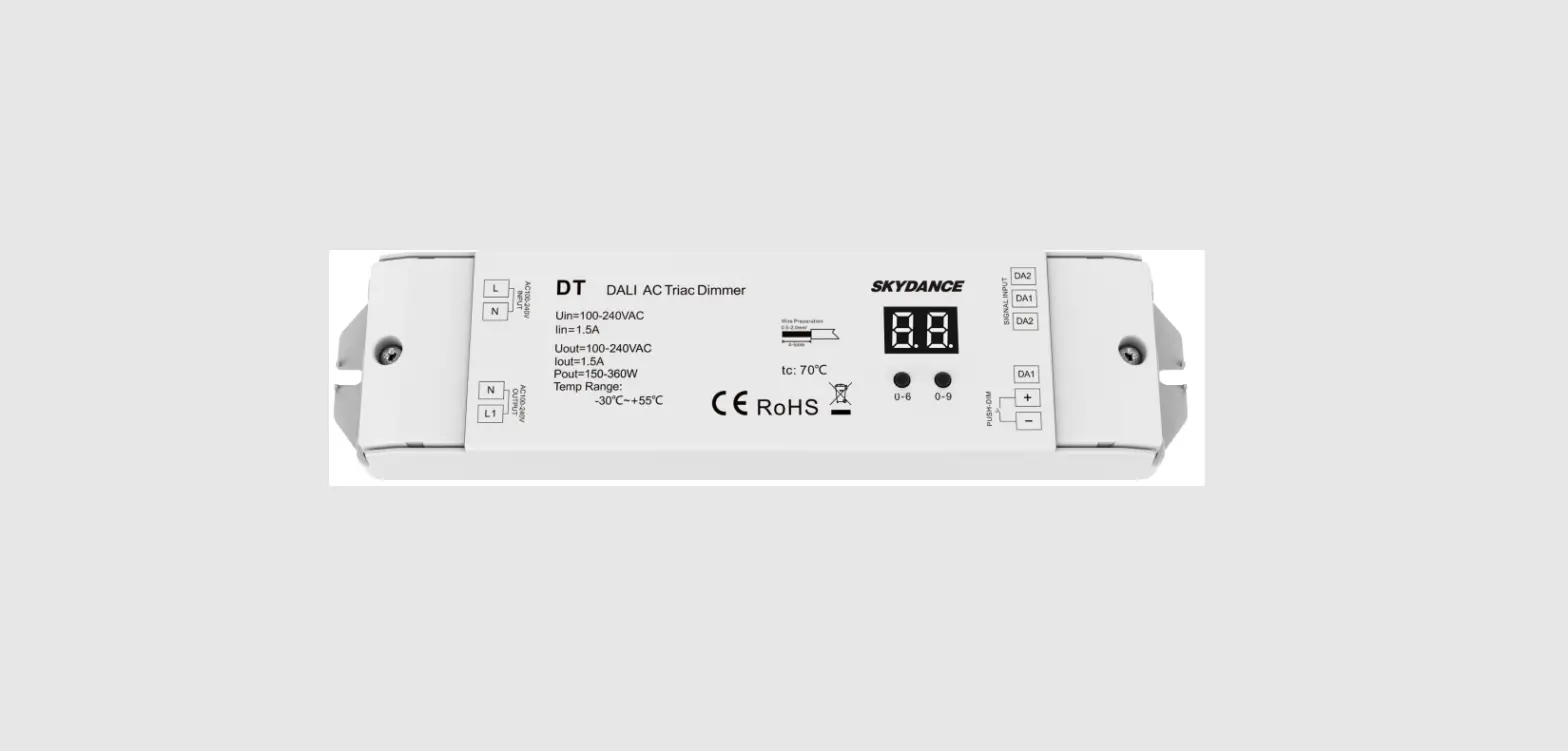
SKYDANCE DT AC Triac DALI Dimmer
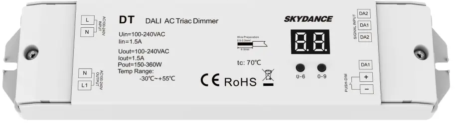
AC Triac DALI Dimmer
Model No.: DT
1DALI address/1 Channel output/Leading edge or trailing edge/Numeric display
Features
- AC phase-cut Mosfet DALI dimmer, one DALI address, and one channel output.
- In accordance with DALI standard protocol IEC 62386-102, IEC 62386-207 and in compliance with DALI products from other international incorporation.
- DALI address can be manually assigned and shown in digital display or automatically assigned by DALI master.
- Reverse-phase dimming or forward-phase dimming selectable.
- Connect with external push switch to achieve on/off and 0-100% dimming function.
- To dim and switch single color dimmable LED lamps, traditional incandescent and halogen lights.
- Over-heat protection, recover automatically.
Technical Parameters
| Input and Output | |
| Input voltage | AC100-240V |
| Output voltage | AC100-240V |
| Output current | Max 1.5A |
| Output power | 150-360W |
| Safety and EMC | |
| EMC standard (EMC) | ETSI EN 301 489-1 V2.2.3 ETSI EN 301 489-17 V3.2.4 |
| Safety standard(LVD) | EN 62368-1:2020+A11:2020 |
| Certification | CE,EMC,LVD |
| Environment | |
| Operation temperature | Ta: -30 OC ~ +55 OC |
| Case temperature (Max.) | T c: +70OC |
| IP rating | IP20 |
Compatible Load Types
| Load Type | Maximum Load | Remarks |
| Dimmable LED lamps | 200W @ 220V 100W @ 110V | Due to variety of LED lamp designs, maximum number of LED lamps is further dependent on power factor result when connected to dimmer. |
| Triac Dimmable LED drivers | 200W @ 220V 100W @ 110V | Maximum permitted number of drivers is 200W divided by driver nameplate power rating, and make sure the surge current is no more than 2 times 65A. |
| Incandescent lighting, HV Halogen lamps | 400W @ 220V 200W @ 110V |
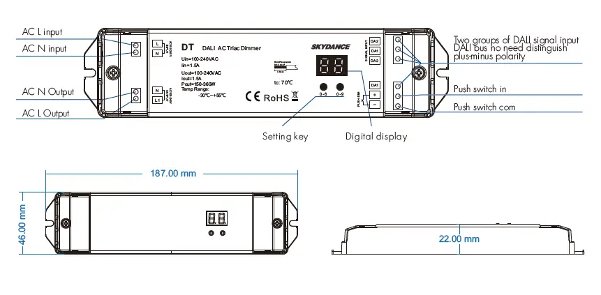
Mechanical Structures and Installations
Wiring Diagram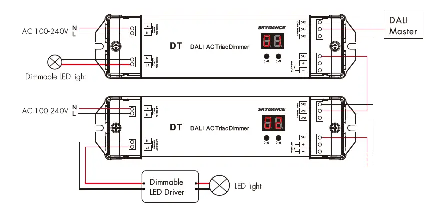
Caution:
Please carefully ensure all wire connections and polarities are correct and secure before applying power, otherwise this controller will be damaged.
Note: When calculating the maximum number of load lamps or drivers, the input power or input current parameters of a single lamp or driver must be used, the output power parameters can not be used. In addition, the maximum surge current of the dimmer is 65A, the sum of surge current of multiple dimmable LED drivers should not exceed 2 times. otherwise, the product will be overloaded and damaged.
Operation
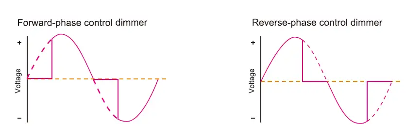
Reverse-phase or forward-phase dimming setting
Long press two buttons at the same time for 2s, and switch between reverse-phase dimming(“CR”) or forward-phase(“CF”) dimming.
Minimum brightness setting
- Under Reverse-phase or forward-phase dimming setting, Long press two buttons at the same time for 2s, digital display starts flashes.
- Short press first button to set the “tens” position and the second button to set the “units” position.
- The minimum brightness can be set to 1%~40%, the factory default is 10%.
- Long press any of the two buttons for 2s or timeout 10s, quit Minimum brightness setting, and digital display stop flashes.
Set DALI Address via buttons
- Long press any of the two buttons for 2s, prepare to set the start DALI address, and digital display start flashes.
- Short press first button to set the “tens” position and the second button to set the “units” position.
- The address can be set from 00~63-FF. no DALI address is assigned for the dimmer, the digital display shows “FF”.
- Long press any of the two buttons for 2s or timeout 10s, quit start DALI address setting, digital display stop flashes.
DALI address assigned by DALI masters
DALI address can also be assigned by DALI Master controller automatically. Please refer to user manuals of compatible DALI Masters for specific operations. The digital display will show “AU” When the DALI master is assigning address. After address is assigned, the digital display will show the start DALI address”xx”, xx is from 00 to 63.
Push-Dim Function
The provided Push-Dim interface allows for a simple dimming method using commercially available non-latching(momentary) wall switches.
- Short press:
Turn on or off the light. - Long press (1-6s):
Press and hold to step-less dimming, With every other long press, the light level goes to the opposite direction. - Dimming memory:
Light returns to the previous dimming level when switched off and on again, even at power failure. Synchronization: If more than one controller is connected to the same push switch, do a long press for more than 10s, then the system is synchronized and all lights in the group dim up to 100%. This means there is no need for any additional synchrony wire in larger installations. We recommend the number of controllers connected to a push switch does not exceed 25 pieces, The maximum length of the wires from push to the controller should be no more than 20 meters.
Safety & Warnings
- DO NOT install with power applied to device.
- DO NOT expose the device to moisture.


