![]()
![]()
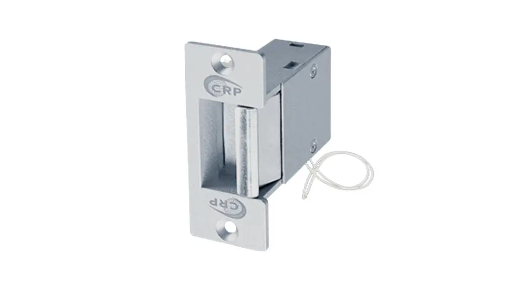
ES1433 Series
Electric Strike Installation Instructions
The ES1433 Series electric strikes are designed to accommodate cylindrical locksets with up to3/4″ (19mm) latch throw. The strikes can be configured to fail-safe or fail-secure on site.
Specifications
| Operating Voltage | 12 / 24VDC |
| Current Draw | 300mA / 12VDC, 150mA / 24VDC |
| Operating Temperature | 32°F to 120°F (0°C to 49°C) |
| Humidity | 0% to 85% Non-condensing |
| Latch Throw | 3/4″(19mm) [ 5/8″(16mm) strike depth, 1/8″(3mm) door gap ] |
| Keeper Width | 1 7/16″ (36mm) |
| Static Strength | 1500 lbs (680Kg) (UL Witness test: 2000lbs) |
| Dynamic Strength | 70 ft-lbs |
| Endurance | 250,000 cycles (UL tested) 1,000,000 cycles (Factory tested) |
| Performance Level | Destructive Attack: Level I Line Security: Level I Standby Power: Level I Endurance: Level IV |
Fail-Safe/ Fail-Secure Reversible
Change screw position at fail-safe/fail-secure hole to the desired setting.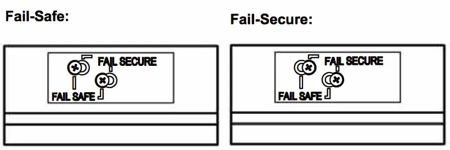
Frame Application


| Model | Latch Monitor | Body Construction |
| ES1433 | – | Zinc Alloy |
UL Requirements
- For indoor use only.
- Wiring methods shall be in accordance with NFPA70.
- The ES1433 series is intended to be used with UL Listed Exit Hardware.
- The ES1433 series shall not impair the intended operation of an emergency exit.
- The ES1433 series shall not impair the operation of panic hardware mounted on the door.
ES1433 Series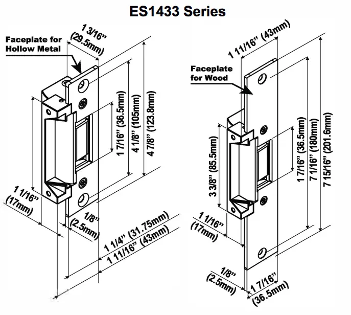
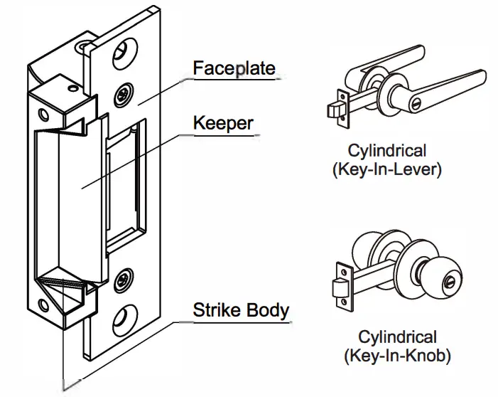
Compatible Locksets
 Installation Instructions
 Installation Instructions
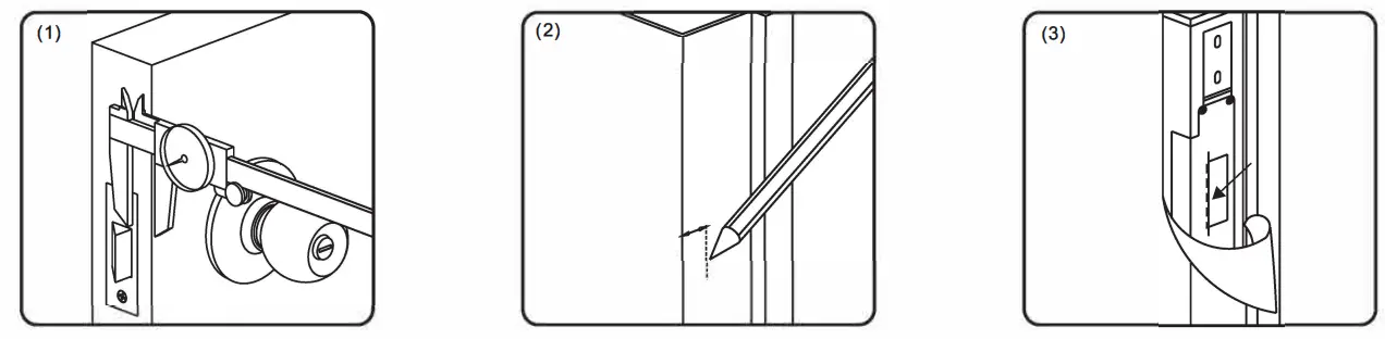 | ||
| Measure latch position. | Mark latch position line. | Attach sticker template to the marked centerline. |
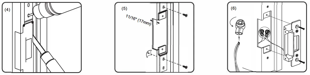 | ||
| Cut hole using template. | Install the mounting tabs. | Connect the wires using the crimp connectors, then test the strike, ensure to give it the correct voltage. |
Caution:
The proper gap must be reserved between the strike keeper and latch bolt to prevent failure of the solenoid valve.
Using the Trim Plate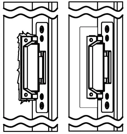 In case of over-cutting, use the enclosed trim plate to cover up any errors.
Installing the Crimp Connectors:
Crimp connectors are provided to make wiring connections easier and more reliable. To install the connectors: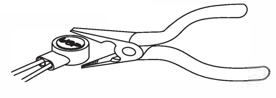
- Insert the wires into the connector.
- Use a crimping tool or pliers to evenly press down on the head of the connector.
12 / 24 VDC Plug-In Wiring
For 12VDC Operation: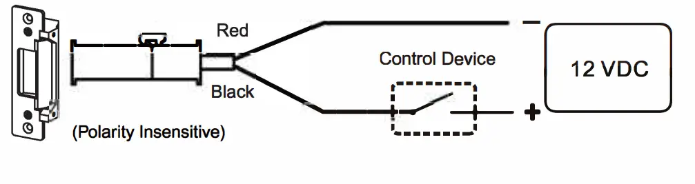 For 24VDC Operation:
![]()
DWG # ELG8009, P/2, 20220407


