
GIANNI INDUSTRIES GK140 Electric Strikes Instruction Manual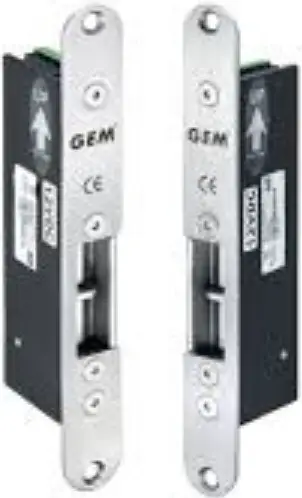
Specifications
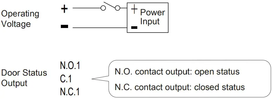
- Operating Voltage: 12 or 24 VDC
- Voltage Tolerance: ±10%
- Current Draw: 700mA/12VDC ; 350mA/24VDC
- Operating Temperature: 14°F to 120°F (-10°C~+49°C)
- Humidity: 0~85% non-condensing
- Solenoid Testing: Over 250,000 cycles
- Preload: Up to 200 lbs
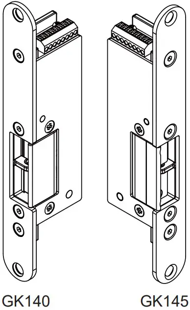
- Static Strength: 1,200 lbs (GK140 Series) 1,000 lbs (GK145 Series)
- Construction: Stainless steel
- Net Weight: 673g
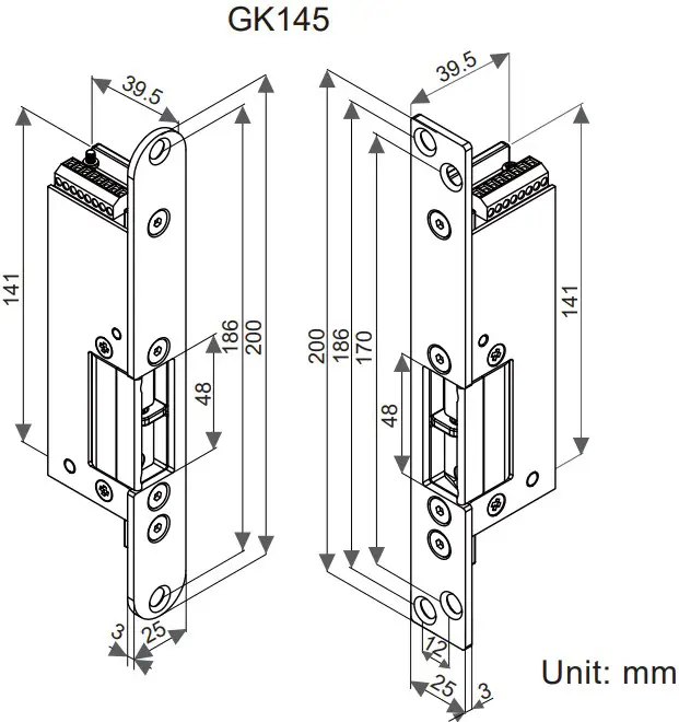
- Latch Throw: GK140: 15 mm, GK145: 11 mm (With 3mm door gap)
- Keeper Width: 48mm
- Lock Mode: Fail-secure
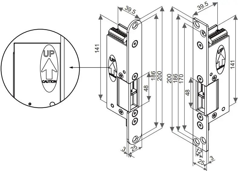
Attention!
Please follow the sticker’s instruction to install the strike.
Keeper Adjustment (GK145 Only)
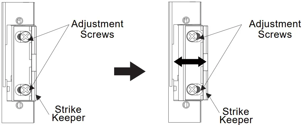
The strike keeper can be adjusted horizontally to account for various installation anomalies. To adjust the keeper, loosen the adjustment screws, move the keeper horizontally as needed, and retighten the adjustment screws. (Maximum adjustable range: 3mm)
Handing Guide
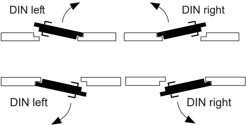
Door handing is determined from the side of the door where the hinges are visible, according to the German standard DIN 107. Stand facing the door on the hinge / pull side. If the hinge is on the right, the door is considered to be DIN right. If the hinge is on the left, then the door is considered to be DIN left.
Models (M: Door Status Monitor)
| DIN left | DIN right | ||
| GK140-L-12 | GK145-L-12 | GK140-R-12 | GK145-R-12 |
| GK140M-L-12 | GK145M-L-12 | GK140M-R-12 | GK145M-R-12 |
| GK140-L-24 | GK145-L-24 | GK140-R-24 | GK145-R-24 |
| GK140M-L-24 | GK145M-L-24 | GK140M-R-24 | GK145M-R-24 |
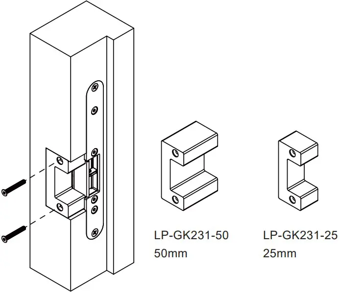
Optional Brackets
Lip extension brackets are available for wider jambs.
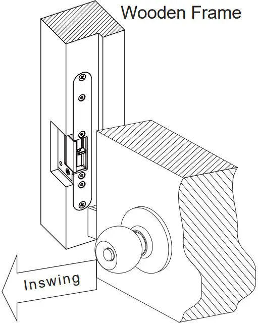
Mortise Mount in Wooden Frame
Wiring Diagram
Installation Steps
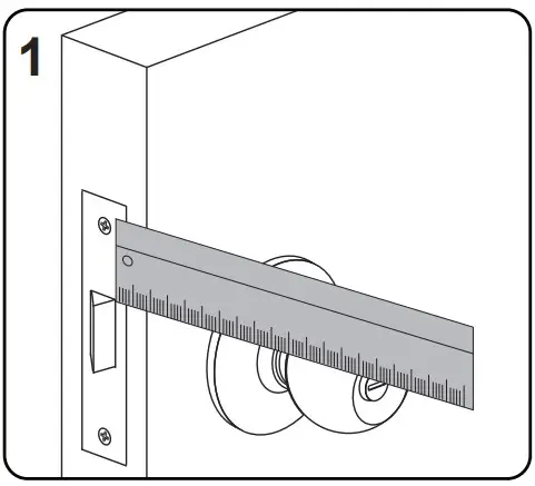
- Measure the vertical and horizontal position of the latch bolt on the door leaf.

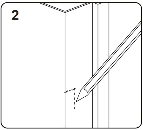
- Mark the position of the latch bolt on the door frame as shown in the figure.
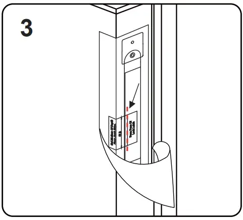
- Mount the supplied template and align to the marked line.
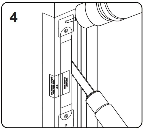
- Drill and cut the frame according to the template.
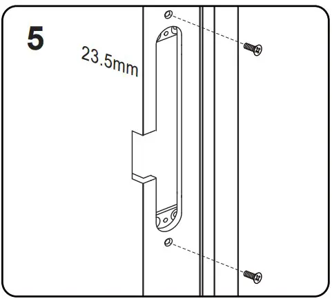
- Tighten the indicated screws.
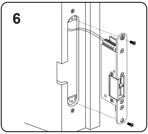
- Connect the wires and install the strike.
![]() Note
Note
It must be ensured that there is a small space between the latch bolt and actuated latch stop when the door is closed and the latch bolt is in its locked position. This will relive pressure on the solenoid valve and reduce the risk of failure when opening the door.


