CAL-ROYAL ES1934 Electric Rim Strikes
Specifications
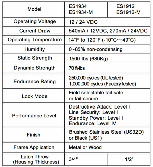
UL Requirements
- For indoor use only
- The ES1934 / ES1912 Series are intended to be used with UL Listed Exit Hardware.
- The ES1934 / ES1912 Series electric strikes are access control unit accessories, intended to be controlled by an access control system. The access control system’s purpose is to provide a means for controlling the locking and unlocking of external and internal doors of a premise.
- The ES1934 Series shall not be installed in the fail secure mode unless permitted by the local authority having jurisdiction and shall not interfere with the operation of panic hardware.
- The Fire Rated ES 1934 Series electric strike is to be used only with UL Listed Rim Type Fire Exit Hardware, Von Duprin LLC, Model 99-F.
- Remove the Listed Fire Rated Hardware label if the ES1934 Series Electric Strike will be used in the fail-safe operation. Using the above-mentioned strike in fails safe operation negates the fire rating.
- The ES1934 Series Electric Strike is Fire Rated in Fail Secure operation only.
Surface Installation
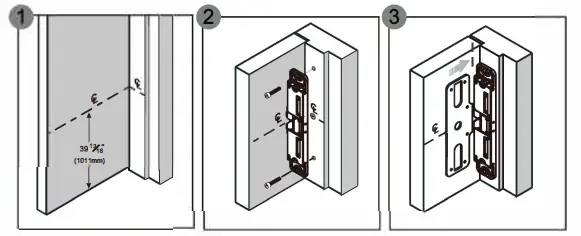
- Measure 39 13/16″ (1011 mm) up from the finished floor and mark strike centerline on door. Transfer centerline to frame.
- Align strike on the centerline and mark two slotted holes. Drill holes and install strike to frame.
- Align template on centerline and against strike.
For Exit Device Already Installed
Model ES1912 is used as example below.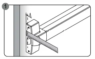
- a. Measure the exit device latch position on the door.

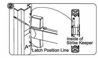
- a. Close the door and mark latch position on the frame.
- b. The latch position line will correspond with the inside of strike keeper as shown.

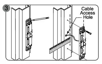
- a. Position the strike on the frame according to the marked latch position.
- b. Use the strike as a template; mark and drill cable access hole and two mounting holes.
- c. Loosely mount the strike with Phillips flat head screws.

- a. Check latchbolt interaction and adjust the strike horizontally until the door latches properly.
- b. Tighten the two mounting screws and mark remaining screw holes.

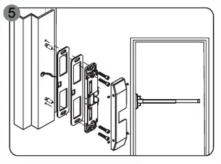
- a. Remove the strike and drill holes.
- b. Connect the wires.
- c. Insert the blind nuts into the holes and re-install the strike.
- d. Add spacers to adjust the gap between strike and exit device if necessary.
- e. Permanently secure the strike with the hex socket cap screws into the blind nuts.
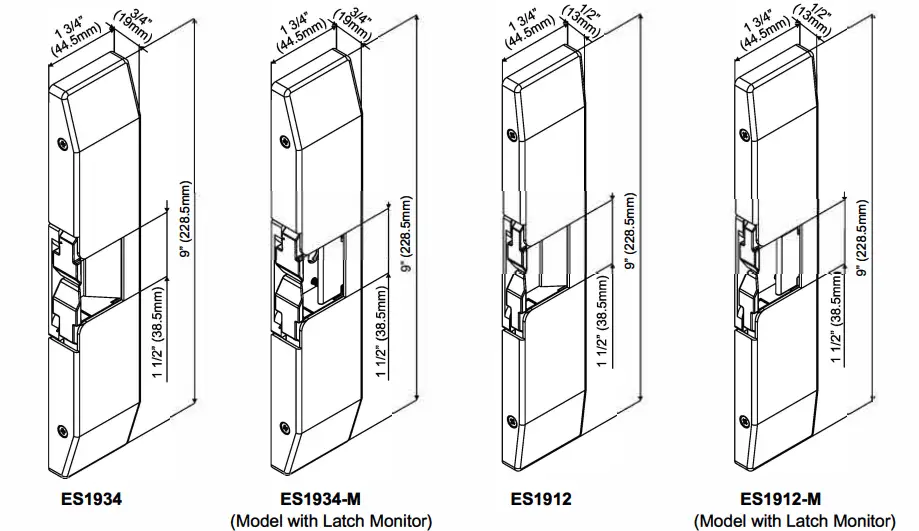
Dimensions
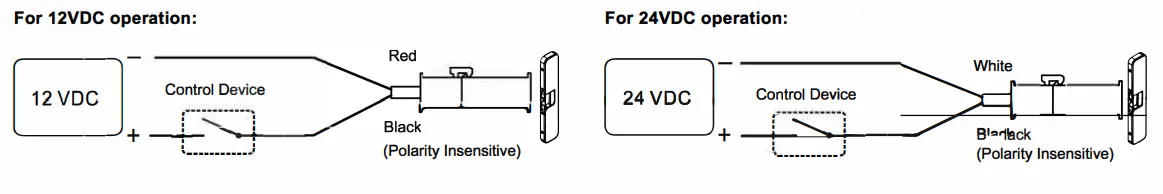
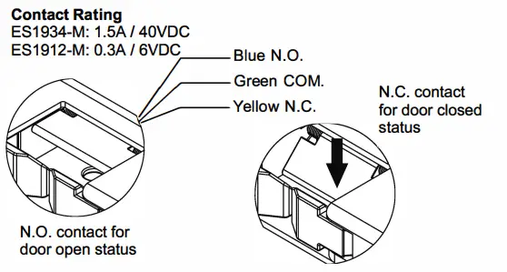
Wiring Diagrams
Latch Monitor (Option)
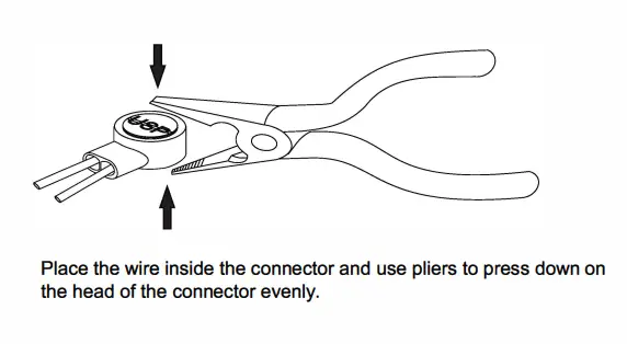
Installing the Crimp Connectors
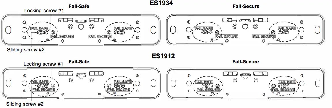
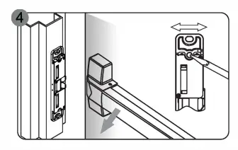
Changing Fail-Safe / Fail-Secure
Remove locking screw #1, loosen, slide and tighten sliding screw #2. Reinsert and tighten locking screw #1 to the desired fail-safe or fail-secure setting.