![]() INSTALLATION INSTRUCTIONS
INSTALLATION INSTRUCTIONS
30-4
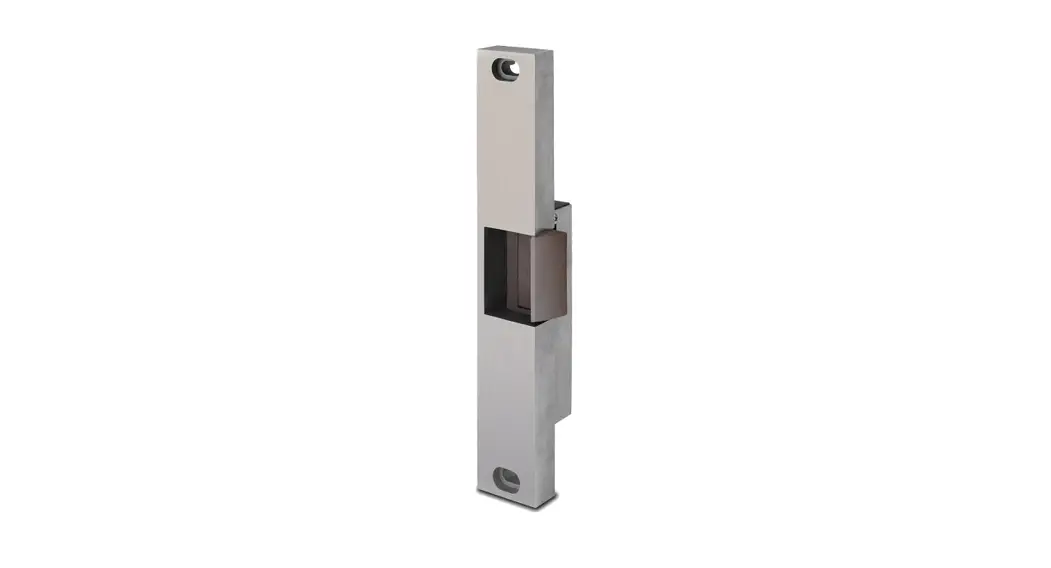
RIM MOUNT ELECTRIC STRIKE
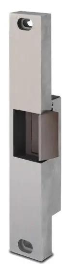
Specifications:
| Voltage: | .51 Amps @ 12 VDC .25 Amps @ 24 VDC |
| Models: | 30 – 4 – 12 30 – 4 – 24 |
| Options: | FS – Fail-Safe LCBMA-30 – Latch & Locking cam monitoring |
Any suggestions or comments on this instruction or product are welcome. Please contact us through our website or email [email protected]
CAUTION!
Before connecting any device at the installation site, verify input voltage using a multimeter. Many power supplies and low voltage transformers operate at higher levels than listed. Any input voltage exceeding 10% of the solenoid rating may cause severe damage to the unit and will void the warranty.
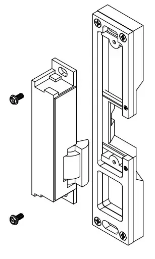
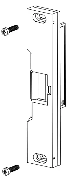
Preparing the Strike
- Attach the faceplate to the strike body using the #12-24 x 3/8″ Body Mounting screws as illustrated on Page 3.
- IF using the LCBMA (Latchbolt & Locking Cam Monitor), See the Image below for wiring instructions.
NOTE: The strike body ships as either a 12 or 24-volt unit and do not field selectable. - VERIFY the available voltage is +/- 10% of the rated voltage of the strike body.
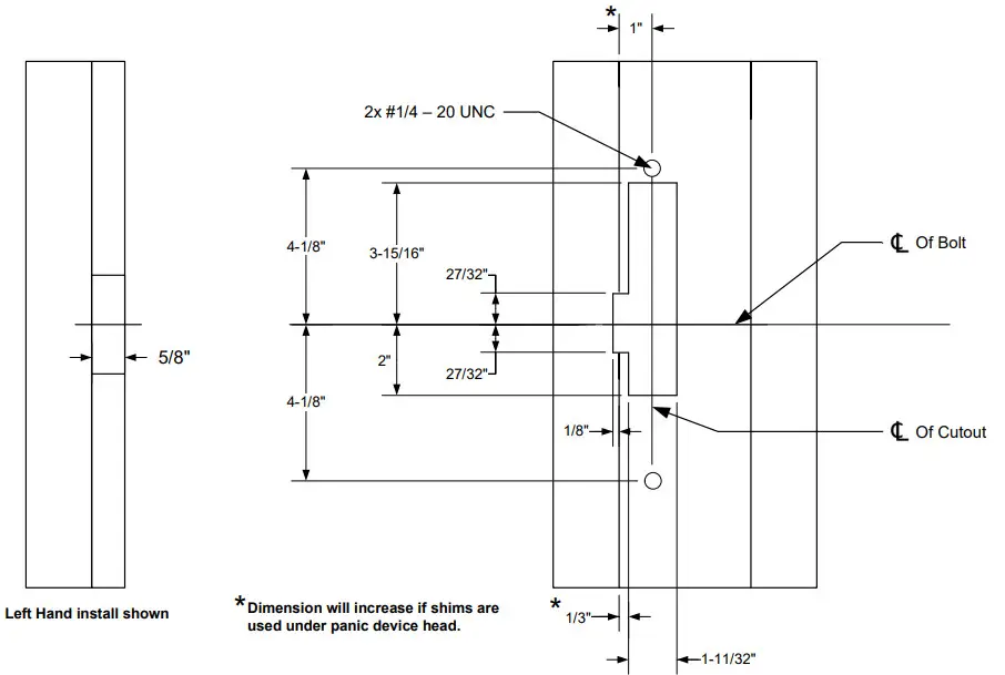
- PREPARE frame using the dimensional reference on Page 4.
- TEST FIT the electric strike in the door frame.
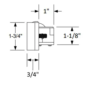
- IF there is not enough clearance between the exit device and the door strike, THEN REMOVE the spacer plate as shown on Page 3.
Finishing the Installation - CONNECT the Plug Connector to the electric strike and CONNECT wires from the Plugin Connector lead to the power source.
- INSTALL the electric strike unit in jamb cutout, using the provided #12-24 x 1/2″ faceplate mounting screws
- ADJUST the strike horizontally as shown on Page 3. to accommodate any door silencers or smoke seal
Monitoring Switches
| Latchbolt Monitor (LBM) | |
| White: | COM |
| Orange: | N/O |
| Green: | N/C |
| Locking Cam Monitor (LCM) | |
| Brown: | COM |
| Blue: | N/O |
| Yellow: | N/C |
| * When secured | |
Attaching the Faceplate
- To attach the 30-4 series electric strike body to the faceplate, INSTALL with two #8-32 body mounting screws as shown.
- ADJUST the keeper position as needed before tightening screws.
- ENSURE body mounting screws are tightened and secured after adjustment is made.
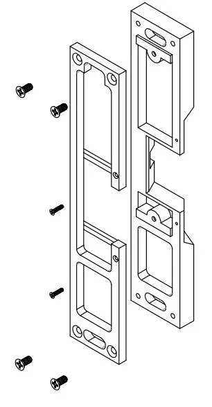
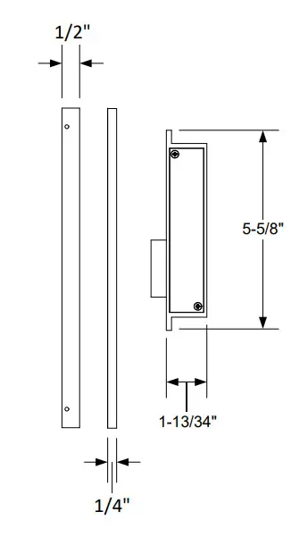
Removing the 1/4″ Spacer Plate
NOTE:
A 1/ 4″ spacer plate is preinstalled on the striking faceplate. Removal of the spacer plate will decrease faceplate thickness from 3/4″ to 1/2″.
- REMOVE the four #8-32 screws and two #2-56 screws.
- REMOVE the spacer plate.
Adjusting the Horizontal
- LOOSEN the two #1/4 – 20 faceplate mounting screws.
- ADJUST the strike to the appropriate position.
- TIGHTEN the two #1 4 – 20 faceplate mounting screws.
NOTE:
A 3/8″ set screw is provided. Proper selection will secure the #1/ 4 – 20 faceplate mounting screws, but not protrude from the strike body. - LOCKDOWN the adjustment by installing the provided set screws.
Strike Dimensions
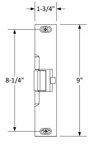 |  |  |
Dimensional Drawing Only Not Drawn to Scale
Frame Dimensional Cutout
SECURITY DOOR CONTROLS ■ WWW.SDCSECURITY.COM
[t] 800.413.8783 ■ 805.494.0622 ■ E-mail: [email protected] ■ 801 Avenida Acaso, Camarillo, CA 93012 ■ PO Box 3670, Camarillo, CA 93011
P:\INST INSTRUCTIONS\ELECTRIC STRIKES\INST-30-4 Rev B 03-21


