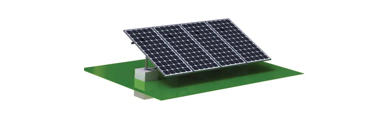
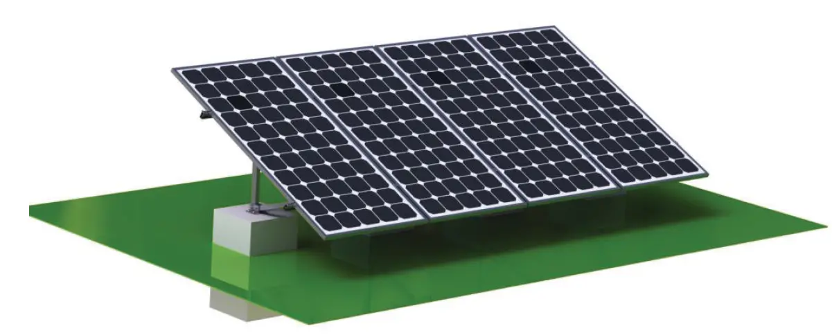
EG4 Brightmount Fixed Angle Ground Mount System
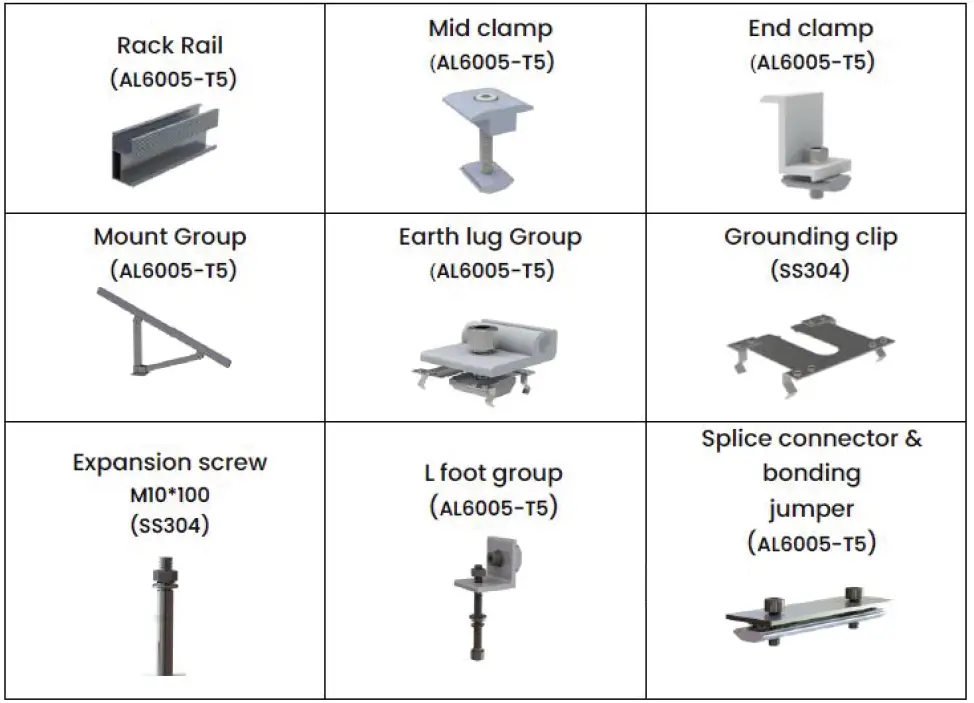
PARTS DIAGRAM
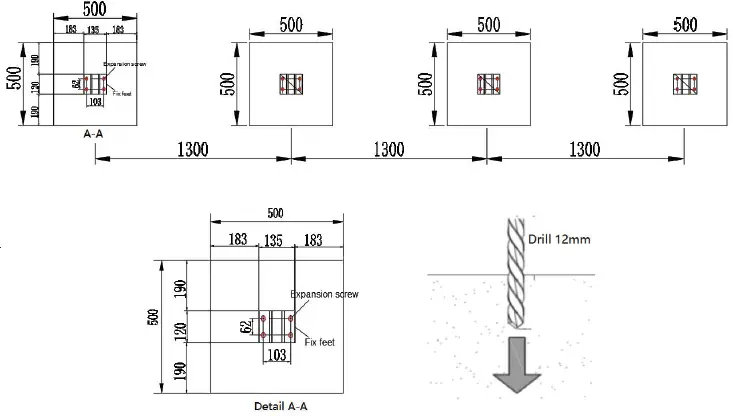
DIMENSIONS AND LAYOUT
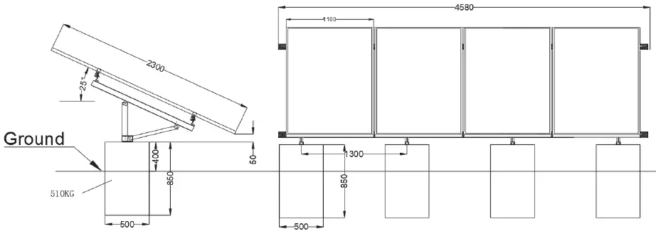 All measurements above are in millimeters.
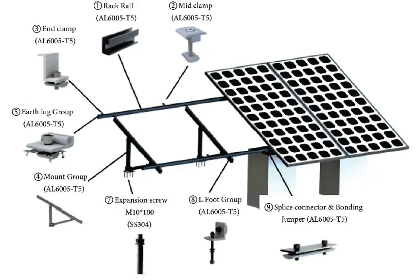
INSTALLATION
Tools Needed
- Glove
- Power Tool
- Crescent Wrench
- Meter Rule
- Drill 12.5 mm
- Allen Wrench

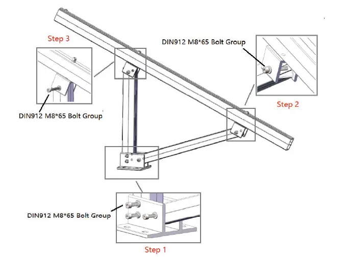
- Install leg group
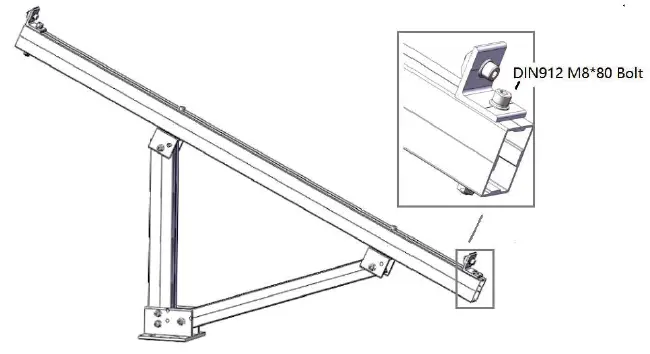
Using a M8’80 bolt, M8 washers, M8 nut install the U45 connector as shown to the right.
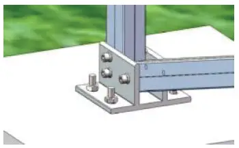
- Install mounting bracket
Using M8’65 bolts, M8 washers and M8 nuts to connect the legs to the mounting bracket as shown to the left.
- Install ‘L’ foot
M8’65 bolt, M8 washers, and M8 nut to install the ‘L’ foot.
- Connect the mounting bracket to concrete anchor.

- Use the expansion screws when mounting.

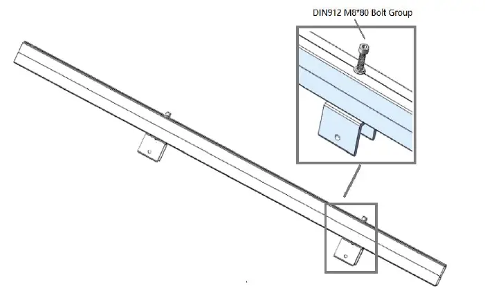
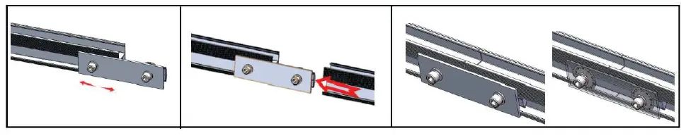
- Follow these images for rail installation.

- Connect the frames together using junction brackets, and M8 allen bolts.

- Completed construction.

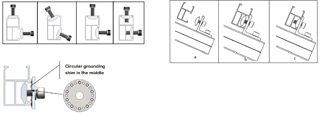

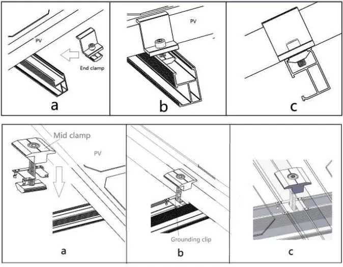
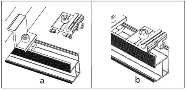
PV ATTACHMENT
- Install PV modules using the End & Mid clamps

- Install earth lug on the end of the rails.

www.eg4electronics.com
[email protected]
Sulphur Springs. TX
October 2022
Rev A Specifications subject to change without notice


