EG4 6000 Adjustable Ground Mount System Installation Guide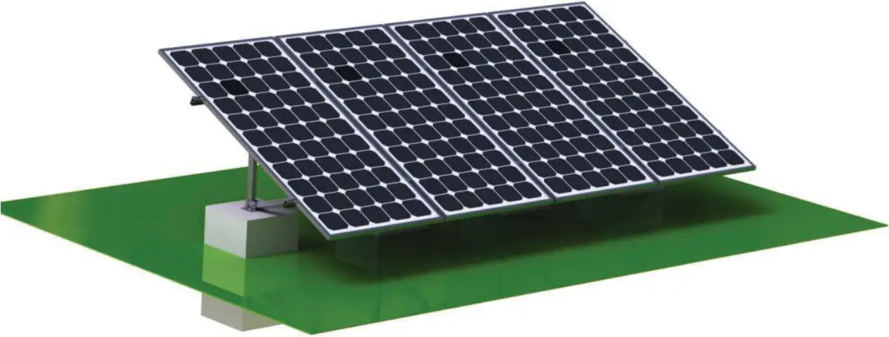
PARTS
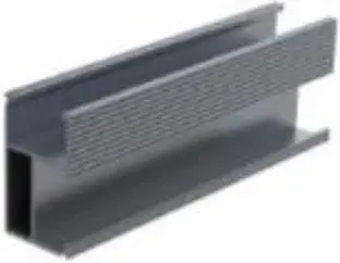
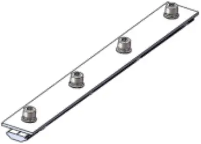
- Rack Rail

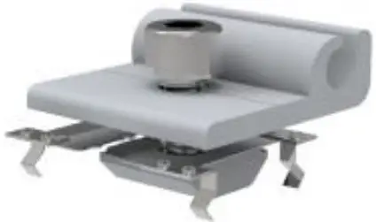
- Mid Clamp

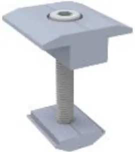
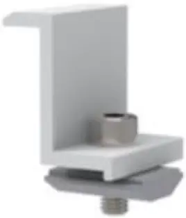
- End Clamp

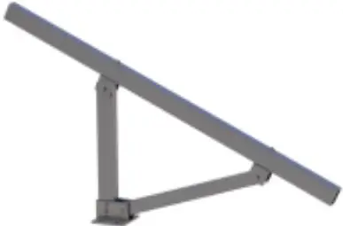
- Mount Group

- Grounding Lug Group

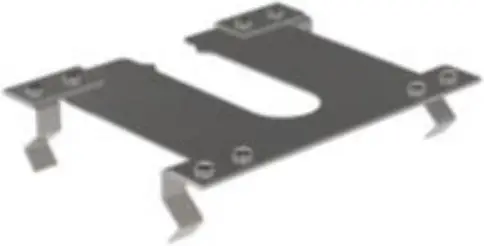
- Grounding Clip

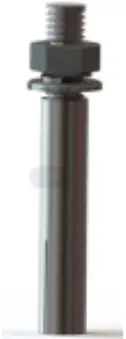
- Anchor Bolt M10*100

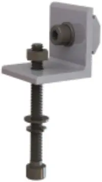
- L Foot Group

- Splice Connector and Bonding Jumper

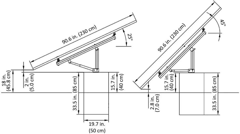
DIMENSIONS AND LAYOUT
ENGINEERING DRAWINGS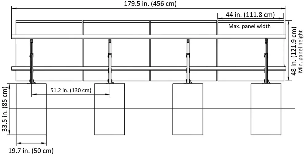
LAYOUT AND INSTALLATION
OVERALL LAYOUT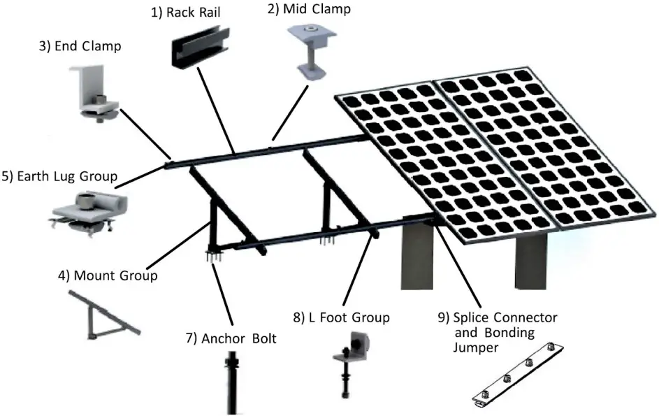
Tools Needed
- Gloves

- Drill

- Adjustable Wrench

- Tape Measure

- Drill Bit 1/2 in

- Allen wrench Set


Torque Recommendations:
| Bolt | Recommended Torque | RecommendedBoltTorque | Bolt | Recommended Torque |
| 1 M8 bolt, M8 nut | 115 in. lbs. (13 Nm) | I M10 bolt, 140 in. lbs.M10 nut | M8 bolt, N2 nut | 97 in. lbs. (11 Nm) |
INSTALLATION
A) Leg Group Assembly
Use M8*80 bolts, M8 spring washers, flat washers, and M8 nuts to install the U connectors as shown in the illustration to the right.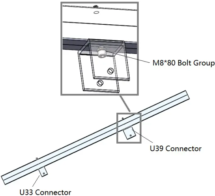
Use M8*65 bolts, M8 spring washers, flat washers, and M8 nuts to install the mount group as shown in the illustration to the left.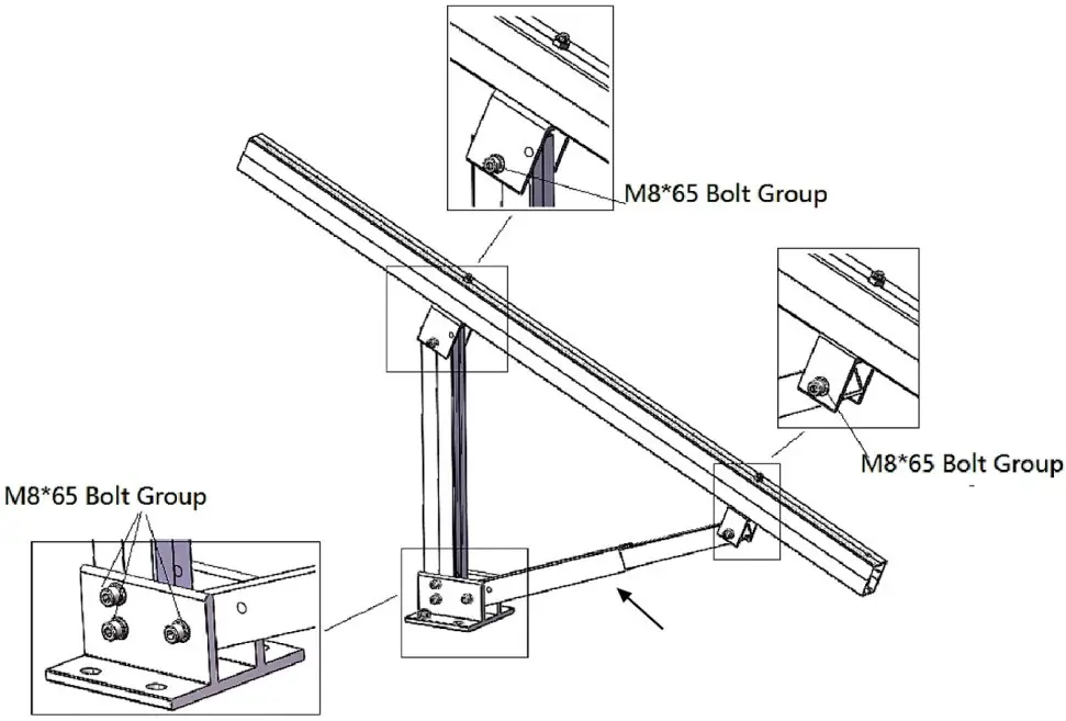
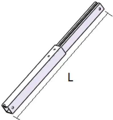
The adjustable leg is used to change the angle of the array. Adjustment instructions are on the following page.
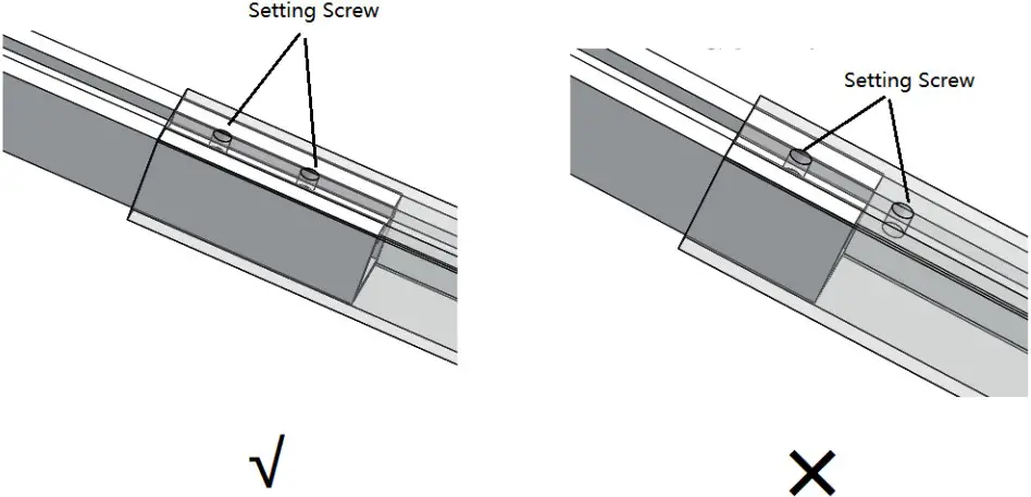
Loosen set screws to adjust the angle of the array. Different angles correspond to the lengths provided in the chart below. The recommended torque for the set screws is 80 in. lbs. (9 Nm). Note: Both set screws must be secured to lock the adjustable leg in place.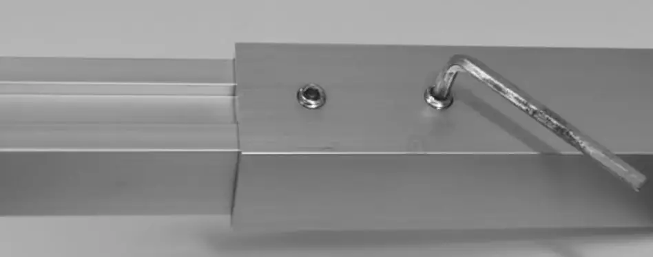
Use M8*80 bolts, M8 spring washers, flat washers, and M8 nuts to install L feet as shown in the illustrations to the right.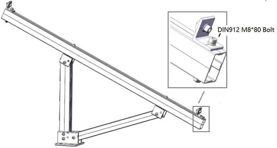
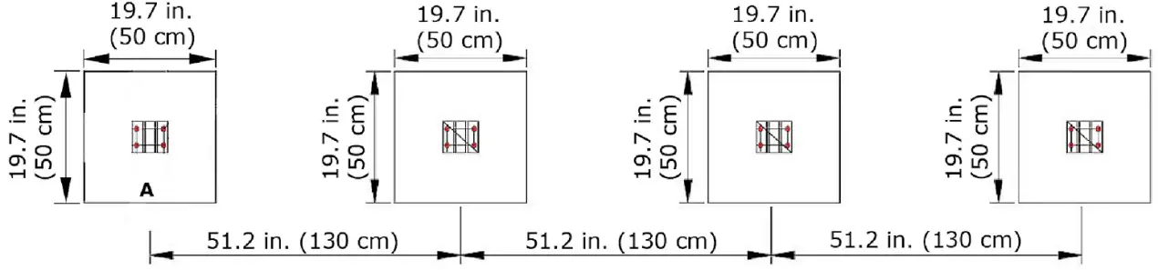
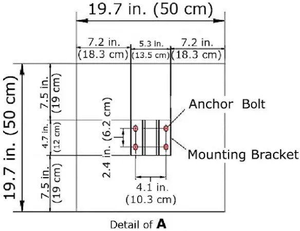

Use the provided anchor bolts to secure mounting brackets to the concrete anchors.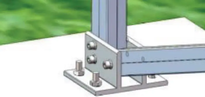
B) Rail Assembly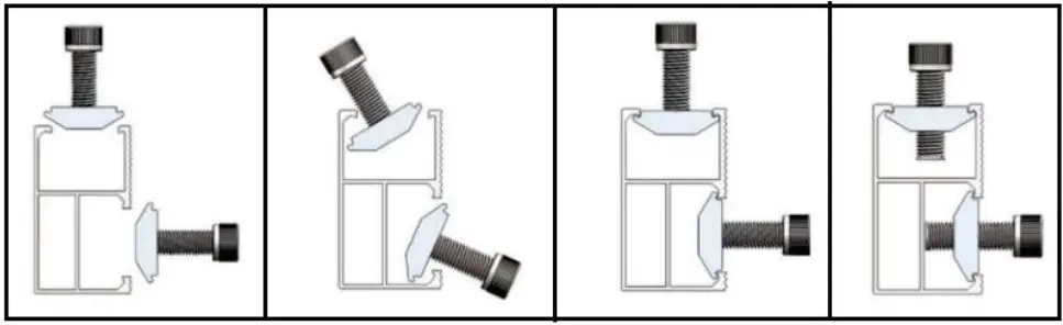
Follow the diagrams to secure the rails to the previously installed L feet. Use the splice connectors to join rail sections together, leaving a 0.1 – 0.2 in. (3 – 5 mm) expansion gap between rail joints.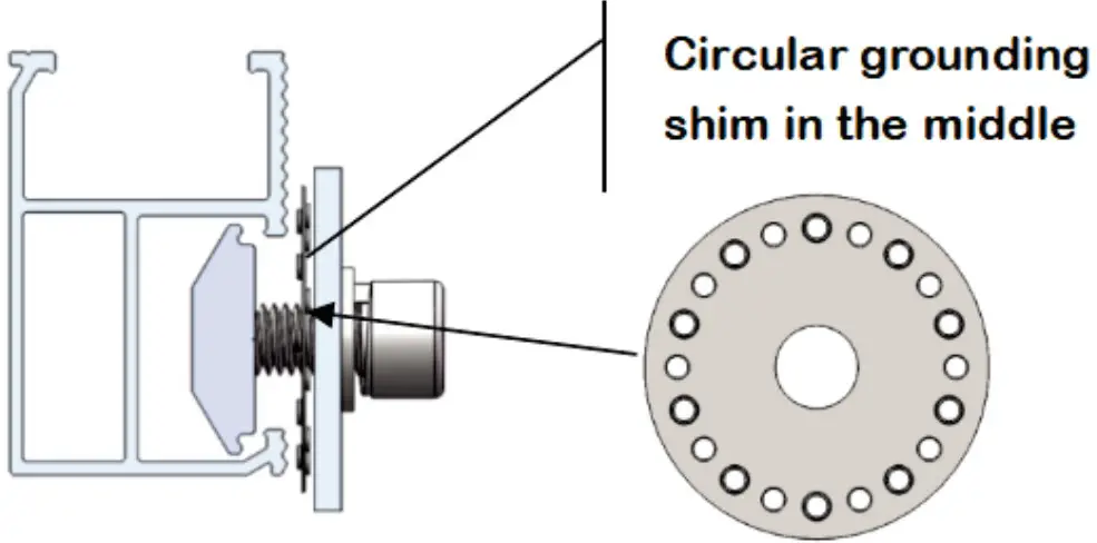
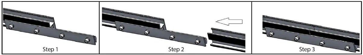
Completed rail assembly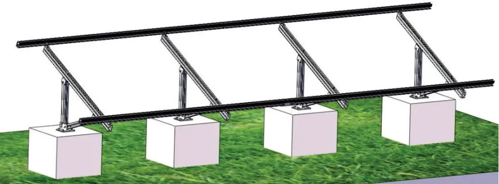
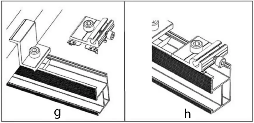
PV ATTACHMENT
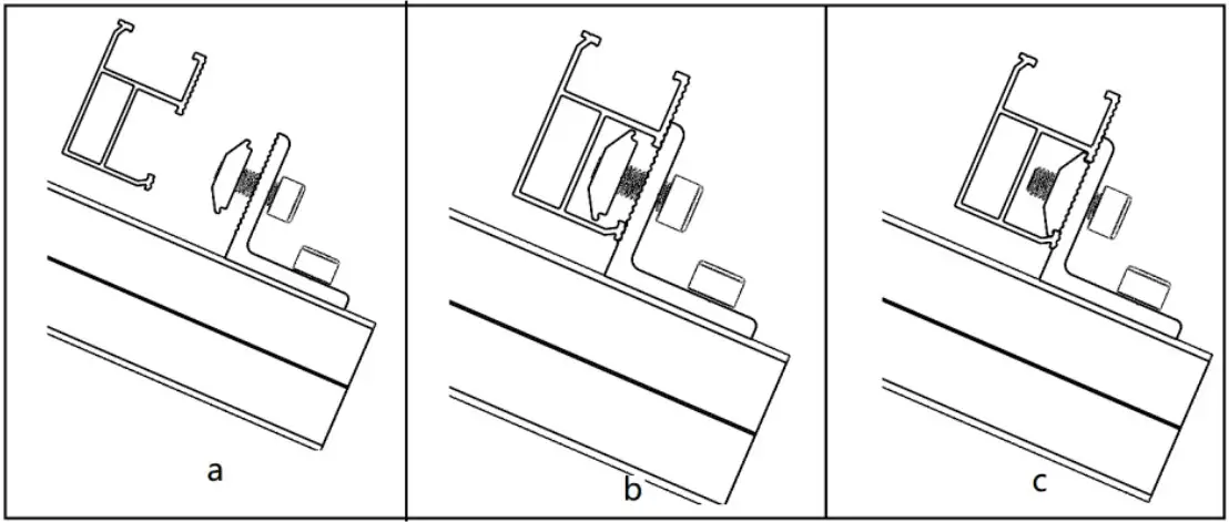
Install PV modules using the end clamps and mid clamps along with the grounding clips to secure them to the mounting rails. Follow the steps illustrated to the right for proper installation.
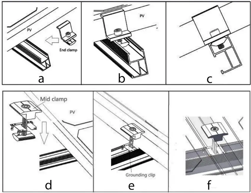
Install grounding lugs on the end of the rails to attach a grounding wire for proper array protection.