PV-ezRACK EzShade 2.0 Ground Mounting System for PV Installation Guide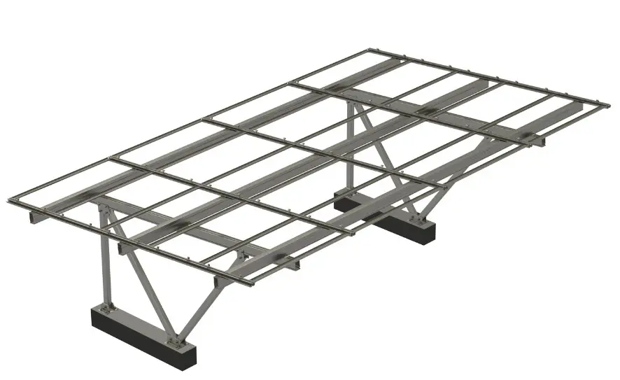
Introduction
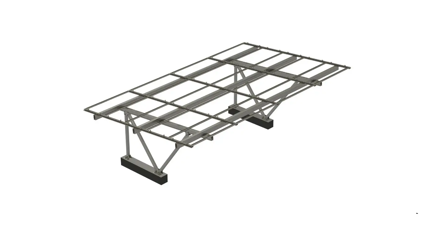
Clenergy PV-ezRack® ezShade 2.0 is a ground mounting system for PV installation in residential or commercial regions, and which is designed to create new spaces for solar energy while also providing shade for parking. The use of patented aluminium base rails, the Z-module technology and the splicing eliminate on site cutting and enables particularly fast installation.
Please review this manual thoroughly before installing ezShade 2.0. This manual provides the following contents: (1) Installation planning; (2) Installation instructions.
List of Contents
- Introduction :01
- Planning :02
- Tools &Components :03
- System Overview :05
- Installation Instruction :08
The PV-ezRack® ezShade 2.0 parts, when installed in accordance with this guide, will be structurally adequate and meet the GB50009- 2012,JIS8955, EURCODE 0-9, ASCE7-10, ISO 14713 standard. During installation, and especially when working on the ground, please comply with the appropriate occupational health and safety regulations. Please also pay attention to other relevant regulations in your local region. Please check that you are using the latest version of the installation manual by contacting Clenergy via email on [email protected] or contacting your local distributor.
The installer is solely responsible for:
- Comply with all applicable local or national building codes that may replace this manual;
- Ensure that ezRack and other products are appropriate for the particular installation and installation environment;
- Using only ezRack parts and installer-supplied parts as specified by ezRack (substitution ofM parts may void the warranty and invalidate the letter of certification);
- During construction, ensure that the foundation anchor bolts have sufficient strength and shear force;
- How to recycle: according to local regulations;
- How to disassemble: reverse installation process;
- Ensure that there are no less than two professionals working on the panel installation;
- Ensure the installation of the electrical quipment is performed by a professional and accredited electrician
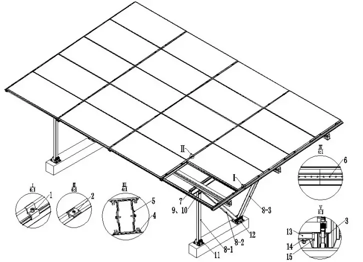
Planning
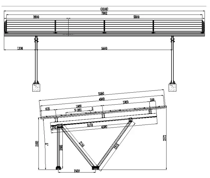
According to the figure above, applying PV module 1960x992x35mm, tilt angle 5 degree. The MAX height from the ground is 2572mm. The specific installation steps are as follows
Tools and Components
Installation Tools
- Allen Key 6mm (M8 hex socket screw)

- Electric Drill (ST6.3 selfdrilling screw and M8 hex socket screw)

- 5m Tape

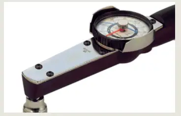
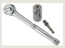
- Torque Wrench (M8/M12/M16)
- String

- Mark Pen

- Socket Wrench M8/M12

- Rubber hammer

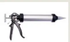
- Caulking Gun


Note: The tools shown are only for installation of support system (not included in the scope of supply), please contact the system installer for electronic component installation tools.
Components
- ER-EC-W40/OM LS Module End Clamp, with W module

- ER-ICII-W Inter Clamp II, with W module

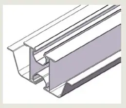
- R-SDII/60/5050 Rail 60*5050mm

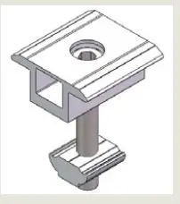
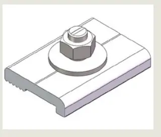
- ER-RC-T/W Rail Clamp for T-Raill with W module

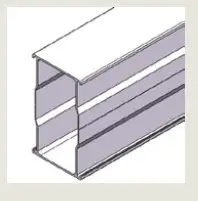
- R-SDII/168 Rail 168

- SP-SDII/R/168 Splice for Rail 168

- G-SDII/150/4300 Girder 150*4300

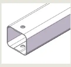
- RT-100/90 Rectangular Tube 100*90

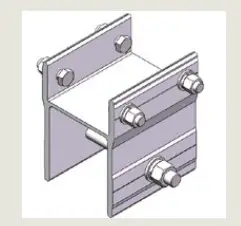
- HJ-SDII/158/130 H Joint 130
- HJ-SDII/158/240 H Joint 240
- BA-SDII/200 Corrugated T-Base 200

- BA-SDII/280 Corrugated T-Base 280

- GU-SDII/22/1913 Gutter 22*1913

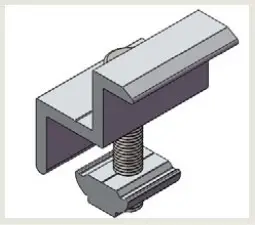
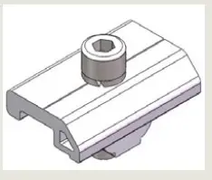
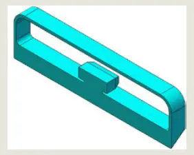
- C-SDII/50/35 Corrugated Clamp

- RR-GU/SDII/22 Rubber ring for Gutter 22

System Overview
- ER-EC-W40/OM, LS Module End Clamp, with W modul
- ICII-W40-42/A, Inter Clamp, with W module
- R-SDII/60/5050, Rail 60*5050mm
- ER-RC-T/W, Rail Clamp for T-Raill with W module
- R-SDII/168, Rail 168
- SP-SDII/R/168, Splice for Rail 168
- G-SDII/150/4300, Girder 150*4300
- RT-100/90, Rectangular Tube 100*90
- HJ-SDII/158/130, H joint 130
- HJ-SDII/158/240, H joint 240
- BA-SDII/200, Corrugated T-Base 200
- BA-SDII/280, Corrugated T-Base 280
- GU-SDII/22/1913, Gutter 22*1913
- C-SDII/50/35, Corrugated Clamp
- RR-GU/SDII/22, Rubber ring for Gutter 22
Precautions during Stainless Steel Fastener Installation
Improper operation may lead to deadlock of Bolts and Nuts. The below steps should be applied to every stainless steel nut and bolt assembly to reduce this risk.
Reduce the friction coefficient:
- Ensure that the thread surface is clean (no dirt or contaminant)
- Apply lubricant (grease or 40# engine oil) to fasteners prior tightening to avoid galling or seizing in the threads;
General installation instructions:
- Apply force to fasteners in the direction of thread;
- Apply force uniformly, to maintain required torque;
- Professional tools and tool belts are recommended, avoid using electric tools for final tightening;
- Avoid working at high temperatures,
Safe Torques
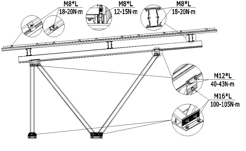
Note: Tighten the bolts after adjusting all components in place. Tightening and loosening bolts repeatedly will lead to deadlock of bolts.
Installation Dimensions
All drawings and dimensions in this installation guide are for a generic reference. The PV-ezRack® ezShade 2.0 is to be optimized to suit specific conditions for each project and documented in a construction drawing. As a result, major components of the PV ezRack® ezShade 2.0 may be provided in section sizes and lengths that vary from those shown in this guide. The installation process detailed in this instruction guide remains the same regardless of the component size. In case you need to do any on-site modifications or alteration of the system in a way that would be different from the construction drawing please provide marked up drawings/sketches for Clenergy’s review prior modification for comment and approval.
Installation Instruction
Post and Girder Installation
Prepare the required installation tools and products before installation.
As per engineering drawings, mark out the positions for bolts and embed 4pcs of M20 bolt in each position as shown in Figure 2.
Make sure all M20 bolts are aligned in both horizontal and vertical direction. All embedded bolts will be revealed 50±5mm above the ground as shown in Figure 1.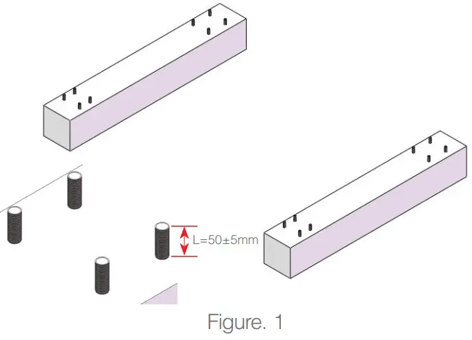
Note: The M20 bolts and matching nuts, washers and spring washers are provided by installer.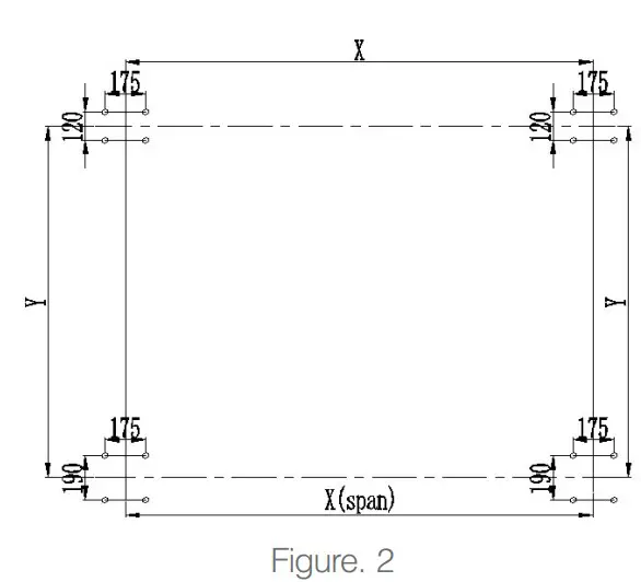
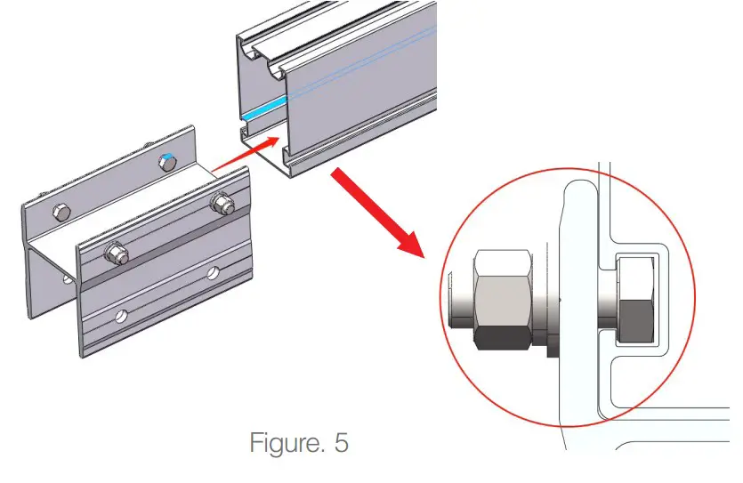
As shown in Figure 3, place bolts M12*35 into H Joint 130/240.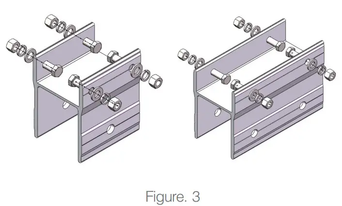
According to the engineering drawing, slide H Joint 130/240 to the corresponding position on the Girder and lock it as shown in Figure 4.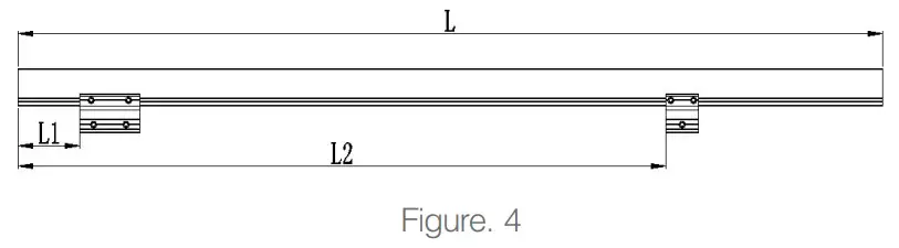
For sliding smoothly, to ensure the plane of the M12 bolt cap be parallel to the Girder slot surface when H Joints slide into the Girder, as shown in Figure 5.
Recommended torque for M12 bolts is 40-43N·m
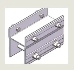
According to the engineering drawing, place different length Rectangular Tube 100*90 and T Base 200/280 by below steps, as shown in Figure 6.
- Place the Rectangular Tube L1 horizontally to align with the hole of H Joint 240 near the end of girder , place bushing in one hand and put on bolts M16*130 in the other hand, then put on flat washers, spring washers, nuts and lock manually.
- Laying down the Rectangular Tube L2, and follow step ① to complete the other hole installation of H Joint 240.
- Keep the Rectangular Tube flat, put the Tube L2 and Tube L3 into the Corrugated T-Base 280, align with the hole position, then put on bolts M16*150、bushings、flat washers、 spring washers and lock manually.
- Keep the Tube L1 flat, install the other hole with Corrugated T-Base 200.
- Laying down the support, rotate Tube L2 and Tube L3, align the hole of Tube L3 with the hole of H Joint130, put on bolts M16*130.

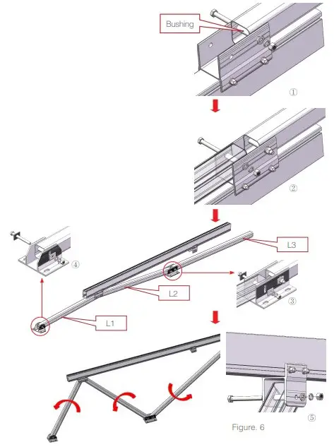
The above steps are all locked manually.
Note: Install the Trapezoidal Shim in the middle of the slot hole of the T-Base for subsequent adjustment
Keep all M16 bolt heads aligned.
The support is complete as shown in Figure 7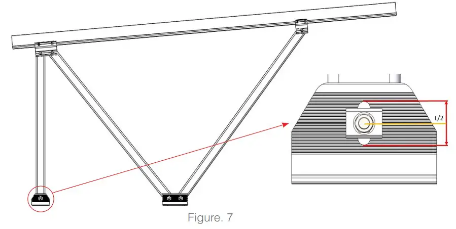
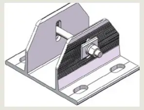
Insert the assembled support into embedded bolts .Align the embedded bolts with the holes on the T-Base, put on the spring washer, flat washer and nut, manual locking as shown in Figure 8.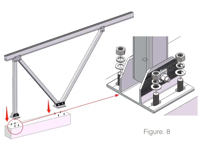
After placing an array support. Measure whether all the end faces and top surfaces are on the same plane and whether the installation angle meets the requirements. as Shown in Figure 9.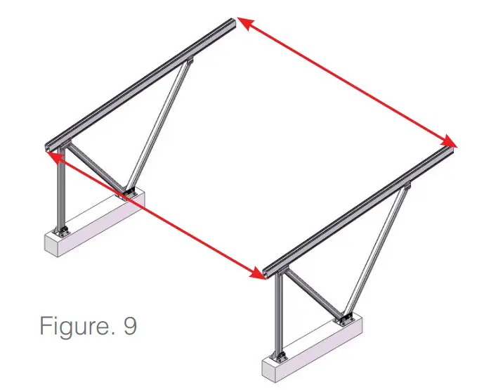
The adjustment range of the slot hole of T-Base as shown in Figure 10.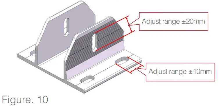
Fasten all bolts after adjustment.
Recommended torque for M16 bolts is 100-105 N·m, M20 is 200-220 N·m.
Rail 168 Installation
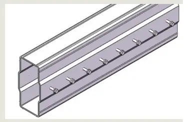
5.2.1 In order to form a longer section, first insert Splice halfway into end of T-Rail 168, and fasten by self-drilling screws as shown in Figure 11.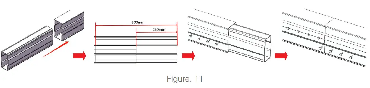
Note: The position of self drilling screw ST6.3*22 for connection as shown in Figure 12(unit:mm), total 16pcs on both sides. Tighten until the plastic pads are slightly compressed.
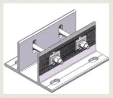
Place one T-Rail 168 on Girder as shown in Figure 13. Apply Rail Clamp to fix the T-Rail on Girder and fasten it by Allen Key.
Note: Apply two Rail Clamps for T-Rail on each side as shown in Figure 13
Recommended torque for M8 bolts is 18-20 N·m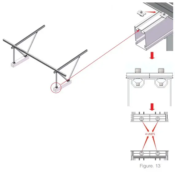
According to engineering drawings, repeat the above operations to install other T-Rails as shown in Figure 14.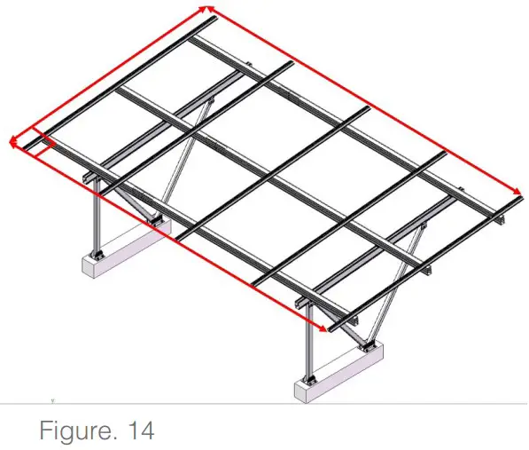
Note: Make sure every row of T-Rail is on the same horizontal line and the ends of the T-Rail are aligned.
Rail 60 Installation
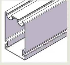
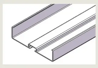
Place one Rail 60 with Water Channel on T-Rail 168 as shown in Figure 15.
Apply Rail Clamp to fix the Rail 60 on T-Rail and fasten it by Allen Key 6mm as shown in Figure 16.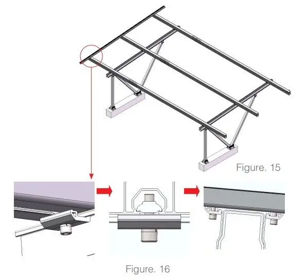
According to engineering drawings, repeat the above operations to install ohter Rail 60 with Water Channels as shown in Figure 17.
Note: Make sure every row of the Rail is on the same vertical line and the ends of the Rail are aligned.
Recommended torque for M8 bolts is 18-20N·m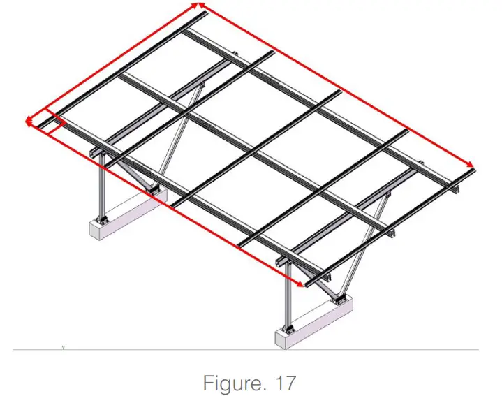
PV Module Installation
Click the pre-assembled End Clamp or Inter Clamp II into the grooves of the Rail 60 with Water Channel as shown in Figure 18.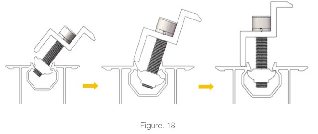
According to the Figure, place the first row of PV Module on the Rail 60 with Water Channel one by one. The order of the PV Module is from low to high, and from left to right as shown in Figure 19.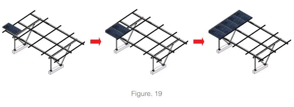
Note: Make sure each row of PV Moudle mantains the gap of 2mm, it’s recommended to make a T-plate with a thickness of 2mm for measurement. The PV Modules are attached closely with the Rails, and the ends of PV Module are aligned. Then fasten Inter Clamps and End Clamps as shown in Figure 20.
Recommended torque for M8 bolts is 18-20N·m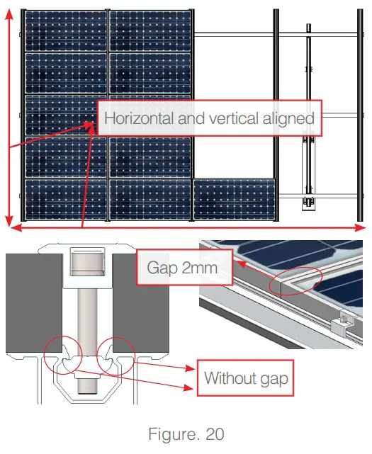
Gutter Installation
Slide two sets of Corrugated Clamps into the bottom of the Gutter, and do not fasten the bolts as shown in Figure 21.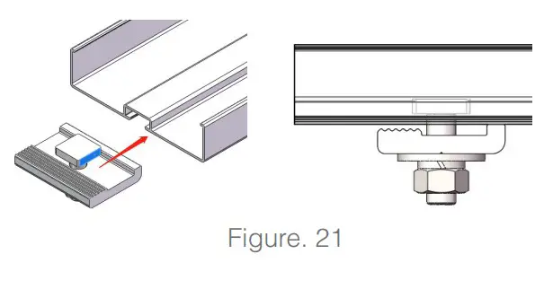
Put the Rubber Ring into the Gutter and plug the bottom slot. Ensure the Rubber Ring is aligned with the ends of Gutter. Glue evenly the connection as shown in Figure 22.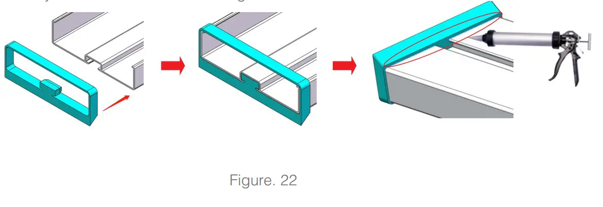
The effect of installation among Gutter, Corrugated Clamp and Rubber Ring as shown in Figure 23.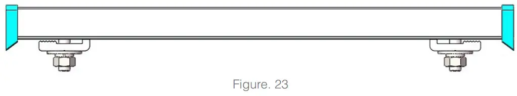
Tilt the Gutter , and place it between the bottom of the PV Module and the Rail 60 with Water Channel as shown in Figure 24 .The order of the Gutter is the same as the PV Module, from low to high, and from left to right.
Straighten the Gutter, make sure the centre of the Gutter is parallel to the frame line of PV Module and downward by about 10mm as shown in Figure 24. Figure. 24 Figure. 25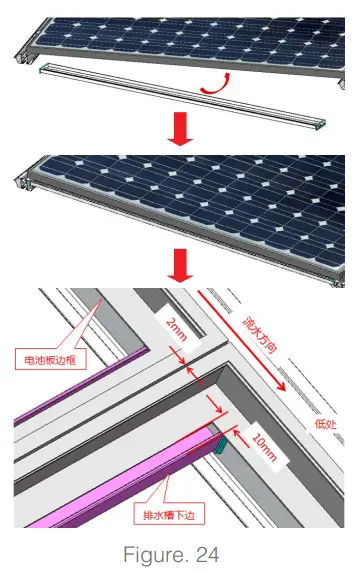
Note: The distance of the two ends of Gutter over the Water Guide Rail60 is equal as shown in Figure 25.
After the last step, adjust Corrugated Clamp to engage the corrugated surface of Rail 60 with Water Channel and the clamp are Meshed, then lock the Corrugated Clamp as shown in Figure 25.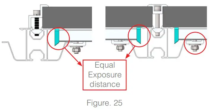
Recommended torque for M8 bolts is 12-15N·m
After placing an array of Gutter as shown in Figure 26, make sure the Gutters in each row are on the same line.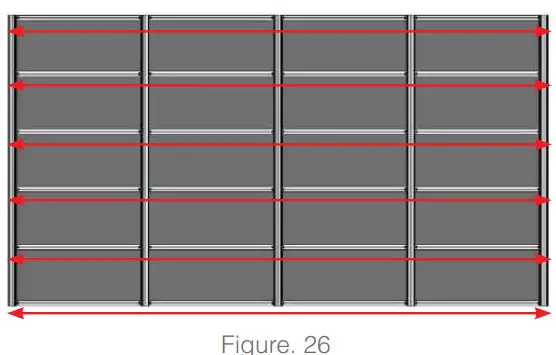
After the installation is completed, check to ensure all bolts are locked, and the installation is complete as shown in Figure 27.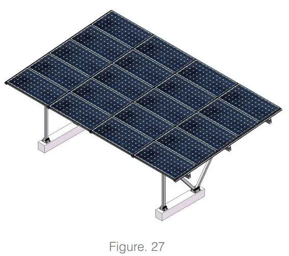
Grounding Clip(GC-LSR)
A. The red frame is the installation position of the Grounding Clip(GC-LSR)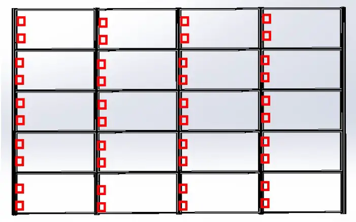
B. The installation location is as shown below:
1 panel matchs 2 Grounding Clip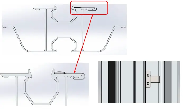
Grounding Lug(EZ-GL-U)
Installed on the high side/’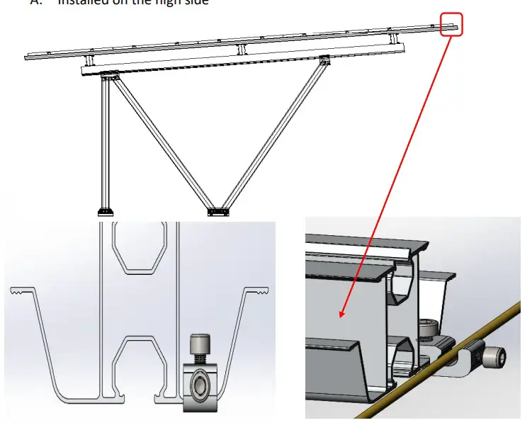
B. 1 Rail-60(R-SDII/60/L) matchs 1 Grounding Lug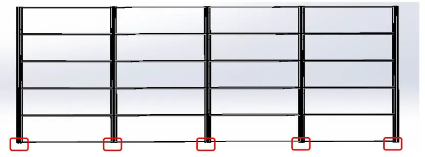
Clenergy Australia
1/10 Duerdin Street, Clayton VIC 3168 Australia
Tel: +61 3 9239 8088 Fax: +61 3 9239 8024
E-mail: [email protected]
www.clenergy.com.au
Clenergy China
999-1009 Min’an Rd, Huoju Hi-tech Ind. Dev. Zone
Xiang’an District 361101, Xiamen, Fujian, China
Tel: +86 592 311 0088 Fax: +86 592 599 5028
E-mail: [email protected]
www.clenergy.com.cn
Clenergy EMEA
Esplanade 41, 20354 Hamburg, Germany
Tel: +49 (0) 40 3562 389 00
E-mail: [email protected]
Clenergy Japan
Nittochi Yamashita Building 5th Floor
23 Yamashita-cho, Yokohama, 231-0023 Japan
Tel: +81 45 228 8226 Fax: +81 45 228 8316
E-mail: [email protected]
www.clenergy.jp
Clenergy Philippines
145 Yakal St., San Antonio village, Makati City, Philippines
Tel: +63 977 8407240
E-mail: [email protected]
www.clenergy.ph
Clenergy Thailand
9/2, 5th Floor, Vorasin Building, Soi Yasoob 2, Viphavadee-Rungsit
Road, Chomphon Sub-district, Chatuchak District, Bangkok 10900
Tel: +66 (0) 2 277 5201, +66 (0) 6 3228-0200
E-mail: [email protected], [email protected]
www.clenergythailand.com
Clenergy Singapore
24 Raffles Place #28-01 Clifford Centre Singapore 048621
Tel: +65 9743 1425
E-mail: [email protected]
Clenergy Malaysia
Tel: +86 18750231005
E-mail: [email protected]
Clenergy Vietnam
Tel: +86 592 3110095
E-mail: [email protected];
[email protected]
Clenergy Korea
Tel: +8210-4684-8088
E-mail: s[email protected]
References
 清源股份|跟踪/固定/工商业/户用光伏解决方案 |智慧光伏 + 数字能源管理解决方案
-
Home | Clenergy | Solar Racking | Cable Management | PV mountings | Fasten your solar panels to the Rooftop or ground
-
清源股份|跟踪/固定/工商业/户用光伏解决方案 |智慧光伏 + 数字能源管理解决方案
 Home | 株式会社クリーンエナジージャパン | 太陽光発電架台 | ケーブル管理システム |
-
Clenergy - Solar Mounting & Cable Management Manufacturer
-
Clenergy - Solar Mounting & Cable Management Manufacturer


