
EZ SOLAR JB-1.XL Rooftop PV Junction Box
Product Information
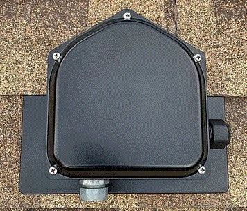
JB-1.XL Rooftop Junction Box
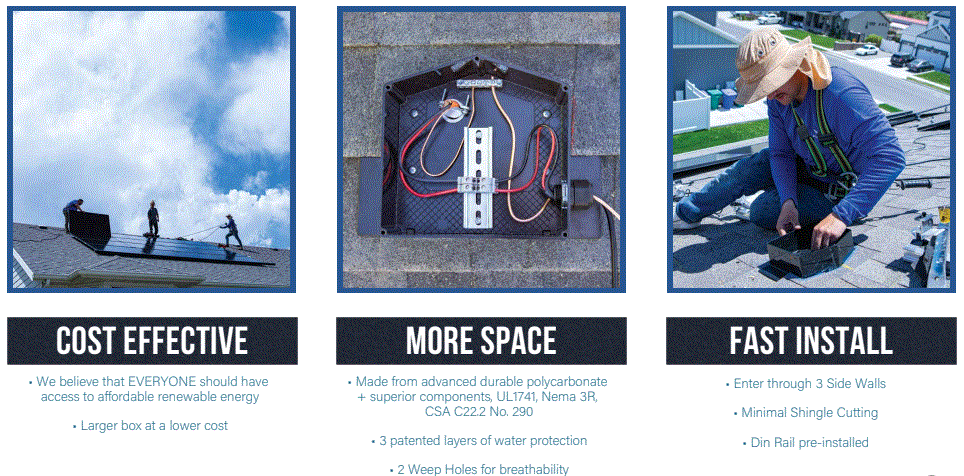
The JB-1.XL is a rooftop junction box designed for use with composition/asphalt shingle roofs. It is a cost-effective optionthat provides more space and fast installation. The JB-1.XL is UL1741 and CSA C22.2 No. 290 approved, and it requires wire connectors that conform to the same standards. The JB-1.XL is equipped with ABB ZS6, ZS10, and ZS16 terminal blocks, as well as Ideal 452 Red Wing-Nut, Ideal 451 Yellow Wing-Nut, Ideal In-Sure Push-In Connector Part #39, WAGO 2204-1201, WAGO 221-612, Dottie DRC75, ESP NG-53, and ESP NG-717 wire connectors. The JB-1.XL is suitable for use with various wire sizes and has different torque loads and ratings depending on the connector type.
Product Usage Instructions
Before installing the JB-1.XL rooftop junction box, ensure that you have the right wire connectors that conform to UL1741 and CSA C22.2 No. 290 standards. Then, follow these steps:
- Choose a suitable location for the JB-1.XL rooftop junction box on your composition/asphalt shingle roof.
- Ensure that there is enough space for the conductors to pass through a wall opposite the terminals.
- Install the ABB ZS6, ZS10, or ZS16 terminal block in the JB-1.XL rooftop junction box, depending on your wire size and bending space requirements.
- Select the appropriate wire connector from the list of approved connectors and connect the wires to the terminal blocks.
- Ensure that the wires are properly secured and that there is no contact between components of opposite polarity.
- Check the torque loads and ratings for your wire connector type and tighten the connections accordingly.
- Test the system for proper operation and replace any affected components immediately.
For more information or assistance, contact ezsolarproducts.com at [email protected] or call 385.202.4150.
INTRODUCING JB-1.XL Specification Sheet
 Specification Sheet
PV Junction Box for Composition/AsphaIt Shingle Roofs
A. System Specifications and Ratings Maximum Voltage:
- Maximum Voltage: 1,000 Volts
- Maximum Current: JB-1.2: 80 Amps; JB-1.XL: 120 Amps
- Allowable Wire: 14 AWG – 6 AWG
- Spacing: Please maintain a spacing of at least ½” between uninsulated live parts and fittings for conduit, armored cable, and uninsulated live parts of opposite polarity.
- Enclosure Rating: Type 3R
- Roof Slope Range: 2.5 – 12:12
- Max Side Wall Fitting Size: 1”
- Max Floor Pass-Through Fitting Size: 1”
- Ambient Operating Conditions: (-35°C) – (+75°C)
- Compliance:
- JB-1.2: UL1741, CSA C22.2 No. 290; JB-1.XL: UL1741, CSA C22.2 No. 290
- Approved wire connectors: must conform to UL1741, CSA C22.2 No. 290
- System Marking: Interek Symbol and File #5019942
- Periodic Re-inspections: If re-inspections yield loose components, loose fasteners, or any corrosion between components, components that are found to be affected are to be replaced immediately.
Table 1: Typical Wire Size, Torque Loads and Ratings
| 1 Conductor | 2 Conductor | Torque | |||||
| Type | NM | Inch Lbs | Voltage | Current | |||
| ABB ZS6 terminal block | 10-24 awg | 16-24 awg | Sol/Str | 0.5-0.7 | 6.2-8.85 | 600V | 30 amp |
| ABB ZS10 terminal block | 6-24 awg | 12-20 awg | Sol/Str | 1.0-1.6 | 8.85-14.16 | 600V | 40 amp |
| ABB ZS16 terminal block | 4-24 awg | 10-20 awg | Sol/Str | 1.6-2.4 | 14.6-21.24 | 600V | 60 amp |
| ABB M6/8 terminal block | 8-22 awg | Sol/Str | .08-1 | 8.85 | 600V | 50 amp | |
| Ideal 452 Red WING-NUT Wire Connector | 8-18 awg | Sol/Str | Self-Torque | Self-Torque | 600V | ||
| Ideal 451 Yellow WING-NUT Wire Connector | 10-18 awg | Sol/Str | Self-Torque | Self-Torque | 600V | ||
| Ideal, In-Sure Push-In Connector Part #39 | 10-14 awg | Sol/Str | Self-Torque | Self-Torque | 600V | ||
| WAGO, 2204-1201 | 10-20 awg | 16-24 awg | Sol/Str | Self-Torque | Self-Torque | 600V | 30 amp |
| WAGO, 221-612 | 10-20 awg | 10-24 awg | Sol/Str | Self-Torque | Self-Torque | 600V | 30 amp |
| Dottie DRC75 | 6-12 awg | Sol/Str | Snap-In | Snap-In | |||
| ESP NG-53 | 4-6 awg | Sol/Str | 45 | 2000V | |||
| 10-14 awg | Sol/Str | 35 | |||||
| ESP NG-717 | 4-6 awg | Sol/Str | 45 | 2000V | |||
| 10-14 awg | Sol/Str | 35 | |||||
| Brumall 4-5,3 | 4-6 awg | Sol/Str | 45 | 2000V | |||
| 10-14 awg | Sol/Str | 35 | |||||
Table 2: Minimum wire-bending space for conductors through a wall opposite terminals in mm (inches)
| Wire size, AWG or kcmil (mm2) | Wires per terminal (pole) | ||||||
| mm | 1 | (inch) | 2 mm (inch) | 3 mm (inch) | 4 or More mm (inch) | ||
| 14-10 | (2.1-5.3) | Not Specified | – | – | – | ||
| 8 | (8.4) | 38.1 | (1-1/2) | – | – | – | |
| 6 | (13.3) | 50.8 | (2) | – | – | – | |
ezsolarproducts.com | [email protected] | 385.202.4150


