![]()
![]() 21 100 801 – 1
21 100 801 – 1
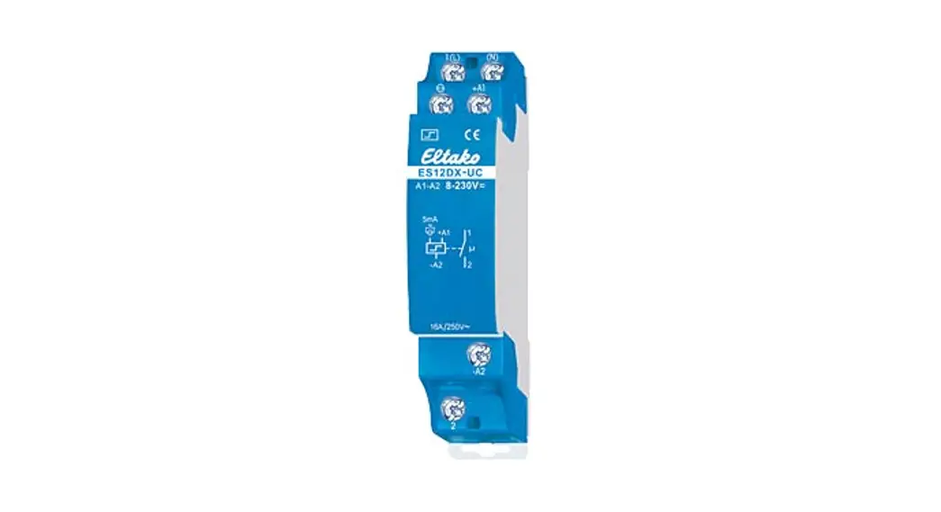
Impulse switch
ESW12DX-UC
Only skilled electricians may install this electrical equipment otherwise there is the risk of fire or electric shock!
The temperature at the mounting location: -20°C up to +50°C.
Storage temperature: -25°C up to +70°CRelative humidity: annual average value <75%.
1 NO contact potential free 16 A/250 V AC with tungsten pre-contact. 230 V LED lamps up to 600 W, incandescent lamp load 3300 W. Max. inrush current 500 A/2 ms.
No standby loss.
Modular device for DIN-EN 60715 TH35 rail mounting. 1 module = 18 mm wide, 58 mm deep.
State-of-the-art hybrid technology combines the advantages of nonwearing electronic control with a high capacity of special relays.
With the patented Eltako Duplex technology (DX) the normally potential-free contacts can still switch in zero passage when switching 230 V AC 50 Hz and therefore drastically reduce wear. Simply connect the neutral conductor to the terminal (N) and L to 1 (L) for this. This gives an standby consumption of only 0.1 Watt.
Universal control voltage 8 to 230 V UC. Low switching noise.
No permanent power supply is necessary, therefore no standby loss.
By using a bistable relay coil power loss and heating is avoided even in the on mode.
The relay contact can be open or closed when put into operation. It will be synchronized at first operation.
The electronics do not have an internal power supply and therefore no power is consumed in any contact position. A control current flows only during a short control impulse of 0.2 seconds. This activates the microcontroller, reads the last switching state from the non-voltage memory, switches the bistable relay to its opposite state accordingly and rewrites the new switching state to memory.
Typical connections
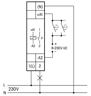
with zero passage switching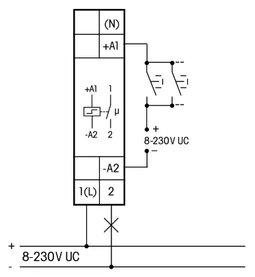
without zero passage switching
Technical data
| 230 V LED lamps | up to 200 W 2) with DX up to 600 W 2) I on ≤ 500 A/5 ms |
| Control voltage AC | 8..253 V |
| Control voltage DC | 10..230 V |
| Rated switching capacity | 16 A/250 V AC |
| Incandescent lamp load and halogen lamp load 1) 230 V | 3300 W |
| Fluorescent lamp load with KVG* in lead-lag circuit or non compensated | 1000 VA |
| Fluorescent lamps with KVG* shunt-compensated or wih EVG* | 500 VA |
| Standby loss | none |
* EVG = electronic ballast units;
KVG = conventional ballast units
- For lamps with 150 W max.
- Due to different lamp electronics and depending on the manufacturer, the maximum number of lamps may be limited, especially if the wattage of the individual lamps is very low (e.g. with 2 W LEDs).
![]() The strain relief clamps of the terminals must be closed, which means the screws must be tightened for testing the function of the device. The terminals are open ex-works.
The strain relief clamps of the terminals must be closed, which means the screws must be tightened for testing the function of the device. The terminals are open ex-works.
Must be kept for later use!
We recommend the housing for operating instructions GBA14.
Eltako GmbH
D-70736 Fellbach
Technical Support English: ![]() +49 711 94350025
+49 711 94350025![]() [email protected]
[email protected]
eltako.com
41/2021 Subject to change without notice.


