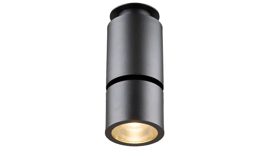
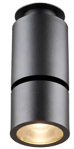
Anolis HP111 Ambiane Surface Mount
INSTALLATION INSTRUCTIONS
AMBIANE HP111 SURFACE MOUNT
- STEP 1
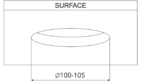
- CEILING OPENING
 Standard mounting hole with diameter of 100-105mm.
- CEILING OPENING
- STEP 2
- MOUNTING OF CONTROL UNIT
 Place control unit above the ceiling through the ceiling opening.
 Mount the control unit to ceiling via two mounting holes and suitable fasteners.
- MOUNTING OF CONTROL UNIT
- STEP 3
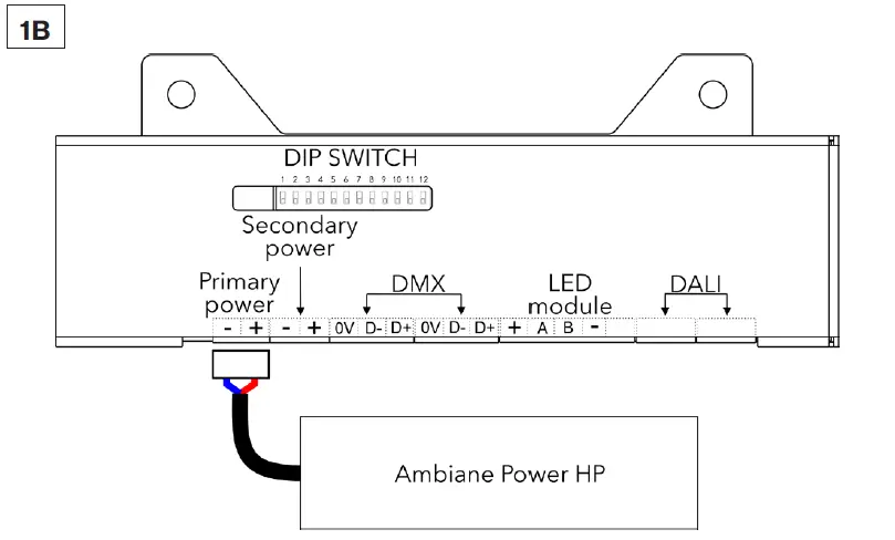
- PRIMARY POWER CONNECTION


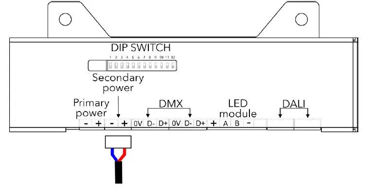
Install terminal block to power cable (from Ambiance Power Rack or Ambiance Power HP) and connect it to Primary power socket of the control unit.
- PRIMARY POWER CONNECTION
- STEP 4
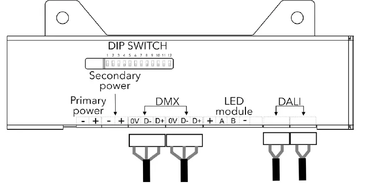
- DATA CABLES CONNECTION (DMX OR DALI)
DMX CONNECTION0V D- D+ Data Ground Data – Data + Install terminal blocks on DMX or DALI data cables and conne-ct them to the control unit.
Set the DIP switches to positions according to your operation mode. The fixture can be controlled by DMX or DALI (switch 11 in OFF position).
- DATA CABLES CONNECTION (DMX OR DALI)
- STEP 5
- SECONDARY POWER CABLE CONNECTION 48V (PSU SCOPE OF OTHERS)
 Install terminal block on Secondary power cable and connect it to Secondary power socket of the control unit.
- SECONDARY POWER CABLE CONNECTION 48V (PSU SCOPE OF OTHERS)
- STEP 6
- LED UNIT CONNECTION
- Shorten power/data cable of LED unit to required length.
- Strip these lengths of LED unit‘s cable for wiring connection.
 LED Unit Connection
TERMINAL BLOCK + A B – Color of Wire Red White Blue Black  Install terminal block on LED unit‘s cable and connect it to the control unit.
 Connected luminaire before installation.
LED unit connected to control unit prior to mounting.
- LED UNIT CONNECTION
- STEP 7
- MOUNTING OF LUMINAIRE
- Max. possible thickness of a ceiling material is 20 mm.
 Insert the fixture into the ceiling mounting hole.
 Spread the holders and tighten them up with Allen key as illustrated.
 Tighten the holders on both sides until the fixture is firmly se-cured to the ceiling.
- Max. possible thickness of a ceiling material is 20 mm.
- MOUNTING OF LUMINAIRE
- STEP 8
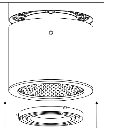
- INSTALLATION OF ACCESSORIES RING LOUVER FOR 20° REFLECTOR

Insert the Ring Louver into the Top frame.
- INSTALLATION OF ACCESSORIES RING LOUVER FOR 20° REFLECTOR
 Standard mounting hole with diameter of 100-105mm.
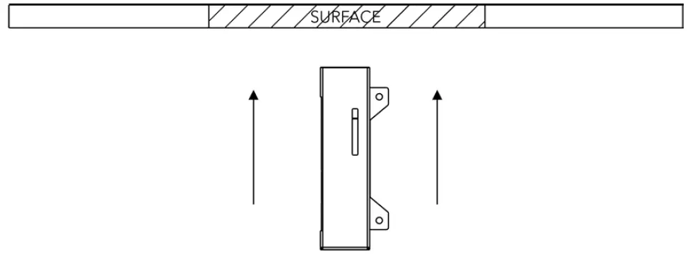 Place control unit above the ceiling through the ceiling opening.
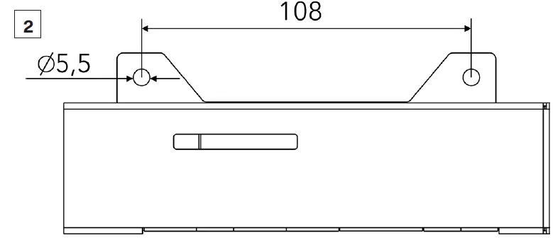 Mount the control unit to ceiling via two mounting holes and suitable fasteners.
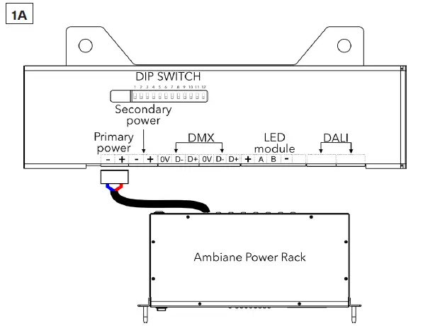
 Install terminal block on Secondary power cable and connect it to Secondary power socket of the control unit.
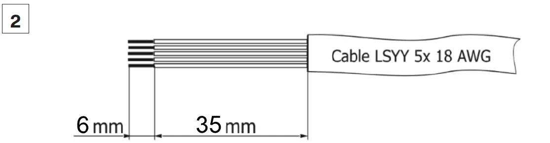 LED Unit Connection
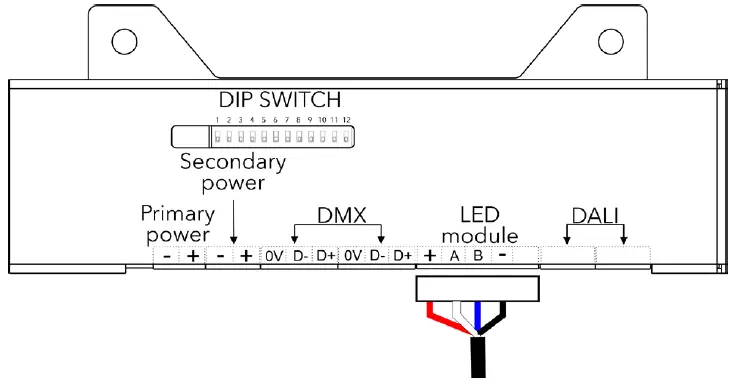 Install terminal block on LED unit‘s cable and connect it to the control unit.
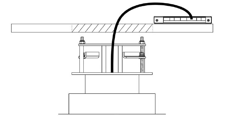 Connected luminaire before installation.
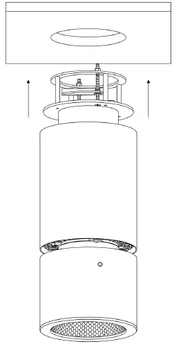 Insert the fixture into the ceiling mounting hole.
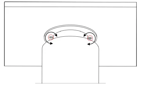 Spread the holders and tighten them up with Allen key as illustrated.
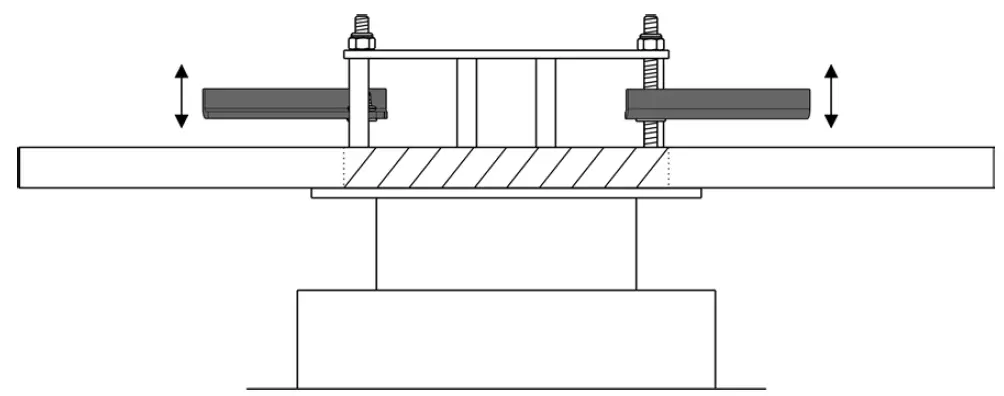 Tighten the holders on both sides until the fixture is firmly se-cured to the ceiling.
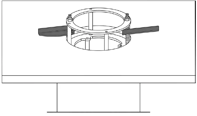
ROBE lighting s. r. o. |
Palackeho 416 |
757 01 Valasske Mezirici |
Czech Republic |
Tel.: +420 571 751 500 |
E-mail: [email protected] |
www.anolislighting.com
VERSION 1.0 / 04_2022


