
Ambiane HP111 Recessed Anolis LED Lighting
Attention
- The unit must be installed by a qualified electrician in accordance with all national and local electrical and construction codes and regulations.
- The unit was designed for indoor use only.
- Do not install the unit near highly inflammable liquids or materials.
- Do not allow anything to rest on the unit.
- Do not install the unit near an open flame.
- Do not install the unit in dirty, dusty or badly ventilated location.
- Avoid looking directly into the light beam at close range!
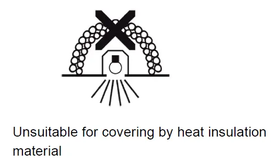
- A ceiling (structure) intended for installation of the unit(s) must safely hold at least 5 times the weight of the unit(s)
- fastened on it. Sufficient air accessing to the housing of the unit has to be ensured, there must not be any heat or anti-noise insulation).
Immunity of the equipment is designed for electromagnetic environments E1, E2, E3 according to the standard EN55103-2 ed.2 Electromagnetic compatibility. Product family standard for audio, video, audiovisual and entertainment lighting control apparatus for professional use.
Part 2: Immunity. The product (covers and cables) must not be exposed to a high frequency electromagnetic field higher than 3V/m. The installation company should check levels of possible interferences above the tested levels E1,E2,E3 given by this standard (e.g. transmitters in surrounding area) before installing the equipment. Emission of the equipment complies with the standard EN55032 Electromagnetic compatibility of multimedia equipment – Emission Requirements according to class B.
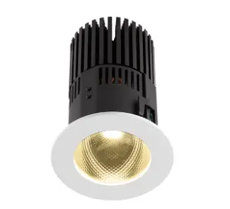
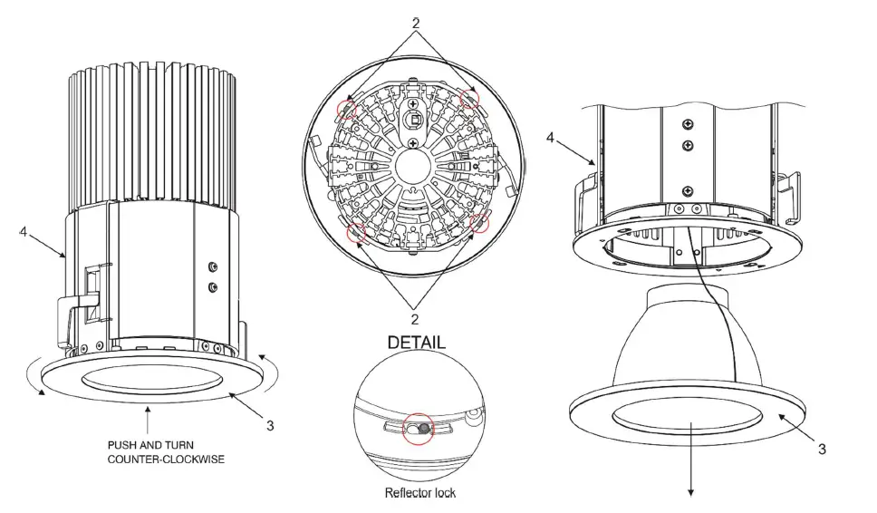
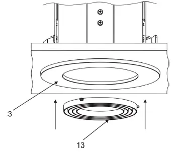
Fixture exterior view
Installation
The Ambiane HP111 Recessed must be installed by a qualified electrician in accordance with all national and local electrical and construction codes and regulations. Always switch off power supply of the control unit before connecting or disconnecting the control unit or the LED unit. The lower ceiling (or another structure) intended for installation of the Ambiane(s) HP111 Recessed must safely hold at least 5 times weight of the Ambiane(s) HP111 Recessed placed on it.
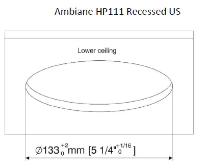
- Prepare a circular opening in the lower ceiling.

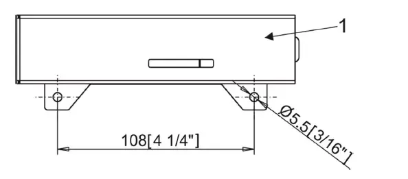
- Fasten the control unit (1) on the ceiling by means of two holes in the housing of the control unit.

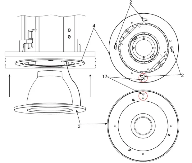
- Remove the frame with reflector (3) from the Ambiane HP111 housing (4) by pushing and turning the frame with reflector (3) counter-clockwise. The frame with reflector (3) is fastened in the housing by means of four locks (2).

- Install the terminal block (5) on the supply cable connect it to the PCB RB 3729 of the control unit (1).
- Install the terminal block (6) on the DMX cable and connect it to the PCB RB 3729 of the control unit (1).
- Install the terminal block (7) on the LED unit cable and connect it to the PCB RB 3729 of the control unit (1).
- Install another terminal blocks on cables according to requirements of current installation.
Example of connection:
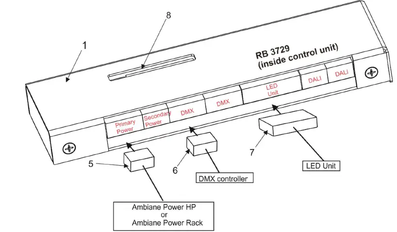
The DIP switch (9) is accessible by the aperture (8) in the cover of the control unit (1).
LED unit connection (cable LSYY 5×18 AWG)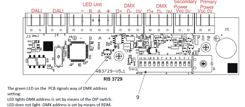
| Connector | + | A | B | – |
| Function | LEDs + | Data A | Data B | LEDs – |
| Colour of wire | Red | White | Blue | Black |
Strip these lengths for cable connections.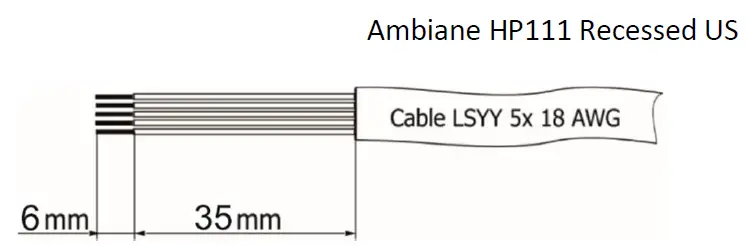
Primary power connection
| Connector | Vcc | 0V |
| Function | Power + | Power – |
Recommended diameters of conductors with respect to distance between the Control unit and the power supply (e.g. Ambiane Power HP):
| Distance/cable length | 25 m | 50 m | 75 m | 100 m |
| Diameters of conductors | 0.5 mm2 | 1 mm2 | 1.5 mm2 | 2 mm2 |
Secondary power connection
| Connector | Vcc | 0V |
| Function | Power + | Power – |
DMX connection
| Connector | D+ | D- | 0V |
| Function | Data + | Data- | Data ground (shielding) |
0-10V connection
| Connector | D+ | 0V |
| Function | +10V | 0V |
DMX connectors are used for 0-10V control.
Primary and secondary power.
The primary power input serves for a standard power (e.g. Ambiane Power HP). The secondary power input serves for a backup power (in case that primary power failed) – emergency mode. If both power inputs are under voltage, the primary power has a priority and the secondary power is disabled. In case of primary power loss, the secondary power is enabled. If the fixture is supplied via the secondary power, the light output of the fixture is a white colour (3200K). Max. operating time for secondary power (emergency mode) is 3 hours.
Set the DIP switch (9) according to your operation mode. This DIP switch is accessible by aperture (8) in the cover of the control unit (1). The fixture can be controlled by one of the following methods: DMX 512. The fixture is equipped with two DMX and DALI connection blocks (on the PCB RB 3729) for easy connection to a DMX or DALI chain (In/Out method).
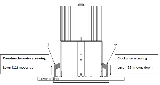
After connecting needed cables to the control unit, insert the LED unit (4) into prepared hole in the lower ceiling and screw two adjusting screws (11) in order to slide and support the levers (12) against surface (lower ceiling).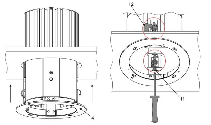
Insert the frame with reflector (3) to the Ambiane HP111 housing (4) and push and turn it clockwise until it snaps into locks (2) in the Ambiane HP111 housing (4).
Important. The positions of the triangle marks (12) have to be opposite each other before inserting and turning the frame with reflector (3).
Ambiane HP111 Recessed US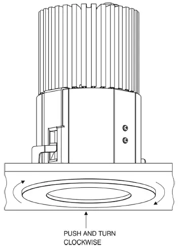
Snap the ring louver (13) to the frame with reflector (3).
Note: the ring louver is optional accessories.
DMX and DALI address setting and control
The DIP switch on the control PCB (RB3729) allows you to set DMX address and run a test light.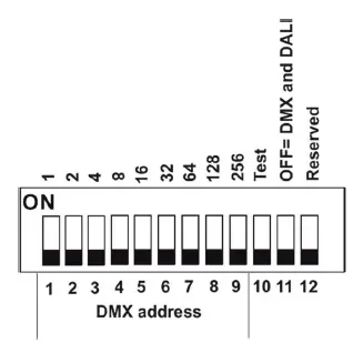
DIP 10 – if it is switched to ON=test light (the fixture lights at 3200K (for RGBW and TW version))
DIP 11 – has to be switched to OFF position to receive DMX 512 and DALI, position ON=0-10V control
Note: If DIP 11=OFF (fixture is controlled by DMX and DALI), the last coming command switches the fixture to the corresponding operation mode (DMX operation by a DMX command, DALI operation by a DALI command). E.g. the fixture stays in a DALI operation and last coming command is a DMX command which switches the fixture to DMX operation. Next command is a DALI command and switches the fixture to the DALI operation etc. If you need the permanent DALI operation, you have to send a DALI command 8 to the fixture.
DMX control
The DMX start address, is the first channel used to receive instructions from the DMX controller. The address may be any channel from 1 to 512. DMX address can be set either by DIP switch or by RDM. DMX address set by RDM overwrites address set by DIP switch and vice versa. The green LED on PCB signals way of DMX address setting:
LED lights-DMX address is set by means of the DIP switch.
LED does not light-DMX address is set by means of RDM. The DIP 11 has to be set to OFF position.
Example of DMX addresses: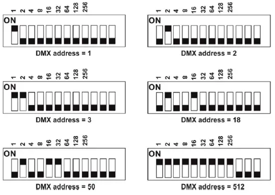
DALI control
Addressing of the fixture has to be made by means of an external DALI controller. If you need to start the permanent DALI control of the fixture (fixture will not respond to DMX commands), the external DALI controller has to send activating command (8=ON). If you need to stop the permanent DALI control of the fixture, the external DALI controller has to send deactivating command (0=OFF).
0-10V control
DIP 11 has to be set in ON position. 0-10V operation has priority to DALI and DMX commands. The option is applicable for the PW and TD version of the Ambiane HP111 only.
RDM
This fixture supports RDM operation. RDM (Remote Device Management) is a bi-directional communication protocol for use in DM X512 control systems, it is the new open standard for DMX512 device configuration and status monitoring. RDM allows you to set a DMX address, select DMX mode, readout software version of the fixture etc. It is also used for fixture software update by means of the Robe Uploader.
RDM model ID for the Ambiane HP111 Recessed 0x0114.
| Parameter ID | Discovery command | SET command | GET command |
| DISC_UNIQUE_BRANCH | * | ||
| DISC_MUTE | * | ||
| DISC_UN_MUTE | * | ||
| DEVICE_INFO | * | ||
| SUPPORTED_PARAMETERS | * | ||
| SOFTWARE_VERSION_LABEL | * | ||
| DMX_START_ADDRESS | * | * | |
| IDENTIFY_DEVICE | * | * | |
| DEVICE_MODEL_DESCRIPTION | * | ||
| MANUFACTURER_LABEL | * | ||
| DEVICE_LABEL | * | * | |
| DMX_PERSONALITY | * | * | |
| DMX_PERSONALITY_DESCRIPTION | * | ||
| RESET_DEVICE | * | ||
| SENSOR_VALUE | * | * | |
| SENSOR_DEFINITION | * |
| SLOT_INFO | * | ||
| SLOT_DESCRIPTION | * | ||
| DEFAULT_SLOT_VALUE | * | ||
| PARAMETER_DESCRIPTION | * |
DMX protocols
Variant RGBW, version 1.0
| Mode 1 Channel | Mode 2 Channel | Mode 3 Channel | Mode 4 Channel | Mode 5 Channel | DMX value | Function | Type of control |
| 1 | 1 | 1 | – | 1 | 0-255 | Red Red LEDs saturation control (0–>100%) | proportional |
| – | – | 2 | – | – | 0-255 | Red Fine Red LEDs saturation control (0–>100%) | proportional |
| 2 | 2 | 3 | – | 2 | 0-255 | Green Green LEDs saturation control (0-100%) | proportional |
| – | – | 4 | – | – | 0-255 | Green Fine Green LEDs saturation control (0–>100%) | proportional |
| 3 | 3 | 5 | – | 3 | 0-255 | Blue Blue LEDs saturation control (0 –>100%) | proportional |
| – | – | 6 | – | – | 0-255 | Blue Fine Blue LEDs saturation control (0–>100%) | proportional |
| 4 | – | 7 | – | 4 | 0-255 | White White LEDs saturation control (0–>100%) | proportional |
| – | – | 8 | – | – | 0-255 | White Fine White LEDs saturation control (0–>100%) | proportional |
| – | – | 9 | 1 | Green correction | |||
| 0 | Uncorrected white | step | |||||
| 1-127 128 129-255 | Minus green –> uncorrected white Uncorrected white (128=default) Uncorrected white –> Plus green | proportional step proportional | |||||
| – | – | 10 | 2 | Colour temperature correction (CTC) | |||
| 0 | No function (0=default) | step | |||||
| 1-10 | Tungsten dimming 2700 K | step | |||||
| 11-20 | Tungsten dimming 3200 K | step | |||||
| 21-255 | Colour temperature changing 2700 K–> 6500 K | proportional | |||||
| – | – | 11 | 3 | 5 | 0-255 | Dimmer Light intensity coarse (0–>100%) | proportional |
| – | – | 12 | – | 6 | 0-255 | Dimmer Fine Light intensity fine (0–>100%). | proportional |
Variant TW, version 1.1
| Mode 1 Channel | Mode 2 Channel | Mode 3 Channel | Mode 4 Channel | DMX value | Function | Type of control |
| 1 | – | 1 | – | 0-255 | White colour selection White from 2700K–>4000K | proportional |
| – | 1 | – | 1 | 0-255 | Warm White Warm white LEDs saturation control (0–>100%) | proportional |
| – | 2 | – | 2 | 0-255 | Cool White Cool white LEDs saturation control (0–>100%) | proportional |
| 2 | 3 | 2 | 3 | 0-255 | Dimmer Light intensity (0–>100%) | proportional |
| – | – | 3 | 4 | 0-255 | Dimmer Fine Light intensity fine (min–>max) | proportional |
Variant TD, PW version 1.0
| Mode 1 Channel | Mode 2 Channel | DMX value | Function | Type of control |
| 1 | 1 | 0-255 | Dimmer Light intensity coarse (0–>100%) | proportional |
| – | 2 | 0-255 | Dimmer Fine Light intensity (0–>100%) | proportional |
Technical specifications
- Nominal input voltage: 48V DC
- Input voltage range: 44-50V DC
- Max. power consumption (primary power): 75W
- Max. power consumption (secondary power): 20W
- Max. operating time for secondary power: 3 hours
- Light source: High Power LED module
- Beam angle: 20°, 40°,60°, 80°
- Projected lumen maintenance: 60.000 hrs (L70 @ 25 °C / 77 °F)
- Colour variants: RGBW (W – 2700K or 4000K), PureWhite, Tunable White, Tungsten Dim
- Colour temperature of white: PW 2700 K or 4000K, TW 2700 – 4000K
- Control: DMX, DALI , RDM, 0-10V
- Settings/Addressing: DIP Switch, RDM
- DMX channels (RGBW variant): 4 (Mode 1), 3 (Mode 2), 12 (Mode 3), 3 (Mode 4), 6 (Mode 5)
- DMX channels (TW variant): 2 (Mode 1), 3 (Mode 2)
- DMX channels (TD, PW variant): 2 (Mode 1), 2 (Mode 2)
- Power supply (US): Ambiane Power HP, Ambiane Power Rack US
- Operating ambient temp. range for primary power: -20 °C / +40 °C (-4 °F / +104 °F)
- Operating ambient temp. range for secondary power: -20 °C / +70 °C (-4 °F / +158 °F)
- Max. operating temperature: +75 °C (167 °F)
- Total heat dissipation: 255 BTU/h (calculated)
- Cooling: convection
- Housing: High Pressure Die-Cast Aluminium Body
- Weight (without control unit):
- Ambiane HP111 Recessed 20° 2.1 kg/ 4.6 lbs
- Ambiane HP111 Recessed 40° 2.1 kg/ 4.6 lbs
- Ambiane HP111 Recessed 60° 2.0 kg/ 4.4 lbs
- Ambiane HP111 Recessed 80° 2.0 kg/ 4.4 lbs
- Mounting Method: Recessed, via mounted brackets.
- Cut-Out Diameter: 133 mm / 5.24 in
- IC rating: Non-IC rated
- Power connection Connectors
- DMX connection: Connectors
- DALI connection: Connectors
- LED unit connection: Connector
- Protection factor (US): Dry location only
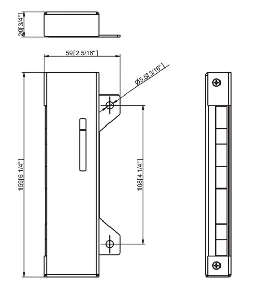
Dimensions
mm [inch]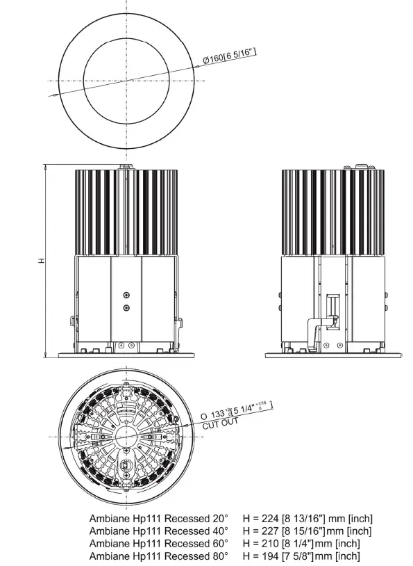
Control unit
Included items
- 1 x Ambiane HP111 Recessed US
- 1 x Control unit
- 1 x Set of cable connectors
- 1 x User manual
Optional items
- Ring Louver for Ambiane HP111 Recessed 20°
- Ambiane Power HP (P/N 10064073)
- Ambiane Power Rack US (P/N 10063873)
Photometric diagrams
Fixture set at 3200K, primary power (standard operation), 20° beam angle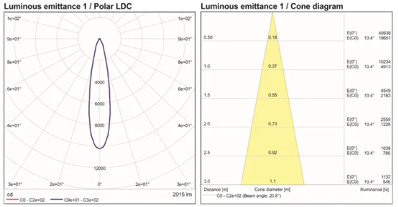
Fixture set at 3200K, secondary power (emergency operation), 20° beam angle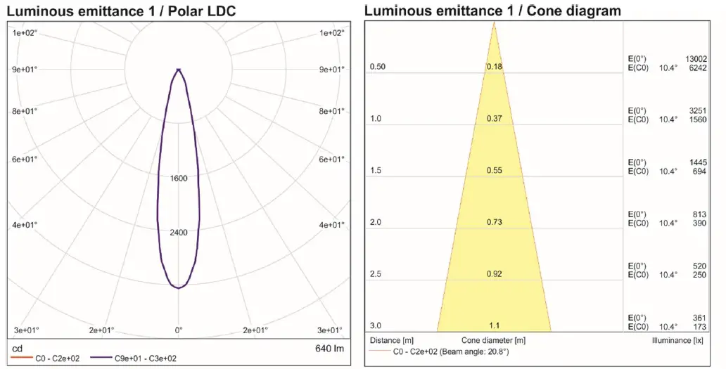
Cleaning and maintenance
Disconnect from the mains before starting any maintenance work Keep the fixture clean, especially light source and the ribbed heat sink. Maintenance and service operations are only to be carried out by a qualified person. Should you need any spare parts, please use ROBE OEM parts.
Software update
The fixture has to be connected to power during software update.
Software update by means of the Robe Uploader
The ROBE Uploader is a software for automatized software update of Robe and Anolis fixtures. It can take advantage of RDM support.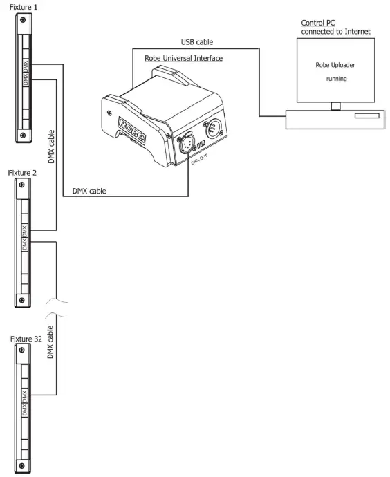
The fixtures have to be connected in a daisy-chain (max. 32 fixtures) and via the Robe Universal Interface/Robe Universal Interface WTX and a USB cable connected to the control PC with the Robe Uploader running. The fixtures have to be connected to power. The control PC should be connected to the Internet.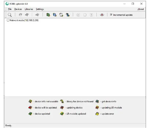
The Robe Uploader software and user manual is available at https://www.robe.cz/robe-uploader/ If you do the software update by means of the Robe Uploader, switching fixtures to the update mode (and from the update mode) is made automatically.
Note: The Robe Uploader software cannot be used if fixtures are connected by means of DALI connection.
Disposing of the product
To preserve the environment please dispose or recycle this product at the end of its life according to the local regulations and codes.
Specifications are subject to change without notice
November 22, 2021
Made in CZECH REPUBLIC by ROBE LIGHTING s.r.o. Palackeho 416/20 CZ 75701 Valasske Mezirici.


