SIEMENS GCA131.1U OpenAir GCA Spring Return Rotary Electronic Damper Actuator
OVERVIEW
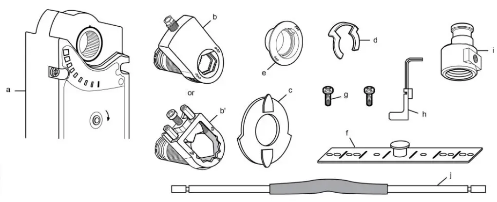
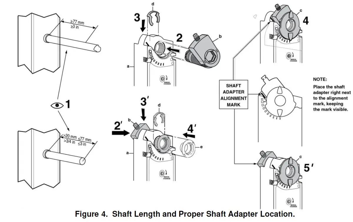
- a. Actuator
- b. Self-centering shaft adapter
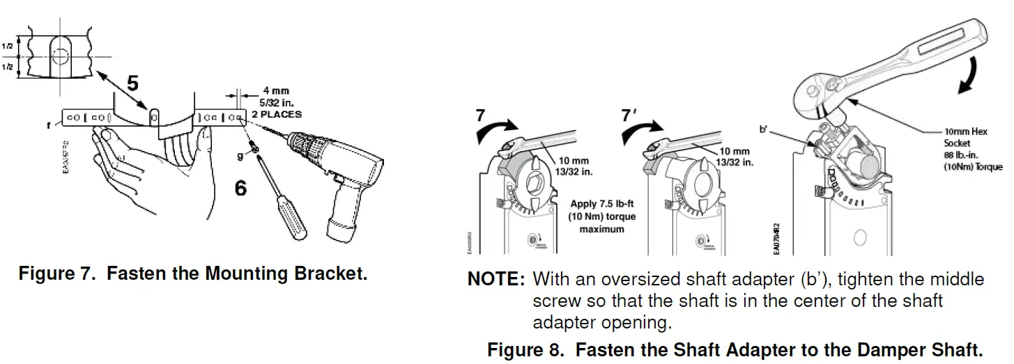
- b’. Oversized shaft adapter
- c. Position indicator
- d. Shaft adapter locking clip
- e. Position indicator adapter
- f. Mounting bracket
- g. Mounting screws
- h. 3 mm hex key
- i. Conduit adapter 1/2-inch (Not available to GCAxxx.xP models)
- j. 500 ohm resistor (GCA15x.xx only)
Product Description
Describes the steps for direct-coupled mounting of the OpenAir GCA spring return electronic damper actuators.
Product Numbers
GCAx
Warning/Caution Notations
WARNING: Personal injury or loss of life may occur if you do not follow a procedure as specified.
CAUTION: Equipment damage or loss of data may occur if you do not follow a procedure as specified.
Required Tools
- 10 mm (13/32-inch) open-end wrench
- Drill and 4 mm (5/32-in) drill bit
- 3 mm hex key (provided)
- Phillips screwdriver
- Small flat-blade screwdriver
- Marker or pencil
- Additional for oversized shaft adapter:
- 10 mm (13/32-inch) socket wrench
- 6 mm hex key
Expected Installation Time
- 30 minutes
WARNING: Do not open actuator.
CAUTION: Do not turn the 3 mm hex key against the direction of the arrow.
Mounting Positions
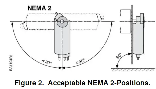
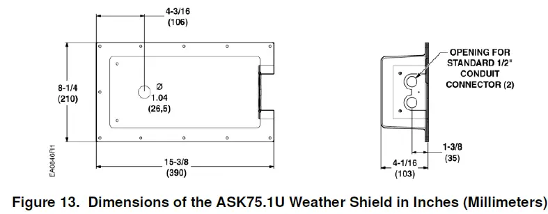
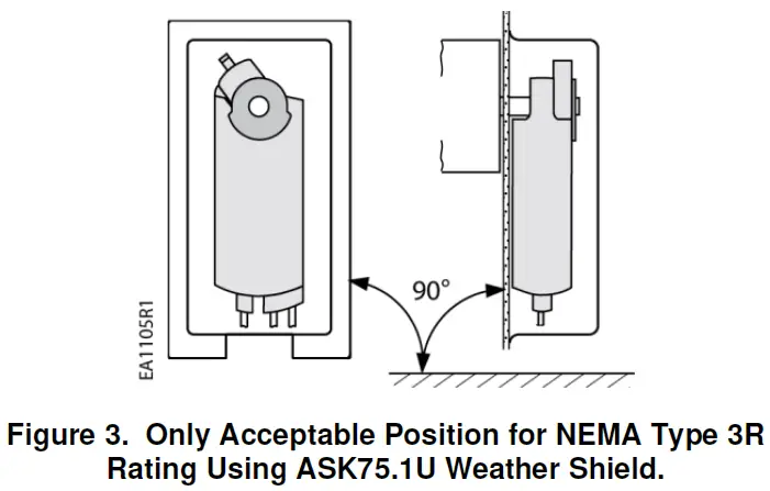 The GCA actuator is UL listed to meet NEMA Type 3R requirements (a degree of protection against rain, sleet, and damage from external ice formation) when installed with the Weather Shield (product number ASK75.1U) and outdoor-rated conduit fittings. Actuator must be in the vertical position.
Prerequisites
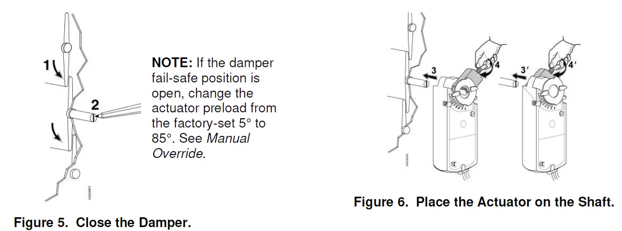
NOTE: Actuator is shipped from the factory with 5° preload. When power is applied to the actuator, the preload is released. To manually release the preload, insert the 3 mm hex key in the override opening and turn the key in the direction of the arrow.
Installation
Manual Override
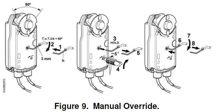
- Insert the 3 mm hex key in the override opening, (Step 1).
- Turn the key in the direction of the arrow until you reach the desired degree of opening, (Step 2).
- Hold the key in place, (Step 3).
- Insert a small flat-blade screwdriver into the gear train lock pin. Turn the screwdriver in the same direction as the arrow until you hear a click or meet slight resistance, (Step 4).
- Remove the key or keep it in place, (Step 5).
To release manual override or preload
- Insert the 3 mm hex key in the override opening, (Step 6).
- Turn the key only a short distance in the direction of the arrow, (Step 7).
- Remove the key, (Step 8). The actuator will return to 0 (fail-safe) position.
NOTE: Applying power and sending a control signal will release manual override.
Mechanical Range Adjustment
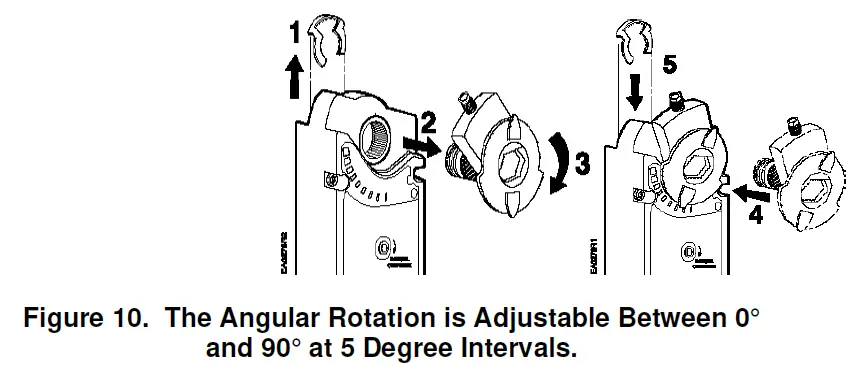
Ensure that the actuator is in the 0 (fail-safe) position when making this adjustment. If making the adjustment before the actuator is in service, take into account the factory set 5° preload. To release the preload, see To Release Manual Override or Preload section.
Other settings
For adjustment of auxiliary switches and span/offset options see the Technical Instructions listed under References.
Tandem Operation
Two GCA Actuators with 2-position or floating control signal are mounted to the same side of the damper shaft using the ASK73.1 Tandem Mounting Bracket as shown in Figure 11. Two GCA Actuators with a modulating control signal are mounted to the same side of the damper shaft using the ASK73.2U Tandem Mounting Bracket also as shown in Figure 11.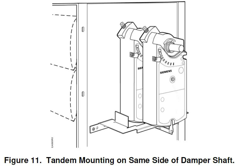
NOTE: For applications requiring single damper shaft operation by up to four GCA modulating control signal actuators mounted on each side of the damper shaft, use the GCA15x Series Actuators with Master/Slave mode operation selected. See Figure 12.
(See Wiring Diagrams for GCA15x Series master/slave operation wiring instructions.) (See OpenAir™ Spring Return Electric Damper Actuator Modulating Control Technical Instructions document 155-173P25 for complete tandem mounting instructions.)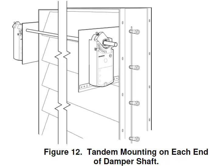
References
OpenAir™ Spring Return Electric Damper Actuator Modulating Control Technical Instructions (155-173P25). OpenAir™ Weather Shield Kits Installation Instructions (129-261).
Wiring
- All wiring must conform to NEC and local codes and regulations.
- Use earth ground isolating step-down Class 2 transformers. Do not use autotransformers.
NOTE: The maximum rating for a Class 2 step-down transformer is 100 VA. Determine the supply transformer rating by summing the VA ratings of all actuators and all other components used. It is recommended that not more than 80% of the transformer VA be utilized. The GCA actuator consumes 8 VA or less.
CAUTION: Mixed switch operation to the switching outputs of both auxiliary switches (A and B) is not permitted.
Either AC line voltage from the same phase must be applied to all six outputs of the dual auxiliary switches, or UL-Class 2 voltage must be applied to all six outputs.
NOTE: With Plenum cables, only UL-Class 2 voltage is permitted.
| Actuator | Operating Voltage | Power Consumption |
| Modulating Control | ||
| GCA16x | 24 Vac | 7 VA/5W |
| GCA15x | 24 Vac/dc | 7 VA/5W |
| 2-Position and Floating Control | ||
| GCA12x, GCA13x | 24 Vac/dc | 7 VA/5W |
| GCA22x | 120 Vac | 8 VA |
Wiring Diagrams
- Modulating 0 to 10 Vdc Control, 24 Vac: GCA16x
- Modulating 2 to 10 Vdc Control, 24 Vac/dc: GCA15x

- 2-position Control, 24 Vac/dc: GCA12x

- Floating Control, 24 Vac/dc: GCA13x

- 2-position Control, 120 Vac: GCA22x

- Special Application: Modulating 4 to 20 mA Control with GCA15x and external 500-ohm resistor

- Master/Slave: GCA15x

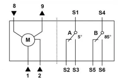
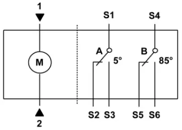
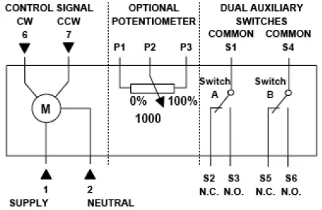
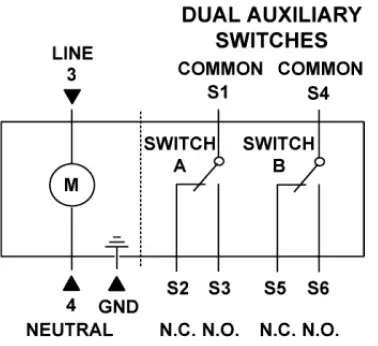
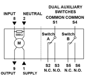
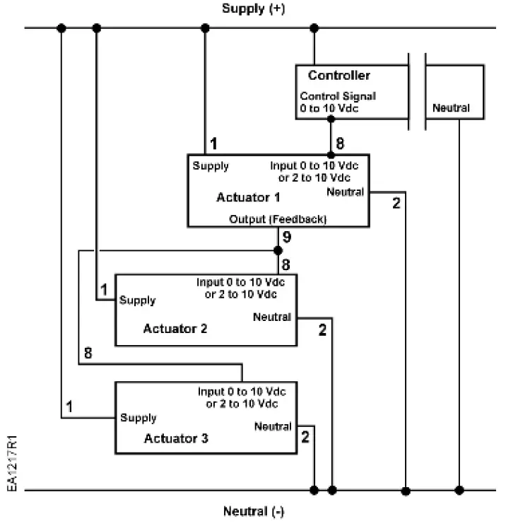
Table 2. Wire Designations
| Standard Symbol | Function | Terminal Connection | Color | |
| Standard | Plenum | |||
| 1 | Supply (SP) | G | Red | Red |
| 2 | Neutral (SN) | G0 | Black | Black |
| 3 | Line | L | Black | Black |
| 4 | Neutral | N | White | White |
| 6 | Control signal clockwise | Y1 | Violet | Violet |
| 7 | Control signal counterclockwise (GCA16x) | Y2 | Orange | Orange |
| 8 | Input Signal 0 to 10 Vdc (GCA16x)2 to 10 Vdc (GCA15x) | Y | Gray | Gray |
| 9 | Position Output 0 to 10 Vdc (GCA16x) 2 to 10 Vdc (GCA15x) | U | Pink | Pink |
| S1 | Switch A Common | Q11 | Gray/ red | Gray/ red |
| S2 | Switch A N.C. | Q12 | Gray/ blue | Gray/ blue |
| S3 | Switch A N.O. | Q14 | Gray/ pink | Gray/ pink |
| S4 | Switch B Common | Q21 | Black/ red | Black/ red |
| S5 | Switch B N.C. | Q22 | Black/ blue | Black/ blue |
| S6 | Switch B N.O. | Q24 | Black/ pink | Black/ pink |
| P1 | Feedback Potentiometer 0 to 100% P1 – P2 | a | White/ red | Black |
| P2 | Feedback Potentiometer Common | b | White/ blue | Black |
| P3 | Feedback Potentiometer 100 to 0% P3 – P2 | c | White/ pink | Black |
Retrofit Wiring
| Modulating Control (0 to 10 Vdc) Function | Siemens GCA Series | Belimo AFB Series | Honeywell MS7520 Series | Johnson M9220 Series | ||||
| Color | Number | Color | Number | Color | Number | Color | Number | |
| Supply (24V) | Red | 1 | Red | 2 | Red | 1 | Red | 2 |
| Common | Black | 2 | Black | 1 | Black | 2 | Black | 1 |
| 0(2) to 10 Vdc Input | Gray | 8 | White | 3 | White | 3 | Gray | 3 |
| 0(2) to 10 Vdc Feedback | Pink | 9 | Orange | 5 | Blue | 5 | Orange | 4 |
| 2-Position Control (24 Vac/Vdc) Function | Siemens GCA Series | Belimo AFB Series | Honeywell MS8120 Series | Johnson M9220 Series | ||||
| Color | Number | Color | Number | Color | Number | Color | Number | |
| Supply (24V) | Red | 1 | Red | 2 | Red | 1 | Red | 2 |
| Common | Black | 2 | Black | 1 | Black | 2 | Black | 1 |
| 2-Position Control (120 Vac) Function | Siemens GCA Series | Belimo AFB Series | Honeywell MS4120 Series | Johnson M9220 Series | ||||
| Color | Number | Color | Number | Terminal Only | Number | Color | Number | |
| Line (120V) | Black | 3 | Black | 2 | 1 | Black | 2 | |
| Neutral | White | 4 | White | 1 | 2 | White | 1 | |
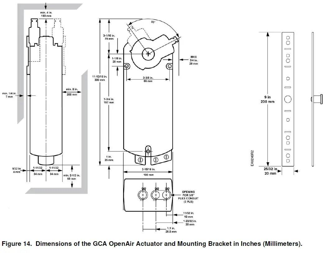
Dimensions
Information in this publication is based on current specifications. The company reserves the right to make changes in specifications and models as design improvements are introduced. OpenAir is a registered trademark of Siemens Schweiz AG. Other product or company names mentioned herein may be the trademarks of their respective owners. © 2020 Siemens Industry, Inc.
Siemens Industry, Inc.
Smart Infrastructure
1000 Deerfield Parkway
Buffalo Grove, IL 60089-4513
USA
+1-847-215-1000
Your feedback is important to us. If you have comments about this document, please send them to [email protected]
Document No. 129-404
Printed in the USA


