SIEMENS GPC166.1P Damper Actuator
Contents
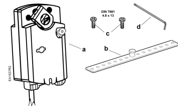
- a. Actuator
- b. Mounting bracket
- c. Mounting screws
- d. 3 mm hex key
Hints/Warnings
- Store these instructions with the actuator or with the plant documentation.
Warning
- Do not open the actuator!
- Only authorized personnel are to connect actuators.
- Do not expose the actuator’s connecting cables to water or lay the cables in water.
- The device of protection class II (protective insulation)
- The device of protection class III (protective insulation)
- For wiring and commissioning, see Technical Instructions 155-782.
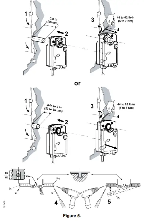
Adapter Mounting
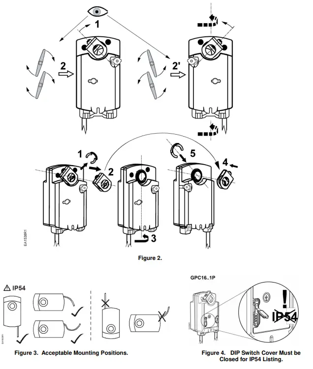
Shaft Mounting
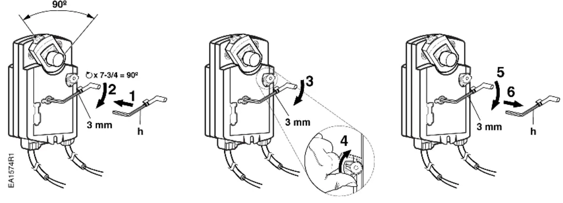
Manual Override
- winding
- positioner
- posicionar
Wiring Diagrams
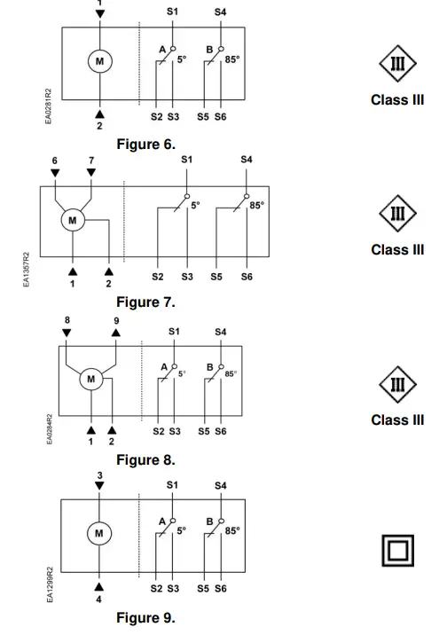
- GPC12x.1P
- 2-Position: 24 Vac/dc
- GPC13x.1P
- Floating: 24 Vac/dc
- GPC16x.1P
- Modulating: 24 Vac/dc
- GPC32x.1U
- 2-Position: 100 to 240 Vac
Auxiliary Switches
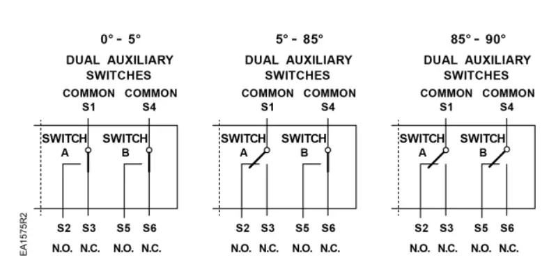
| Actuator Position | Switch A Common S1 Connected to | Switch B Common S4 Connected to |
| 0° to 5° | S3 | S6 |
| 5° to 85° | S2 | S6 |
| 85° to 90° | S2 | S5 |
CAUTION:
- Mixed switch operation to the switching outputs of both dual-end switches (5° and 85°) is not permitted.
- Either AC line voltage from the same phase must be applied to all six outputs of the fixed dual-end switches, or UL-Class 2 voltage must be applied to all six outputs.
DIP Switches
NOTE: The black position indicates the active switch setting.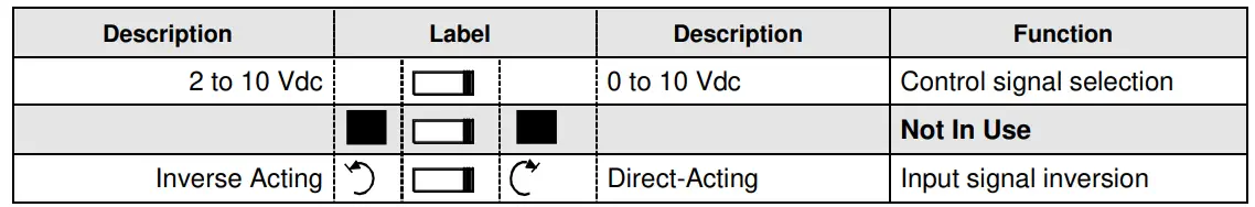
Control Signal Selection
- Selects the control and feedback signals
- Input Signal Inversion Allows inverting the control input signal
- The arrow direction indicates opening or closing (closing or opening) when operating an actuator with a given control signal.
 Direct acting (Factory setting)
- Input signal 0 Vdc ► fail-safe position
 Inverse acting
- Input signal 10 Vdc ► fail-safe position
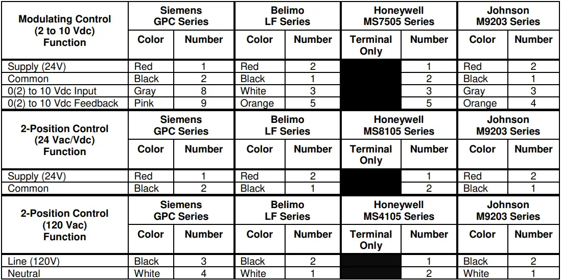
Wire Designations
Table 1.
| Connecting | Standard Symbol | Function | Color | Color Symbol |
|
24 Vac/dc Actuator | 1 | Supply (SP) | Red | RD |
| 2 | System Neutral | Black | BK | |
| 6 | Control signal clockwise | Violet | VT | |
| 7 | Control signal counterclockwise | Orange | OG | |
| 8 | Input Signal: 0 (2) to 10 Vdc or 10 to 0 (2) Vdc (GPC16x) | Gray | GY | |
| 9 | Position Output: 0 (2) to 10 Vdc or 10 to 0 (2) Vdc (GPC16x) | Pink | PK | |
| 120 Vac | 3 | Supply | Black | BK |
| 4 | Neutral | White | WH | |
|
Auxiliary Switches | 1 | Switch A – Common | S1 | Gray/red |
| 2 | Switch A – N.O. | S2 | Gray/blue | |
| 3 | Switch A – N.C. | S3 | Gray/pink | |
| 4 | Switch B – Common | S4 | Black/red | |
| 5 | Switch B – N.O. | S5 | Black/blue | |
| 6 | Switch B – N.C. | S6 | Black/pink |
Retrofit Wiring
Dimensions
in Inches (mm)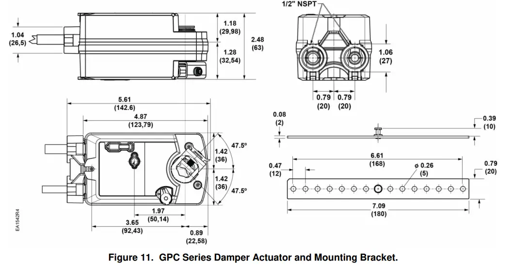
Information in this publication is based on current specifications.
The company reserves the right to make changes in specifications and models as design improvements are introduced.
OpenAir is a registered trademark of Siemens Schweiz, AG.
Other product or company names mentioned herein may be the trademarks of their respective owners.
- © 2019 Siemens Industry, Inc.
- Siemens Industry, Inc.
- Building Technologies Division
- 1000 Deerfield Parkway
- Buffalo Grove, IL 60089-4513
- USA
- Tel. +1-847-215-1000
- Your feedback is important to us.
- If you have comments about this document, please send them to sbt_[email protected]
- Document No. 129-585
- Printed in the USA


