
SIEMENS GIB164.1P NSR Rotary Electronic Damper Actuators
Product Description
The steps for direct-coupled mounting of the OpenAir GBB/GIB series non-spring return (NSR) three-position or modulating control rotary electronic damper actuator.
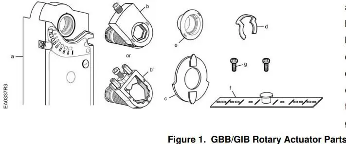
- a. Actuator
- b. Self-centering shaft adapter
- b’. Oversized shaft adapter
- c. Position indicator
- d. Shaft adapter locking clip
- e. Position indicator adapter
- f. Mounting bracket
- g. Mounting screws
Product Numbers
GBB/GIB13x
GBB/GIB16x
Warning/Caution Notations
- WARNING:
Personal injury or loss of life may occur if you do not follow the procedures as specified. - CAUTION:
Equipment damage or loss of data may occur if you do not follow procedure as specified.
Required Tools
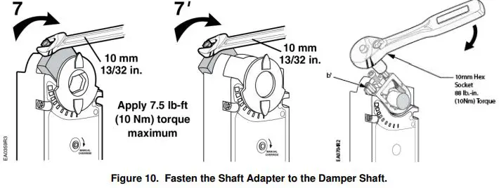
- 10 mm (13/32-inch) open-end wrench
- 6 mm (1/4-inch) open-end wrench for oversized shaft adapter
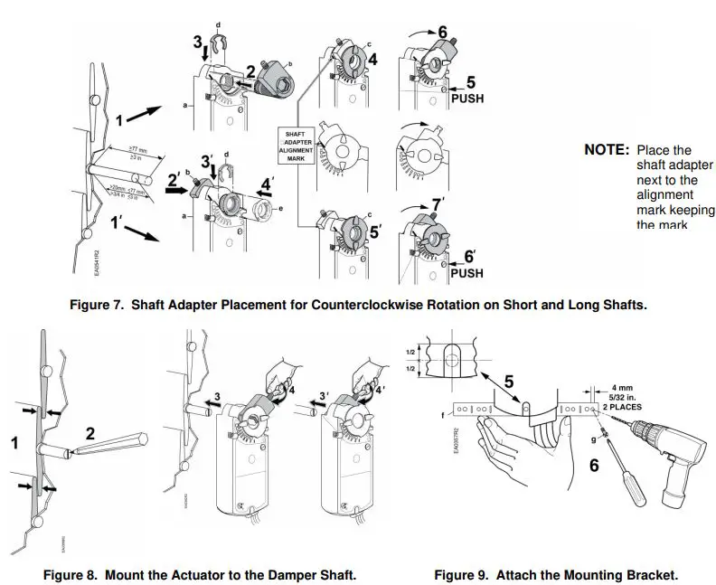
- Drill and 4 mm (5/32-inch) drill bit
- Phillips screwdriver
- Marker or pencil
- Adjustable pliers
Additional for oversized shaft adapter: - 10 mm (13/32-inch) socket wrench
- 6 mm hex key
Estimated Installation Time
30 minutes
Mounting Positions
Item Number 129-417, Rev. DA
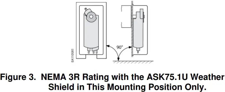
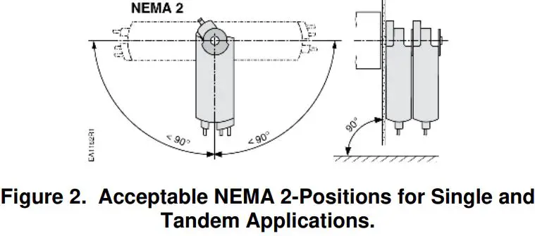
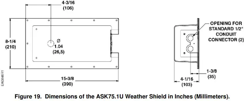
The GBB/GIB actuator is UL listed to meet NEMA 3R requirements (a degree of protection against rain, sleet, and damage from external ice formation) when installed with the weather shield, product number ASK75.1U and outdoor-rated conduit fittings. The GBB/GIB must be in the vertical position.
Prerequisite
The actuator is shipped from the factory with a 5° pre-load to ensure tight close-off of the damper. To release the pre-load, press the PUSH button before mounting the actuator.
Installation
WARNING:
Do not open the actuator.
- Place the actuator on the damper shaft with the front of the actuator accessible. The label and the manual override button are on the front side.
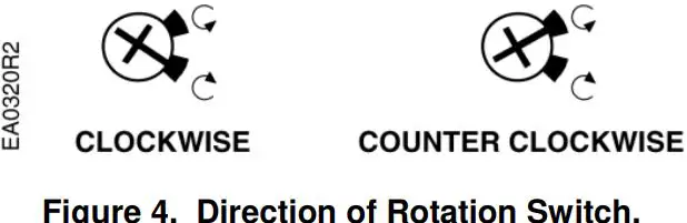
- For the 16x series only: Determine the rotation of the damper shaft. Set the direction of rotation arrow to match the rotation.

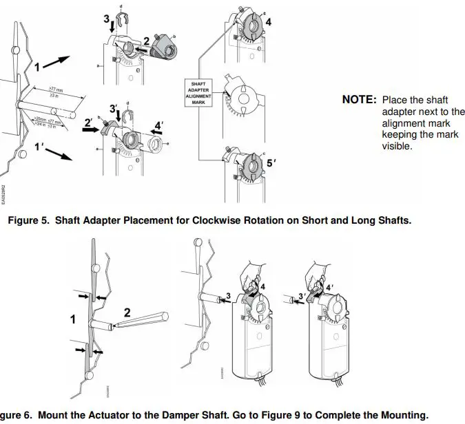
Document No. 129-417 Installation Instructions April 1, 2020 - For all models: See Figure 5 and Figure 6 for clockwise-to-open (CW) installation. See Figure 7 and Figure 8 for counterclockwise-to-open (CCW) installation.
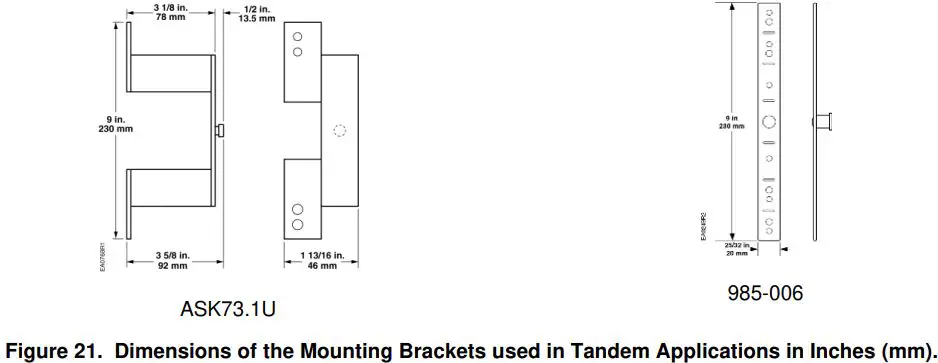
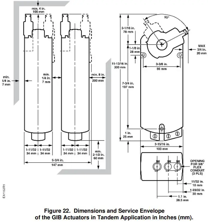
For Tandem Applications
- The direction of rotation switches must be set identically on both actuators according to the clockwise or counterclockwise rotation of the damper shaft. The factory setting is clockwise.
- Minimum damper drive shaft length is 4 inches (100 mm).

CAUTION:
No more than three actuators are to be used in tandem applications.
NOTE:
GIB163 and GIB164 models containing offset and span features can not be used in a tandem application.
NOTE: With an oversized shaft adapter (b’), tighten the middle screw so that the shaft is in the center of the shaft adapter opening.
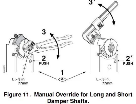
Manual Override
To move the damper blades without power present, do the following:
- Hold down the PUSH button.
- Make adjustments to the damper position.
- Release the PUSH button.
NOTE: If there is no load, the actuator will hold the new damper position. If load conditions exist, the actuator might not be able to hold.
Once power is restored, the actuator returns to automated control.
Mechanical Range Adjustment
The angular rotation is adjustable between 0° and 90° at 5-degree intervals.
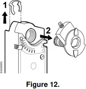
- Loosen the shaft adapter from the damper shaft and remove the actuator from the damper shaft.
- Remove the clip and shaft adapter from the actuator. See Figure 12.

- Return the actuator gear train to the “0” position using the steps which follow for the clockwise or counterclockwise damper shaft rotation.
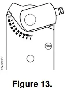
Clockwise-to-open:
a. Insert the shaft adapter to the right as close as possible to the raised stop. Figure 13.
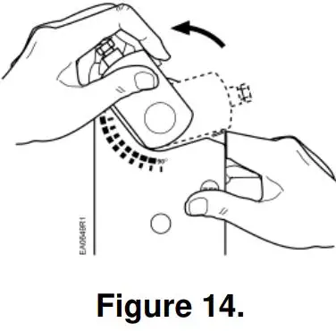
b. Hold down the PUSH button and rotate the shaft adapter to the left until it stops. Figure 14. c. Release the PUSH button.
d. If the shaft adapter is not resting against the left raised stop, remove the adapter and insert it against the left stop.
e. Place the position indicator to the “0” position on the outside scale. Figure 15.Counterclockwise-to-open:
a. Insert the shaft adapter to the left as close as possible to the raised stop.
b. Hold down the PUSH button and rotate the shaft adapter to the right until it stops.
c. Release the PUSH button.
d. If the shaft adapter is not resting against the right raised stop, remove the adapter and insert it against the right stop.
e. Place the position indicator to “0” on the inside scale.
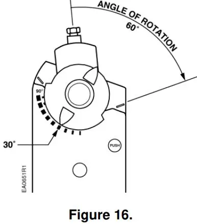
- Determine the angle of rotation for the damper blade shaft. Subtract that amount from 90°.
- Remove the shaft adapter and insert it with the position indicator pointing to mark on the scale calculated in the previous step. Figure 16.

- Attach the clip.
- Rotate the damper blade shaft to its 0 position.
- Return the actuator to the damper shaft and tighten the shaft adapter to the damper shaft.
 c. Release the PUSH button.
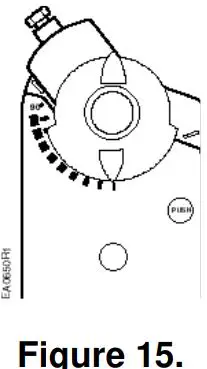
Other settings
For adjustment of auxiliary switches and span/offset options, see Technical Instructions (GBB/GIB16x 155-176P25; GBB/GIB13x 155-177P25).
Wiring
- All wiring must conform to NEC and local codes and regulations.
- Use earth ground isolating step-down Class 2 transformers. Do not use auto transformers.
- The maximum rating for a Class 2 step-down transformer is 100 VA. Determine the supply transformer rating by summing the total VA of all actuators and components used. It is recommended that no more than 10 actuators are powered by one transformer.
WARNING:
Do not parallel wire GBB/GIB actuators with any other type of actuator, including GBB/GIB actuators with date codes earlier than 501.
WARNING:
It is recommended to switch off the power during two-position control when the actuator has reached the open or closed position to enhance life span and reduce power consumption.
WARNING:
Mixed switch operation is not permitted to the switching outputs of both auxiliary switches (A and B).
Either AC line voltage from the same phase must be applied to all six outputs of the dual auxiliary switches, or UL-Class 2 voltage must be applied to all six outputs.
NOTE: With plenum cables, only UL-Class 2 voltage is permitted.

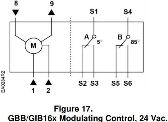
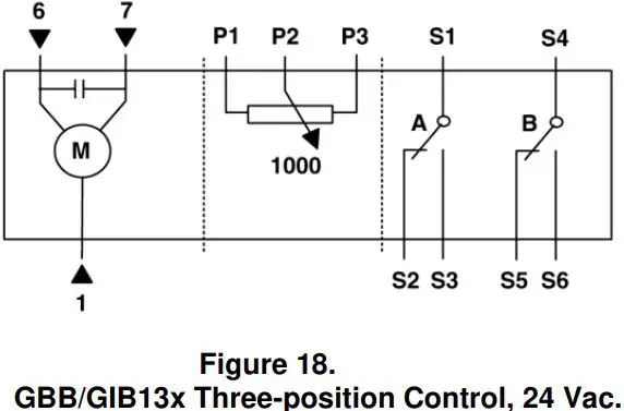
Table 1
| Standard Symbol | Function | Terminal Designations | Color |
| 1 | Supply (SP) | G | Red |
| 2 | Neutral (SN) | G0 | Black |
| 6 | Control signal clockwise | Y1 | Violet |
| 7 | Control signal counterclockwise | Y2 | Orange |
| 8 | 0 to 10 Vdc input signal | Y | Gray |
| 9 | Output for 0 to 10 Vdc position indication | U | Pink |
| P1 | Feedback potentiometer 0 to 100% P1 – P2 | a | White/red |
| P2 | Feedback potentiometer Common | b | White/blue |
| P3 | Feedback potentiometer 100 to 0% P3 – P2 | c | White/pink |
| S1 | Switch A Common | Q11 | Gray/red |
| S2 | Switch A N.C. | Q12 | Gray/blue |
| S3 | Switch A N.O. | Q14 | Gray/pink |
| S4 | Switch B Common | Q21 | Black/red |
| S5 | Switch B N.C. | Q22 | Black/blue |
| S6 | Switch B N.O. | Q24 | Black/pink |
Retrofit Wiring
| Modulating Control (0 to 10 Vdc) | Siemens GBB Series GIB Series | Belimo AMB Series GMB Series | Honeywell MN7220 Series MN7220 Series | Johnson M9124 Series M9132 Series | ||||
| Function | Color | Number | Color | Number | Terminal Only | Number | Terminal Only | Number |
| Supply 24V | Red | 1 | Red | 2 | 1 | 2 | ||
| Common | Black | 2 | Black | 1 | 2 | 1 | ||
| 0(2) to 10 Vdc Input | Gray | 8 | White | 3 | 3 | 3 | ||
| 0(2) to 10 Vdc Feedback | Pink | 9 | Orange | 5 | 5 | 4 | ||
| Floating Control | Siemens GBB Series GIB Series | Belimo AMB Series GMB Series | Honeywell MN6120 Series MN6134 Series | Johnson M9124 Series M9132 Series | ||||
| Function | Color | Number | Color | Number | Terminal Only | Number | Terminal Only | Number |
| Common | Red | 1 | Black | 1 | 2 | 1 | ||
| 24V CW | Violet | 6 | Red | 2 | 3 | 2 | ||
| 24V CCW | Orange | 7 | White | 3 | 4 | 3 | ||
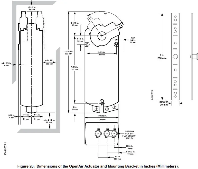
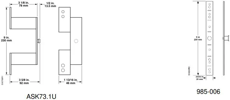
Dimensions
Information in this publication is based on current specifications. The company reserves the right to make changes in specifications and models as design improvements are introduced. OpenAir is a registered trademark of Siemens Schweiz, AG. Other product or company names mentioned herein may be the trademarks of their respective owners. © 2020 Siemens Industry, Inc.
Siemens Industry, Inc. Smart Infrastructure 1000 Deerfield Parkway Buffalo Grove, IL 60089 + 1 847-215-1000
Your feedback is important to us. If you have comments about this document, please send them to [email protected]
Document No. 129-417 Printed in the USA


