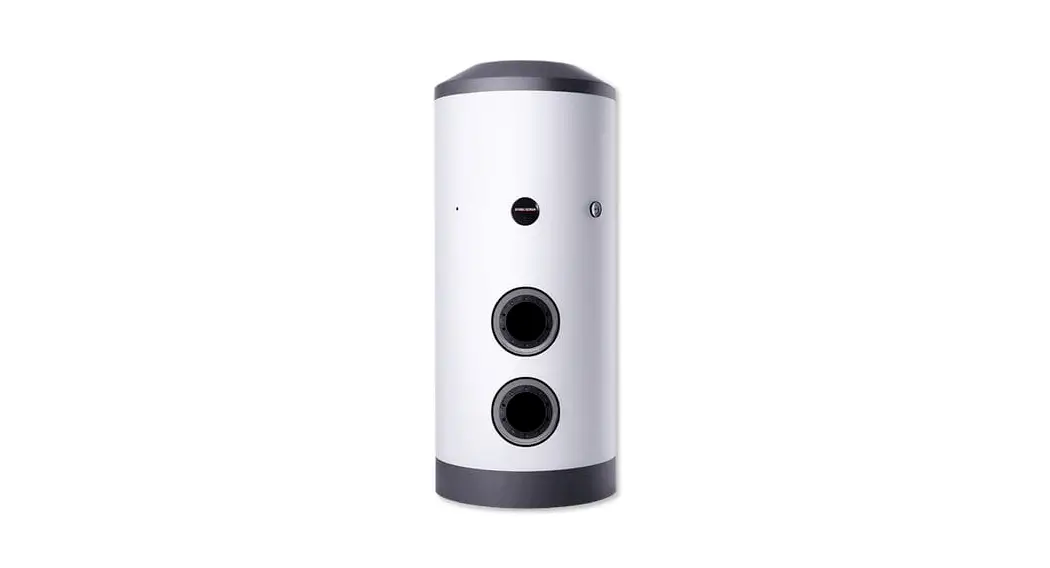
![]() SB-VS Series Solar DHW Cylinders
SB-VS Series Solar DHW Cylinders
Installation Guide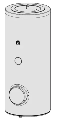 » SB-VTS 200/3, » SB-VTS 300/3 ,» SB-VTS 400/3 ,» SB-VTS 500/3
OPERATION AND INSTALLATION
Solar DHW cylinders
OPERATION
1. General information
The chapter “Operation” is intended for appliance users and qualified contractors.
The chapter “Installation” is intended for qualified contractors.
Note
Read these instructions carefully before using the appliance and retain them for future reference. Pass on the instructions to a new user if required.
1.1 Safety instructions
1.1.1 Structure of safety instructions!
KEYWORD Type of risk
Here, possible consequences are listed that may result from failure to observe the safety instructions. ff Steps to prevent the risk are listed.
1.1.2 Symbols, type of risk
| Symbol | Type of risk |
 | Injury |
| Electrocution | |
| Burns (burns, scalding) |
1.1.3 Keywords
| KEYWORD | Meaning |
| DANGER | Failure to observe this information will result in serious injury or death. |
| WARNING | Failure to observe this information may result in serious injury or death. |
| CAUTION | Failure to observe this information may result in non-serious or minor injury. |
1.2 Other symbols in this documentation
Note
General information is identified by the adjacent symbol.
Read these texts carefully.
| Symbol | Meaning |
| Material losses (appliance damage, consequential losses and environmental pollution) | |
 | Appliance disposal |
This symbol indicates that you have to do something. The action you need to take is described step by step.
1.3 Units of measurement![]() Note
Note
All measurements are given in mm unless stated otherwise.
Safety
2.1 Intended use
The appliance is intended for domestic use. It can be used safely by untrained persons. The appliance can also be used in non-domestic environments, e.g. in small businesses, as long as it is used in the same way.
The appliance is intended for heating domestic hot water in conjunction with solar collectors and optionally with further heat sources for reheating the upper half of the cylinder.
Any other use beyond that described shall be deemed inappropriate. Observation of these instructions and of the instructions for any accessories used is also part of the correct use of this appliance.
2.2 Safety instructions![]() WARNING Burns
WARNING Burns
There is a risk of scalding at outlet temperatures in excess of 43 °C.
WARNING Injury
The appliance may be used by children aged 8 and up and persons with reduced physical, sensory or mental capabilities or a lack of experience and know-how, provided that they are supervised or they have been instructed on how to use the appliance safely and have understood the resulting risks. Children must never play with the appliance. Children must never clean the appliance or perform user maintenance unless they are supervised.
Material losses
The appliance is pressurized. During the heat-up process, expansion water will drip from the safety valve. If water continues to drip when heating is completed, please inform your qualified contractor.
Appliance description
The DHW is heated via two smooth tube internal indirect coils. In addition, a threaded immersion heater and a flanged immersion heater can be connected. You can use the appliance to supply one or more draw-off points. The appliance is equipped with an inspection flange and thermometer. The steel cylinder is coated on the inside with special directly applied “antic or ® ” enamel and equipped with a protective anode. This anode protects the inside of the cylinder from corrosion. The cylinder is surrounded by foam insulation and a painted sheet metal casing.
Cleaning, care, and maintenance
- Have the function of the safety assembly and electrical safety of the fitted accessories regularly checked by a qualified contractor.
- Have the protective anode checked by a qualified contractor after the first two years of use? The qualified contractor will then determine the intervals at which repeat checks should be performed.
- Never use abrasive or corrosive cleaning agents. A damp cloth is sufficient for cleaning the appliance.
4.1 Scaling
Almost every type of water will deposit limescale at high temperatures. This settles inside the appliance and affects both performance and service life. If a threaded immersion heater is installed, the heating elements must be descaled from time to time. A qualified contractor who knows the local water quality will tell you when the next service is due.
- Check the taps regularly. Limescale deposits at the tap outlets can be removed using commercially available descaling agents.
Troubleshooting
| Problem | Cause | Remedy |
| The flow rate is low. | The aerator in the tap or the shower head is scaled up or dirty. | Clean and/or descale the aerator or shower head. |
If you cannot remedy the fault, notify your qualified contractor.
To facilitate and speed up your inquiry, please provide the serial number from the type plate (no. 000000-0000-000000):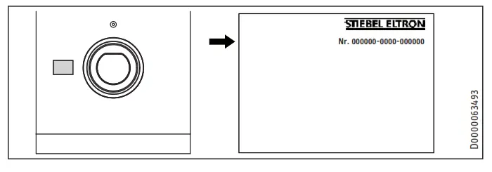
Safety
Only a qualified contractor should carry out the installation, commissioning, maintenance, and repair of the appliance.
6.1 General safety instructions
We can only guarantee trouble-free function and operational reliability if original spare parts intended for the appliance are used.
6.2 Instructions, standards, and regulations
![]() Note
Note
Observe all applicable national and regional regulations and instructions.
7.1 Required accessories
Depending on the static pressure, safety assemblies and pressure-reducing valves are available. These type-tested safety assemblies protect the appliance against unacceptable excess pressure.
7.2 Additional accessories
Threaded immersion heaters and indirect coils are available as accessories. If it is not possible to insert a rod anode from above, install a segmented anode.
Preparation
8.1 Installation site
Always install the appliance in a room free from the risk of frost and near the draw-off point.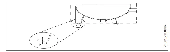
- Ensure the floor is level. Use the adjustable feet to compensate for any unevenness in the floor.
- Ensure the floor has a sufficient load-bearing capacity (see chapter “Specification / Data table”).
- Observe the room height and height when tilted (see chapter “Specification / Data table”).
Minimum clearances
The minimum side clearances can be swapped between left and right.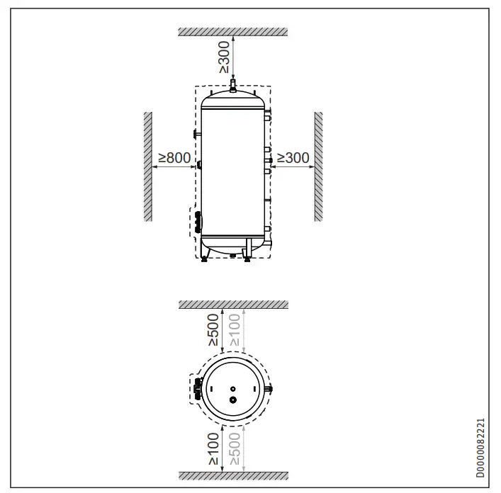
Maintain the minimum clearances.
8.2 Transport
For transportation, the appliance is secured to the pallet with metal brackets.
- Remove the screws from the pallet.
- Turn the metal brackets to the inside of the adjustable feet under the appliance.
Installation
9.1 Heat exchanger connection
Flush the indirect coils with water before the connection.
9.1.1 Water quality, solar circuit
A glycol/water mixture of up to 60 % is permitted for the indirect coil in the solar circuit, provided only dezincification-resistant metals, glycol-resistant gaskets, and diaphragm expansion vessels suitable for glycol are used throughout the system.
9.1.2 Oxygen diffusion![]() Material losses
Material losses
Avoid open-vented solar thermal systems and plastic pipes which are permeable to oxygen.
With plastic pipes that are permeable to oxygen, oxygen diffusion can cause corrosion on the steel components of the solar thermal system (e.g. on the indirect coil of the DHW cylinder).
9.2 Installing the immersion heater (accessory) if required
HP-SB 2/040 threaded immersion heater
Prepare the connector for the threaded immersion heater: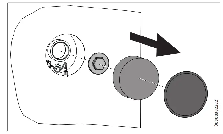
Install the threaded immersion heater:
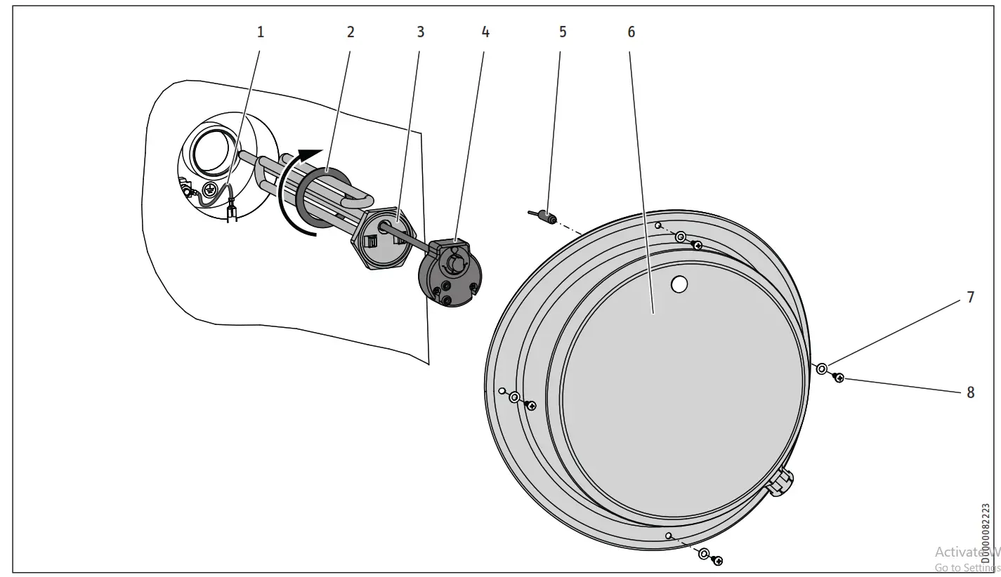
- Sheet metal casing earth
- Gasket
- Heating element
- Temperature selector
- Control indicator
- Flange cover
- Washer
- Screw
HP-SB 3/150 flanged immersion heater
Remove the blank flange: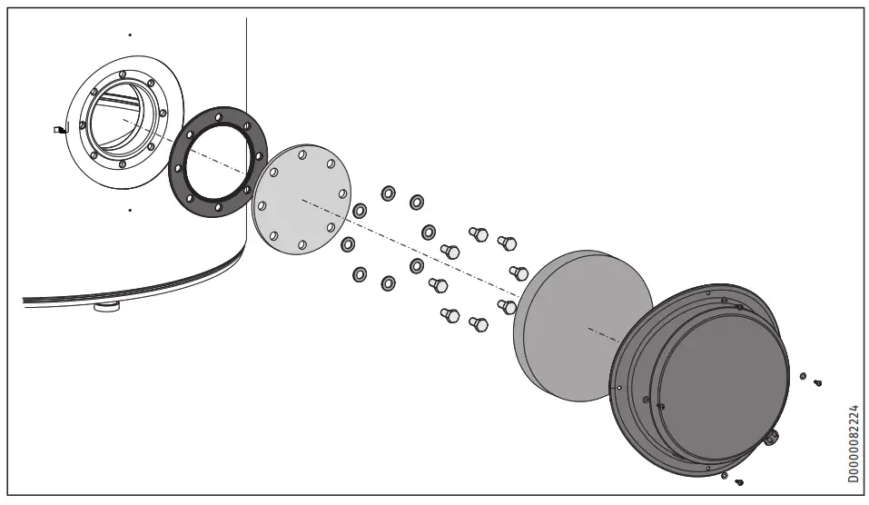
Install the flanged immersion heater: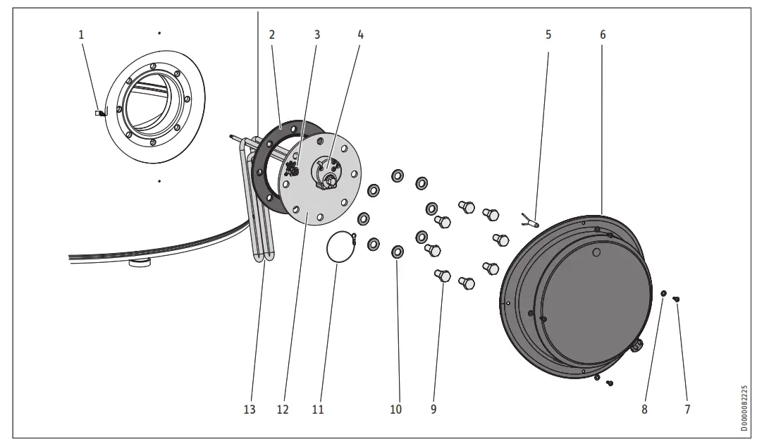
- Sheet metal casing earth
- Flange gasket
- Flange earth screw
- Temperature selector
- Control indicator
- Flange cover
- Screw 4.2×16
- Washer 4.3
- M12x25 screw
- Washer 13
- Earth cable
- Flange D = 180×5
- Heating element
Electrical connection
 WARNING Electrocution
Carry out all electrical connection and installation work in accordance with relevant regulations.WARNING Electrocution
The connection to the power supply must be in the form of a permanent connection. Ensure the appliance can be separated from the power supply by an isolator that disconnects all poles with at least 3 mm contact separation.
![]() Material losses
Material losses
Observe the type plate. The specified voltage must match the mains voltage.
![]() Note
Note
Ensure that the appliance is earthed.
- Feed the connecting cable into the control panel interior.
- Connect the load (see chapter “Specification / Wiring diagrams and connections”).
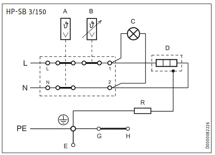
- Thermal fuse
- Temperature selector
- Control indicator
- Heating element
- Sheet steel casing
- Cylinder
- Rod anode
- Electrical resistance 560 Ω
Flange earth screw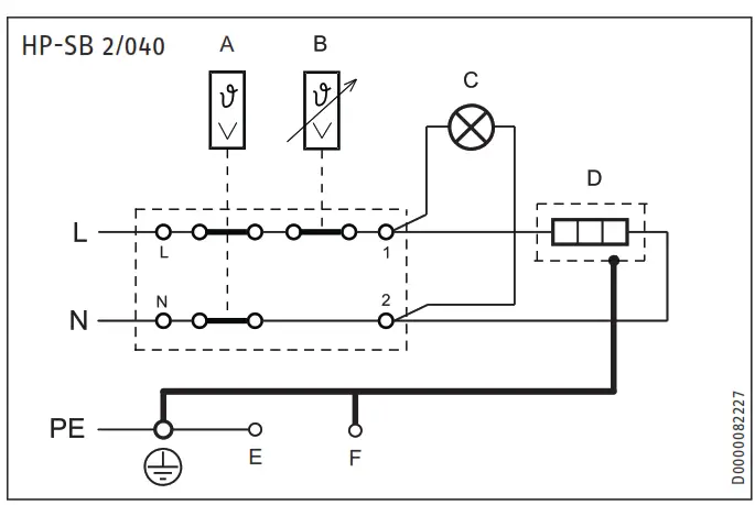
A Thermal fuse
B Temperature selector
C Control indicator
D Heating element
E Sheet steel casing
F Rod anode
Flange earth screw
9.3 Water connection and safety assembly
9.3.1 Safety instructions
![]() Note
Note
Carry out all water connection and installation work in accordance with regulations.
![]() Note
Note
Connect the hydraulic connections with flat gaskets.
Cold water line
Steel or copper pipes, or plastic pipework, are approved materials.
![]() Material losses
Material losses
A safety valve is required.
DHW line
Copper or plastic are approved materials for pipework.
![]() Material losses
Material losses
For the combined use of a threaded immersion heater and plastic pipework systems, observe the maximum permissible temperature and the maximum permissible pressure specified in the chapter “Specification / Data table”.
![]() Material losses
Material losses
Operate the appliance only with pressure-tested taps.
Commissioning
9.3.2 Connection
- Flush the pipework thoroughly.
- Observe the information in the installation instructions of safety assembly.
- Connect the DHW outlet and the cold water inlet lines with the safety assembly. Please note that, depending on the static pressure, you may also need a pressure-reducing valve.
- Size the drain so that water can drain off unimpeded when the safety valve is fully opened. The safety valve discharge aperture must remain open to the atmosphere.
- Install the discharge pipe of the safety assembly with a constant slope.
9.4 Solar and heating circuit sensors
- Fit the sensors for the control units used according to the relevant installation instructions (for sensor wells, see chapter “Specification / Dimensions and connections”).
- Route the connecting lead to the solar or heating circuit control unit.
10.4.1 If using a flanged immersion heater
![]() Material losses
Material losses
Boiling dry destroys the high-limit safety cut-out of the flanged immersion heater and the controller-limiter combination must then be replaced.
![]() Material losses
Material losses
If an indirect coil is installed in the same cylinder, its maximum temperature must be limited. This prevents the temperature limiter of the threaded immersion heater from responding.
- Fill the system with water.
- Turn the temperature selector to the maximum.
- Switch the power supply ON.
- Check the appliance function.
- Check the function of the safety assembly.
10.1 Initial start-up
- Open a downstream draw-off point until the appliance is full and the pipes are free of air.
- Vent the internal indirect coil.
- Check the solar thermal system for correct function.
- Fit the accessories and check them if necessary.
- Check the safety valve for correct function.
- Check that the DHW temperature displayed on the heat pump control unit is correct.
10.1.1 Appliance handover
- Explain the appliance function to users and familiarise them with how it works.
- Make the user aware of potential dangers, especially the risk of scalding.
- Hand over these instructions.
10.2 Recommissioning
See chapter “Initial start-up”.
Appliance shutdown
- If necessary, disconnect any accessories installed from the mains at the MCB/fuse in the fuse box.
- Drain the appliance. See chapter “Maintenance / Draining the appliance”.
Troubleshooting
| Fault | Cause | Remedy |
| The safety valve drips when the heating is switched off. | The valve seat is contaminated. | Clean the valve seat. |
Maintenance
![]() WARNING Electrocution
WARNING Electrocution
Carry out all electrical connection and installation work in accordance with relevant regulations.
If you need to drain the appliance, observe the chapter “Draining the appliance”.
13.1 Checking the safety valve
ff Regularly vent the safety valve on the safety assembly until a full water jet is discharged.
13.2 Checking / replacing the protective anode
- Check the protective anode after the first 2 years of use and replace if necessary. For this, observe the maximum transition resistance of 0.3 Ω between the protective anode and the cylinder.
- Afterward, determine the time intervals at which further checks should be carried out.
13.3 Draining the appliance![]() WARNING Burns
WARNING Burns
Hot water may escape during draining.
- Close the shut-off valve in the cold water supply line.
- Open the hot water taps on all draw-off points.
- Drain the appliance via the drain valve.
13.4 Cleaning and descaling the appliance
For the torque of the flange screws, see chapter “Specification / Dimensions and connections”.
- Never use descaling pumps.
- Never treat the cylinder surface or the protective anode with descaling agents.
Specification
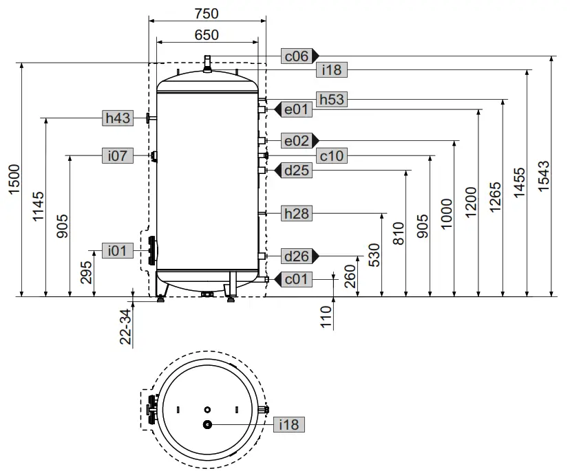
14.1 Dimensions and connections
SB-VTS 200/3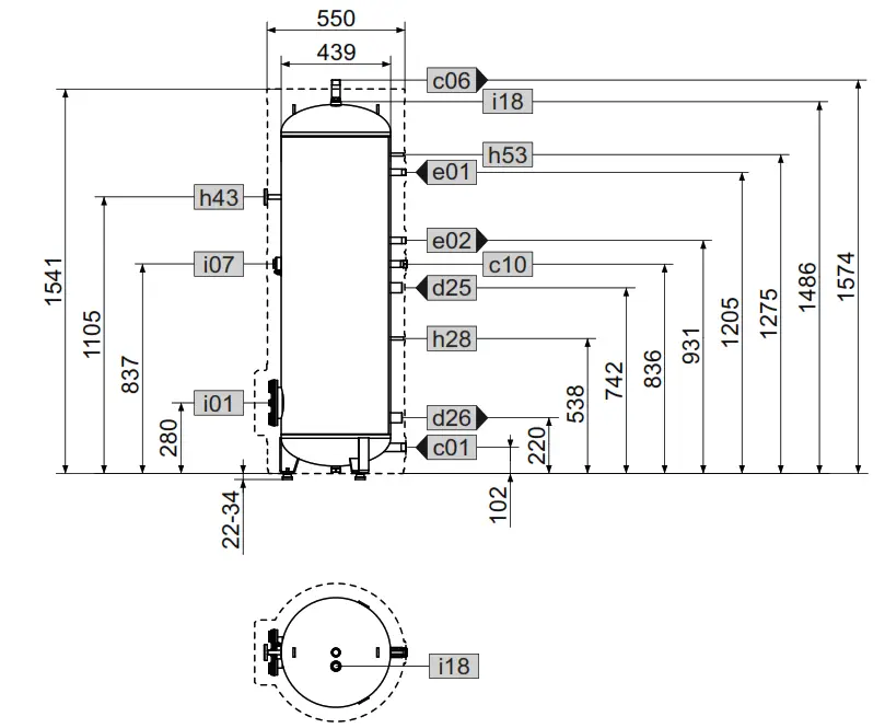
| c01 | Cold water inlet |
| c06 | DHW outlet |
| c10 | DHW circulation |
| d25 | Solar flow |
| d26 | Solar return |
| e01 | Heating flow |
| e02 | Heating return |
| h28 | Sensor solar cylinder |
| h43 | Thermometer |
| h53 | Sensor heating |
| i01 | Flange |
| i07 | Electric emergency/booster heater |
| i18 | Protective anode |
| SB-VTS 200/3 | ||
| Male thread | G 1 | |
| Male thread | G 1 | |
| Male thread | G 3/4 | |
| Male thread | G 1 | |
| Male thread | G 1 | |
| Male thread | G 1 | |
| Male thread | G 1 | |
| Diameter | mm | 9.5 |
| Diameter | mm | 9.5 |
| Diameter | mm | 9.5 |
| Diameter | mm | 180 |
| Pitch circle diameter | mm | 150 |
| Screws | M 12 | |
| Torque | Nm | 25 |
| Female thread | G 1 1/4 | |
| Female thread | G 1 1/4 | |
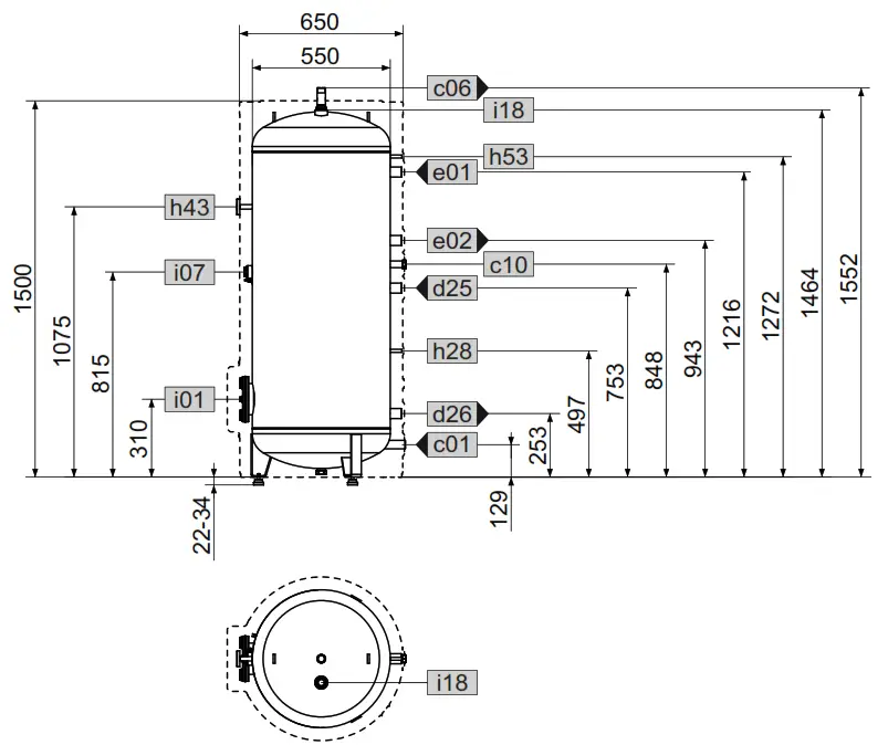
| c01 | Cold water inlet |
| c06 | DHW outlet |
| c10 | DHW circulation |
| d25 | Solar flow |
| d26 | Solar return |
| e01 | Heating flow |
| e02 | Heating return |
| h28 | Sensor solar cylinder |
| h43 | Thermometer |
| h53 | Sensor heating |
| i01 | Flange |
| i07 | Electric emergency/booster heater |
| i18 | Protective anode |
| SB-VTS 300/3 | ||
| Male thread | G 1 | |
| Male thread | G 1 | |
| Male thread | G 3/4 | |
| Male thread | G 1 | |
| Male thread | G 1 | |
| Male thread | G 1 | |
| Male thread | G 1 | |
| Diameter | mm | 9.5 |
| Diameter | mm | 9.5 |
| Diameter | mm | 9.5 |
| Diameter | mm | 180 |
| Pitch circle diameter | mm | 150 |
| Screws | M 12 | |
| Torque | Nm | 25 |
| Female thread | G 1 1/4 | |
| Female thread | G 1 1/4 | |
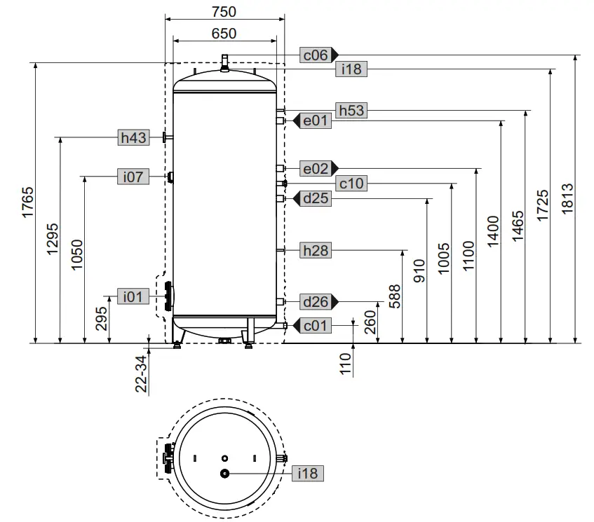
| c01 | Cold water inlet |
| c06 | DHW outlet |
| c10 | DHW circulation |
| d25 | Solar flow |
| d26 | Solar return |
| e01 | Heating flow |
| e02 | Heating return |
| h28 | Sensor solar cylinder |
| h43 | Thermometer |
| h53 | Sensor heating |
| i01 | Flange |
| i07 | Electric emergency/booster heater |
| i18 | Protective anode |
| SB-VTS 300/3 | ||
| Male thread | G 1 | |
| Male thread | G 1 | |
| Male thread | G 3/4 | |
| Male thread | G 1 | |
| Male thread | G 1 | |
| Male thread | G 1 | |
| Male thread | G 1 | |
| Diameter | mm | 9.5 |
| Diameter | mm | 9.5 |
| Diameter | mm | 9.5 |
| Diameter | mm | 180 |
| Pitch circle diameter | mm | 150 |
| Screws | M 12 | |
| Torque | Nm | 25 |
| Female thread | G 1 1/4 | |
| Female thread | G 1 1/4 | |
Sectional view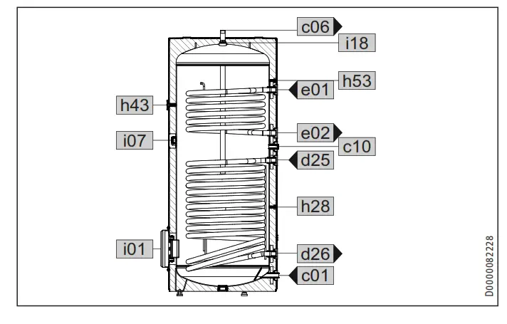
14.2 Energy consumption data
Product datasheet: DHW cylinder to Regulation (EU) No 812/2013
| SB-VTS 200/3 | SB-VTS 300/3 | SB-VTS 400/3 | SB-VTS 500/3 | ||
| 200162 | 200163 | 200164 | 200165 | ||
| Manufacturer | STIEBEL ELTRON | STIEBEL ELTRON | STIEBEL ELTRON | STIEBEL ELTRON | |
| Designation | SB-VTS 200/3 | SB-VTS 300/3 | SB-VTS 400/3 | SB-VTS 500/3 | |
| Energy efficiency class | C | C | C | C | |
| Standby losses | W | 63 | 92 | 105 | 114 |
| Cylinder capacity | l | 200 | 304 | 422 | 507 |
14.3 Data table
| 14.3 Data table | |||||
| SB-VTS 200/3 | SB-VTS 300/3 | SB-VTS 400/3 | SB-VTS 500/3 | ||
| 200162 | 200163 | 200164 | 200165 | ||
| Hydraulic data | |||||
| Nominal capacity | l | 191 | 291 | 407 | 488 |
| Capacity, upper indirect coil | l | 3.0 | 3.0 | 5.0 | 6.2 |
| Capacity, lower indirect coil | l | 5.8 | 9.5 | 11.1 | 13.1 |
| Surface area, upper indirect coil | m² | 0.6 | 0.6 | 0.7 | 1.0 |
| Surface area, lower indirect coil | m² | 0.9 | 1.5 | 1.9 | 2.3 |
| Pressure drop at 1.0 m³/h, upper indirect coil | hPa | 80 | 80 | 40 | 50 |
| Pressure drop at 1.0 m³/h, lower indirect coil | hPa | 120 | 100 | 120 | 100 |
| Mixed water volume at 40 °C (15 °C/60 °C) | l | 343 | 523 | 732 | 878 |
| Application limits | |||||
| Max. permissible pressure | MPa | 0.6 | 1.0 | 1.0 | 1.0 |
| Test pressure | MPa | 1.0 | 1.5 | 1.5 | 1.5 |
| Max. permissible temperature | °C | 95 | 95 | 95 | 95 |
| Max. flow rate | l/min | 25 | 38 | 45 | 50 |
| Max. recommended collector aperture area | m² | 4 | 6 | 10 | 12 |
| Energy data | |||||
| Standby energy consumption/24 h at 65 °C | kWh | 1.5 | 2.2 | 2.5 | 2.7 |
| Energy efficiency class | C | C | C | C | |
| Dimensions | |||||
| Height | mm | 1574 | 1552 | 1543 | 1813 |
| Diameter | mm | 550 | 650 | 750 | 750 |
| Height when tilted | mm | 1700 | 1730 | 1700 | 1970 |
| Weights | |||||
| Weight, full | kg | 298 | 434 | 617 | 732 |
| Weight, empty | kg | 98 | 130 | 195 | 225 |
Accessories
| HP-SB 3/150 | HP-SB 2/040 | ||
| 201418 | 201419 | ||
| Electrical data | |||
| Connected load ~ 230 V | kW | 3 | 2 |
| Rated voltage | V | 230 | 230 |
| Phases | 1/N/PE | 1/N/PE | |
| Frequency | Hz | 50 | 50 |
| Application limits | |||
| Temperature setting range | °C | 75 | 67 |
| Max. permissible pressure | MPa | 1 | 1 |
| Minimum cylinder diameter | mm | 439 | 439 |
| Minimum cylinder volume | l | 100 | 100 |
| Versions | |||
| IP rating | IP 24 | IP 24 | |
| Dimensions | |||
| Flange external diameter | mm | 180 | 277 |
| Immersion depth | mm | 360 | 120 |
| Torque | Nm | 15 | |
| Weights | |||
| Weight | kg | 2.5 | 1.1 |
Guarantee
The guarantee conditions of our German companies do not apply to appliances acquired outside of Germany. In countries where our subsidiaries sell our products, a guarantee can only be issued by those subsidiaries. Such a guarantee is only granted if the subsidiary has issued its own terms of the guarantee. No other guarantee will be granted. We shall not provide any guarantee for appliances acquired in countries where we have no subsidiary to sell our products. This will not affect warranties issued by any importers.
Environment and recycling
We would ask you to help protect the environment. After use, dispose of the various materials in accordance with national regulations.
Deutschland
STIEBEL ELTRON GmbH & Co. KG
Dr.-Stiebel-Straße 33 | 37603 Holzminden
Tel. 05531 702-0 | Fax 05531 702-480
[email protected]
www.stiebel-eltron.de Subject to errors and technical changes!
Stand 9375
A 338524-41068-9430
References
 eltron.at
 ELTRON • IT-oplossingen op maat. Gespecialiseerd in facturatiesoftware
-
This domain has been registered for a customer by nicsell
-
eltron.co.uk
-
eltron.cz
-
Sachverständigenbüro ELTRON - Startseite
-
The domain name eltron.nl is available for rent
-
ELTRON
-
eltron.ru
-
Tankless Water Heater | Renewable Energy | Stiebel Eltron USA
-
STIEBEL ELTRON | Technik zum Wohlfühlen
-
Warmtepompen - warwater - verwarming | STIEBEL ELTRON
-
STIEBEL ELTRON | Wärmepumpen-Spezialist
-
Home - Stiebel Eltron UK
-
STIEBEL ELTRON International
-
STIEBEL ELTRON | Tepelná čerpadla | větrání | vytápění | ohřev vody
-
STIEBEL ELTRON | Technik zum Wohlfühlen
-
STE - Thermia Redirect | Thermia
-
STIEBEL ELTRON - Fabricant Allemand de pompes à chaleur
-
STIEBEL ELTRON - Főoldal
-
STIEBEL ELTRON
-
STIEBEL ELTRON | Pompy ciepła | Wentylacja | Ogrzewacze wody i pomieszczeń
-
STIEBEL ELTRON | Официальный сайт | Интернет-магазин
-
STIEBEL ELTRON | Ohrev vody, vykurovanie, vetranie, chladenie
-
Instantaneous Hot Water Systems, Electric Water Heaters - STIEBEL ELTRON
-
世创电能(原斯宝亚创)| STIEBEL ELTRON CHINA
-
stiebeleltronasia.com


