![]()
 HSBC 200 L Integral Cylinder
Instruction Manual
SPECIAL INFORMATION
The appliance may be used by children over 8 years of age and persons with reduced physical, sensory or mental capabilities or a lack of experience and expertise, provided that they are supervised or they have been instructed on how to use the appliance safely and have understood the potential risks. Children must never play with the appliance. Children must never clean the appliance or perform user maintenance unless they are supervised.
The connection to the power supply must be in the form of a permanent connection. Ensure the appliance can be separated from the power supply by an isolator that disconnects all poles with at least 3 mm contact separation.
- Observe all applicable national and regional regulations and instructions.
- Observe minimum distances (see chapter “Installation / Preparations I Installation site”).
- Only a qualified contractor should carry out installation, commissioning, maintenance and repair of the appliance.
DHW cylinder
- Drain the appliance as described in chapter “Installation / Maintenance / Draining the DHW cylinder”.
- Observe the maximum permissible pressure (see chapter “Installation / Specification / Data table”).
- The appliance is pressurised. During the heat-up process, expansion water will drip from the safety
- Regularly activate the safety valve to prevent it from becoming blocked, e.g. by limescale deposits.
- The safety valve drain aperture must remain open to atmosphere.
Operation
General information
The chapters –Special information’ and *Operation” are intended for both users and qualified contractors.
The chapter “Installation” is intended for qualified contractors.![]() Note
Note
Read these instructions carefully before using the appliance and retain them for future reference.
Pass on the instructions to a new user if required.
Relevant documents
Operating and installation instructions for the connected heat pump
Operating and installation instructions for all other system components
Safety instructions
Structure of safety instructions![]() KEYWORD Type of risk
KEYWORD Type of risk
Here, possible consequences are listed that may result from failure to observe the safety instructions.
► Steps to prevent the risk are listed.
| Symbol | Meaning |
| Inlet / intake | |
| Drain / outlet | |
| Domestic hot water | |
| DIM circulation | |
| Heat pump Heating |
Units of measurement
![]() Note
Note
All measurement are given in mm unless stated otherwise.
Safety
2.1 Intended use
This appliance is intended to be used for heating and cooling interiors (area cooling 18 °C / 23 °C) and for DHW heating.
The appliance is intended for domestic use. It can be used safely by untrained persons. The appliance can also be used in a non-domestic environment, e.g. in a small business, as long as it is used in the same way.
Any other use beyond that described shall be deemed inappropriate. Observation of these instructions and of the instructions for any accessories used is also part of the correct use of this appliance.
2.2 General safety instructions
![]() WARNING Burns
WARNING Burns
There is a risk of scalding at outlet temperatures in excess of 43 °C.
![]() WARNING Injury
WARNING Injury
The appliance may be used by children over 8 years of age and persons with reduced physical, sensory or mental capabilities or a lack of experience and expertise, provided that they are supervised or they have been instructed on how to use the appliance safely and have understood the potential risks. Children must never play with the appliance. Children must never clean the appliance or perform user maintenance unless they are supervised.
![]() WARNING Injury
WARNING Injury
For safety reasons, only operate the appliance with the front casing closed.
![]() Note
Note
The 01-IW cylinder is under mains pressure. During the heat-up process, expansion water will drip from the safety valve.
If water continues to drip when heating is completed, please inform your qualified contractor.
![]() Material losses
Material losses
The system’s active frost protection is not guaranteed if the power supply is interrupted.
- Never interrupt the power supply even outside the heating season.
2.3 Test symbols
See type plate on the appliance.
Appliance compatibility
The appliance can be operated in conjunction with the following heat pumps:
- WPL 09/17 I(K)CS classic
- WPF 04-05 (cool)
- WPE-I 04-08 H(K) 230 Premium – HPG-I 04-08 (C)S Premium
Appliance description
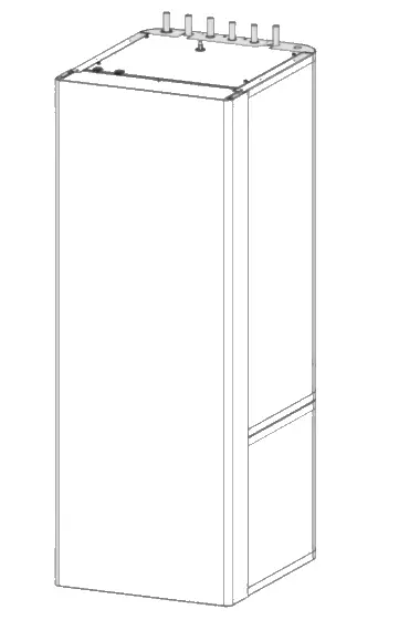
The buffer cylinder and DHW cylinder with indirect coil are arranged one above the other and can be separated for easier handling.
The appliance has a plastic jacket with foam insulation and is equipped with a removable front casing. The appliance is connected hydraulically and electrically to the heat pump. All hydraulic connections are made at the top and rear.
In addition to the DHW cylinder and the buffer cylinder, a highly efficient circulation pump is also integrated for a heating circuit without mixer.
DHW cylinder
The steel cylinder is coated on the inside with special direct enamel and is equipped with a signal anode. The anode with consumption indicator protects the cylinder interior from corrosion.
The heating water heated by the heat pump is pumped through an indirect coil inside the DHW cylinder. The heat channelled through the indirect coil is thus transferred to the domestic hot water.
Buffer cylinder
The steel cylinder provides hydraulic separation between the flow rates of heat pump and heating circuit. The heating water heated by the heat pump is transferred into the buffer cylinder. When a demand is issued, the integral heating circuit pump delivers the heating water to the heating circuit.
Cleaning, care and maintenance
- Have the electrical safety of the appliance and the function of the safety assembly regularly checked by a qualified contractor.
- Never use abrasive or corrosive cleaning agents. A damp cloth is sufficient for cleaning the appliance.
Signal anode with consumption indicator
Material losses
If the consumption indicator changes colour from white to red, have the signal anode checked by a qualified contractor and if necessary replaced.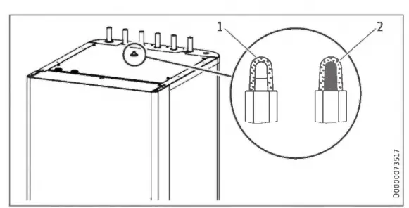
1 White = Anode OK
2 Red = Requires checking by qualified contractor
Scaling
Almost every type of water will deposit limescale at high temperatures. This settles inside the appliance and affects both performance and service life. A qualified contractor who knows the local water quality will tell you when the next service is due.
- Check the taps regularly. Limescale deposits at the tap outlets can be removed using commercially available descaling
- Regularly activate the safety valve to prevent it from becoming blocked, e.g. by limescale deposits.
Troubleshooting
Problem
The water does not heat up. The heating does not work.
Cause
There s no power.
Remedy
Check the fuses/MCBs in your distribution board.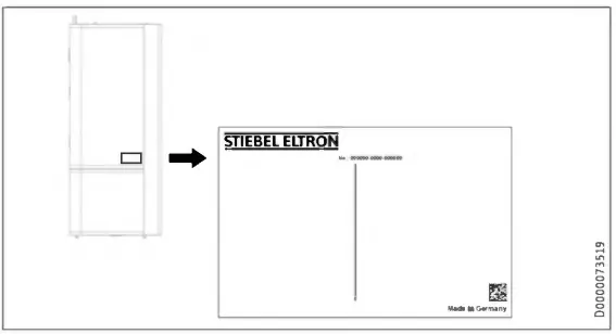
Safety
Only a qualified contractor should carry out installation, commissioning, maintenance and repair of the appliance.
7.1 General safety instructions
We guarantee trouble-free function and operational reliability only if original accessories and spare parts intended for the appliance are used.
7.2 Instructions, standards and regulations
Note
Observe all applicable national and regional regulations and instructions.
Appliance description
8.1 Standard delivery
The following are delivered with the appliance: – 4 adjustable feet
8.2 Accessories
Required accessories
Safety assemblies and pressure reducing valves are available to suit the prevailing supply pressure. These type-tested safety assemblies protect the appliance against impermissible excess pressure.
Additional accessories
- Pump assembly for a heating circuit with mixer HSBC-HKM – Pressure hoses
- Water softening fitting HZEA
- Temperature sensor PT1000 for area cooling
- STB-FB high limit safety cut-out for underfloor heating systems
Preparation
9.1 Installation location![]() Material losses
Material losses
Never install the appliance in wet rooms.
Install the appliance near the draw-off point in a dry room free from the risk of frost. To reduce line losses, keep the distance short between the appliance and the heat pump. Ensure the floor has sufficient load bearing capacity and evenness (for weight, see chapter “Specification / Data table”). The room must not be subject to a risk of explosions arising from dust, gases or vapours. If you are installing the appliance in a boiler room together with other heating equipment, ensure that the operation of the other heating equipment will not be impaired.
Minimum clearances 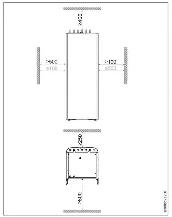
9.2 Transport and handling
Material losses Store and transport the appliance at temperatures be-tween -20 °C and +60 °C.
Handling
► Undo the 4 screws from the non-returnable pallet. 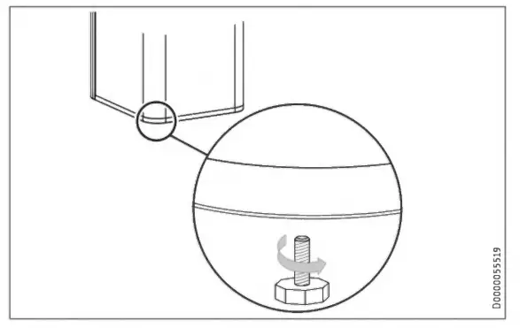
- Tilt the appliance and screw the 4 adjustable feet into the appliance.
- Lift the appliance off the pallet. If narrow doors or hallways hinder handling, you can separate the upper and lower sections of the appliance as described in the following chapters.
9.2.1 Removing/fitting the front casing 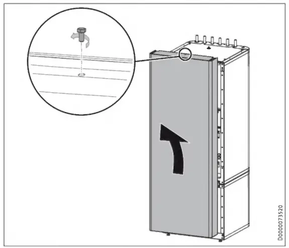
- Remove the screw at the top in the middle of the appliance.
- Unhook the front casing towards the top.
- Fit the front casing in reverse order.
9.2.2 Separating/joining the appliance sections
Separating the appliance sections
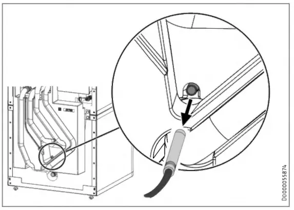
► Pull out the “heating sensor’ at the buffer cylinder.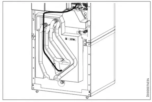 ► Release the sensor leads from the guide groove in the insula-tion segment.
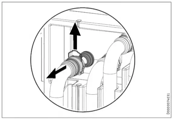 ► Disconnect the push-tit connectors of the 4 hydraulic con-nections. To do this, pull the spring clips fully out with a screwdriver.
► Pull the hydraulic connectors off forwards.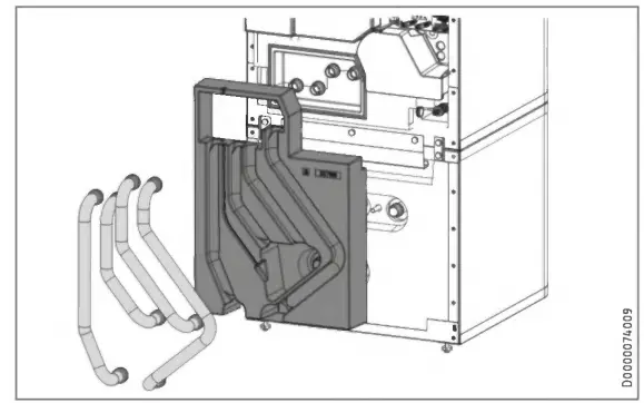 ► Remove the 4 hydraulic hoses and the insulation segment.
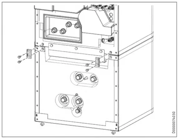 ► Release the 4 screws on the tabs at the front of the appliance.
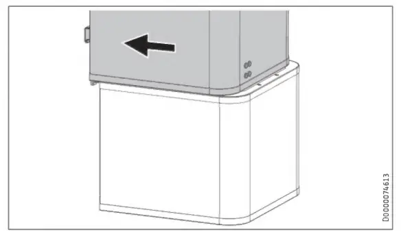 ► Pull the upper section of the appliance towards the front.
Handle
► Tip the upper section of the appliance backwards. Use the handle for improved grip.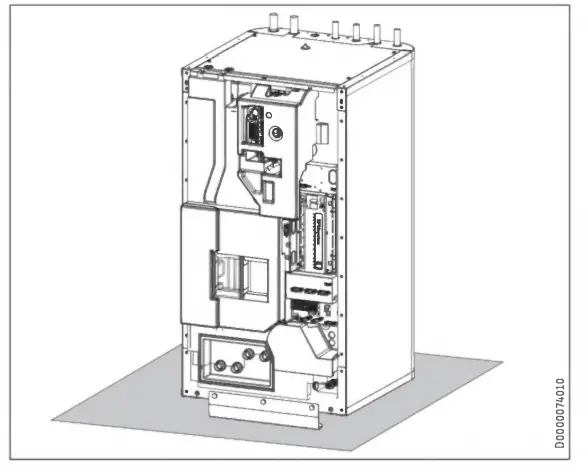 ► Place the upper section of the appliance on a base to prevent damage.
Appliance shutdown
 Material losses
Observe the temperature application limits and the min-imum circulation volume on the heat consumer side (see chapter “Specification / Data table”).Material losses
Drain the system when there is a risk of frost and the heat pump is completely switched off (see chapter “Mainte-nance / Draining the DHW cylinder”).
If you take the system out of use, set the heat pump manager to standby so that the safety functions that protect the appli-ance (e.g. frost protection) remain active.
Specification
Dimension and connection
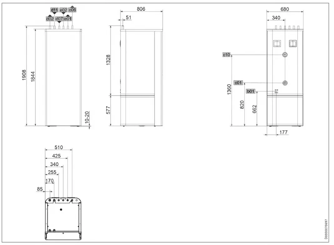
Other Dimension and connection
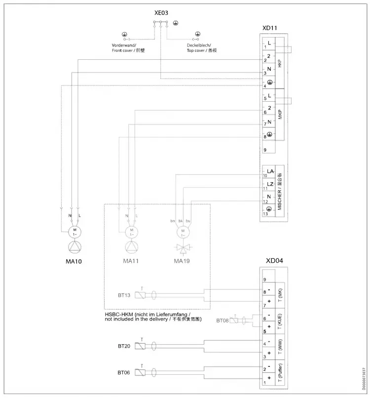
BTO6 Temperature sensor, heat pump buffer cylinder
BTO8 Temperature sensor, heat pump, cooling
BT13 Temperature sensor, heat pump flow / 211K (MK) (HSBC-HKM accessories)
BT20 Temperature sensor. DHW cylinder
MA10 Motor, heat pump heating circuit
MAll Motor, heat pump heating circuit 2 (HSBC-HKM accessories)
MA19 Motor, mixing valve heating circuit 2 (HSBC-HKM accessories)
X004 Terminal, external low voltage
XD11 Terminal, control unit
XE03 Earth terminal, control unit
Guarantee
The guarantee conditions of our German companies do not apply to appliances acquired outside of Germany. In countries where our subsidiaries sell our products a guarantee can only be issued by those subsidiaries. Such guarantee is only granted if the subsidiary has issued its own terms of guarantee. No other guarantee will be granted.
We shall not provide any guarantee for appliances acquired in countries where we have no subsidiary to sell our products. This will not affect warranties issued by any importers.
Environment and recycling
We would ask you to help protect the environment. After use, dispose of the various materials in accordance with national regulations.


