STIEBEL ELTRON SHW 200 S Floor Mounted Cylinder Installation Guide
SPECIAL INFORMATION
- The appliance may be used by children aged 8 and older and persons with reduced physical, sensory or mental capabilities or a lack of experience and know-how, provided that they are supervised or they have been instructed on howto use the appliance safely and have understood the resulting risks. Children must never play with the appliance. Children must never clean the appliance or perform user maintenance unless they are supervised.
- The connection to the power supply is only permissible as a permanent connection in conjunction with the removable cable grommet. Ensure the appliance can be separated from the power supply by an isolator that disconnects all poles with at least 3 mm contact separation.
- Observe the maximum permissible pressure (see chapter Installation / Specification / Data table).
- The appliance is pressurised. During the heat-up process, expansion water will drip from the safety valve.
- Regularly activate the safety valve to prevent it from becoming blocked, e.g. by limescale deposits.
- Drain the appliance as described in chapter “Installation / Maintenance / Draining the appliance”.
- Install a type-tested safety valve in the cold water supply line. Please note that, depending on the static pressure, you may also need a pressure reducing valve.
- Size the drain so that water can drain off unimpeded when the safety valve is fully opened.
- Fit the discharge pipe of the safety valve with a constant downward slope and in a room free from the risk of frost.
- The safety valve discharge aperture must remain open to atmosphere.
General information
The chapters “Special Information” and “Operation” are intended for both the user and qualified contractors.
The chapter “Installation” is intended for qualified contractors.
Note
Read these instructions carefully before using the appliance and retain them for future reference.
Pass on the instructions to a new user if required.
Safety instructions
Structure of safety instructions
KEYWORD Type of risk
Here, possible consequences are listed that may result from failure to observe the safety instructions.
Steps to prevent the risk are listed here.
Symbols, type of risk
Symbol | Type of risk |
Injury | |
| Electrocution | |
 | Burns (burns, scalding) |
Keywords
| KEYWORD | Meaning |
| DANGER | Failure to observe this information will result in serious injury or death. |
| WARNING | Failure to observe this information may result in serious injury or death. |
| CAUTION | Failure to observe this information may result in non-serious or minor injury. |
Other symbols in this documentation
![]() Note
Note
General information is identified by the symbol shown on the left.
- Read these texts carefully.
Symbol Meaning 
Material damage (Appliance and consequential losses, environmental pollution) 
Appliance disposal - This symbol indicates that you have to do something. The action you need to take is described step by step.
Units of measurement
Safety
Intended use
This pressure appliance is designed to heat DHW.
This appliance is designed for domestic use. It can be used safely by untrained persons. The appliance can also be used in a non-domestic environment, e.g. in a small business, as long as it is used in the same way.
Any other use beyond that described shall be deemed inappropriate. Observation of these instructions and of instructions for any accessories used is also part of the correct use of this appliance.
Any modifications or conversions to the appliance void all warranty rights.
General safety instructions
![]() WARNING Burns
WARNING Burns
There is a risk of scalding at outlet temperatures in excess of 43 °C.
![]() WARNING Injury
WARNING Injury
The appliance can be used by children aged 8 and above, as well as by persons with limited physical, sensory or mental abilities, or with a lack of experience and knowledge, provided they are supervised or have been instructed in the safe use of the appliance and understand the resulting dangers. Children must not play with the appliance. Cleaning and user maintenance may not be carried out by unsupervised children.
![]() Note
Note
The appliance is under pressure.
During the heat-up process, expansion water will drip from the safety valve. If water continues to drip when heating is completed, please inform your heating contractor.
Test symbols
See type plate on the appliance.
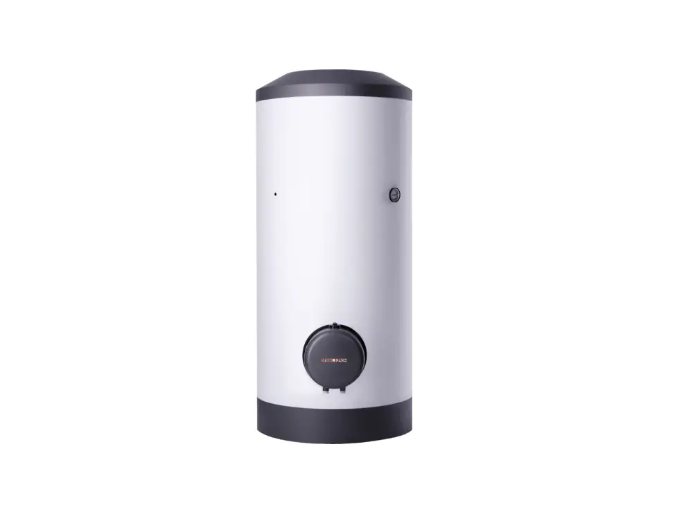
Appliance description
The appliance electrically heats domestic hot water, with the temperature controlled via the temperature selector. Subject to the power supply and operating mode, the water is heated automatically to the required temperature. You can use the appliance to supply one or several draw-off points.
The steel cylinder is coated on the inside with special directly applied enamel and is equipped with a thermometer and a protective anode. The anode with consumption indicator protects the cylinder interior from corrosion. The cylinder is enclosed by thermal insulation and a casing.
The appliance is also protected against frost on the temperature setting “cold” as long as the power supply is guaranteed. The appliance switches on in good time and heats the water. The water supply line and the safety assembly are not protected against frost by the appliance.
Single circuit operation
The appliance automatically heats up at any temperature setting subject to the availability of power.
Dual circuit operation
During off-peak tariff periods (cheap rate periods of power supply utilities), the appliance automatically heats up the water content with standard heating output at any temperature settings. In addition, you can switch on rapid heating during peak tariff periods.
Settings
The temperature is infinitely adjustable. Depending upon the system, the temperatures may vary from the set value.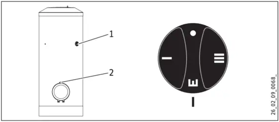
- Thermometer
- Temperature selector
- • Cold (frost protection)
- I Low temperature setting, 35 °C
- E Recommended energy saving position, low scaling, approx. 60 °C
- III Maximum temperature setting, 82 °C
Temperature selection is limited in the delivered condition. This limitation can be cancelled by a qualified contractor (see chapter “Installation / Settings”).
Dual circuit operation with rapid heat-up function
You can switch on rapid heating with the pushbutton whenever necessary. Rapid heating stops and will not restart once the selected temperature has been reached.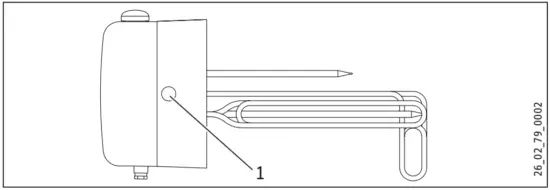
- Pushbutton for rapid heating
Cleaning, care and maintenance
- Have the electrical safety of the appliance and the function of the safety assembly regularly checked by a heating contractor.
- Never use abrasive or corrosive cleaning agents. A damp cloth is sufficient for cleaning the appliance.
Signal anode with consumption indicator
Material damage
If the consumption indicator changes colour from white to red, have the signal anode checked by a heating contractor and if necessary replaced.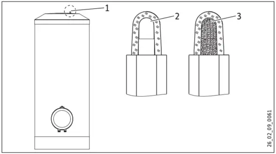
- Signal anode with consumption indicator
- White = anode OK
- Red = ask your heating contractor to check
Scaling
Almost every type of water deposits lime at high temperatures.
This settles inside the appliance and affects both the performance and service life. The heating elements must therefore be descaled from time to time. A qualified contractor who knows the local water quality will tell you when the next service is due.
- Check the taps/valves regularly. You can remove limescale deposits at the tap outlets using commercially available descaling agents.
- Regularly activate the safety valve to prevent it from becoming blocked e.g. by limescale deposits.
Troubleshooting
| Fault | Cause | Remedy |
| The water does not heat up. | There is no power. | Check the fuses/MCBs in your fuse box. |
| The flow rate is low. | The aerator in the tap or shower head is scaled up or contaminated. | Clean and/or descale the aerator or shower head. |
If you cannot remedy the fault, notify your heating contractor. To facilitate and speed up your enquiry, please provide the serial number from the type plate (no. 000000-0000-000000):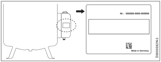
Safety
Only a qualified contractor should carry out installation, commissioning, maintenance and repair of the appliance.
General safety instructions
We guarantee trouble-free function and operational reliability only if the original accessories and spare parts intended for the appliance are used.
Instructions, standards and regulations
![]() Note
Note
Observe all applicable national and regional regulations and instructions.
Appliance description
Standard delivery
Delivered with the appliance:
- Thermometer (delivered inside the control panel)
- Cold water inlet pipe with flat gasket
- Adhesive rose for DHW circulation line
- Adaptor with flat gasket for the connection of a DHW circulation line
- Plastic cap
- Adjustable feet
Accessories
Required accessories
Depending on the static pressure, safety assemblies and pressure reducing valves are available. These type-tested safety assemblies protect the appliance against unacceptable excess pressure.
Further accessories
If it is not possible to fit an anode rod from above, install a segmented signal anode.
Preparations
Installation site
Always install the appliance in a room free from the risk of frost and near the draw-off point.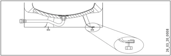
Use the adjustable feet to compensate for any unevenness in the floor.
Transport
![]() Material damage
Material damage
We recommend removing the cylinder casing during transport to the installation location, to prevent it from becoming dirty or damaged (see chapter “Installation / Fitting the cylinder casing and DHW circulation line if required”).
Installation
Fitting the cylinder casing and DHW circulation line if required
![]() Note
Note
Fit the cylinder casing with cover before making the water connection and, if necessary, the DHW circulation line or the flanged immersion heater.
The plinth trim should be fitted after the tightness check.
A DHW circulation line can be fitted to the “DHW circulation” connection (see chapter “Specification / Dimensions and connections”). Alternatively, the “DHW circulation” connection can be used to connect a thermometer.
Dismantling
- Remove the cover and the plinth trim of the cylinder casing one after the other.
- Pull off the temperature selector on the flanged immersion heater.
- Remove the control panel cover and cable grommet.
- Remove the cylinder casing.
Installation
- Fit the cylinder casing.
- Fit the cable grommet and control panel cover.
- Push on the temperature selector.
- If you use the “DHW circulation” connection to install a DHW circulation line, you need to cut an opening in the cylinder casing near the connection (indentation in the foam) for the DHW circulation line.
- Remove the thermal insulation near the connection.
- Route the DHW circulation line through the aperture in the cylinder casing and fit the DHW circulation line.
- Insulate the “DHW circulation” connection.
- Insert the supplied adaptor with flat gasket and an extension.
- Cover the hole in the cylinder casing with the adhesive rose supplied.
- Fit the cover and the plinth trim of the cylinder casing.
Thermometer
- Insert the thermometer as far as it will go and align it.
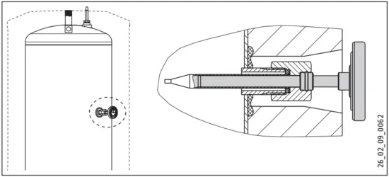
Signal anode
![]() Material damage
Material damage
The appliance must not be operated without a consumption indicator or with a damaged one, otherwise water will leak out once the anode is depleted.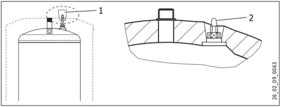
- Transport protection
- Signal anode with consumption indicator
- Remove the transport protection.
- Check the consumption indicator for transport damage.
Water connection and safety assembly
Safety instructions
![]() Note
Note
Carry out all water connection and installation work in accordance with regulations.
![]() Material damage
Material damage
When using plastic pipework, observe chapter “Specification / Fault conditions”.
![]() Material damage
Material damage
Operate the appliance only with pressure-tested taps
Cold water line
Galvanised steel, stainless steel, copper and plastic are approved materials.
A safety valve is required.
DHW line
Stainless steel, copper and plastic pipework are approved materials.
Connection
- Flush the pipes thoroughly.
The max. permissible pressure must not be exceeded (see chapter “Specification / Data table”). - Install a type-tested safety valve in the cold water supply line. Please note that, depending on the static pressure, you may also need a pressure reducing valve.
- Fit the DHW outlet pipe and the cold water inlet pipe. Connect the hydraulic connections with flat gaskets.

- Cold water connection
- Cold water supply pipe
- Connect the cold water supply directly to the cylinder or with the connecting pipe routed between the cylinder feet.
- During fitting, counterhold the fitting with an open-ended spanner (size 36).
- Check the rigidity of the connecting pipe and secure it further if required.
- Size the drain so that water can drain off unimpeded when the safety valve is fully opened.
- Fit the discharge pipe of the safety valve with a constant downward slope and in a room free from the risk of frost.
- The safety valve discharge aperture must remain open to the atmosphere.
Power supply
![]() WARNING Electrocution
WARNING Electrocution
Before any work on the appliance, disconnect all poles from the power supply.
![]() WARNING Electrocution
WARNING Electrocution
The connection to the power supply is only permissible as a permanent connection in conjunction with the removable cable entry. Ensure that the appliance can be separated from the power supply by an isolator that disconnects all poles with at least 3 mm contact separation.
![]() WARNING Electrocution
WARNING Electrocution
Ensure that the appliance is earthed.
![]() WARNING Electrocution
WARNING Electrocution
Install a residual current device (RCD).
![]() Material damage
Material damage
Observe the type plate. The specified voltage must match the mains voltage.
- Pull off the temperature selector.
- Undo the screws at the bottom of the control panel cover and remove the cover.
- Prepare the power cable and feed it through the cable grommet into the control panel. Select a cable with a cross-section suited to the load of the appliance.
![]() Note
Note
If you connect the appliance for 3 kW output, two heating elements are connected in series and the surface load is reduced. This can significantly prolong the service life of the electric heating elements, particularly in areas with a water hardness level of 14 °dH or higher.
- Connect the required load in accordance with the connection examples (see chapter “Specification / Wiring diagrams and connections”).
- Fit the control panel cover.
- Push on the temperature selector.
- If the power supply utility does not permit rapid heating, cover the pushbutton with the plastic cap provided.
- Use a ballpoint pen to mark the selected connected load and voltage on the type plate.
Commissioning
Commissioning
- Open a draw-off point until the appliance has filled up and the pipework is free of air.
- Adjust the flow rate. For this, observe the maximum permissible flow rate with a fully opened tap (see chapter “Specification / Data table”). If necessary reduce the flow rate at the butterfly valve of the safety assembly.
- Carry out a tightness check.
- Turn the temperature selector to maximum temperature.
- Switch the mains power ON.
- Check the function of the appliance.
- Check the function of the safety assembly.
Appliance handover
- Explain the appliance function to users and familiarise them with its operation.
- Make the user aware of potential dangers, especially the risk of scalding.
- Hand over these instructions.
Recommissioning
See chapter “Commissioning”.
Settings
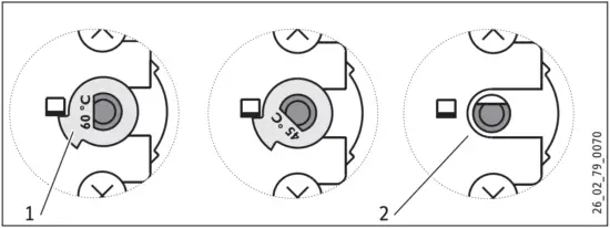
Limiting the temperature selection
You can adjust the temperature selection limitation beneath the temperature selector.
Factory setting: Limited to 60 °C
- Set the temperature selector to “cold” and isolate the appliance from the power supply.
- Remove the temperature selector and the control panel cover.

- You can set the limit to 45 °C / 60 °C by rotating the limiter disc. After removing the limiter disc, the maximum temperature can be set.
- Replace the control panel cover and temperature selector.
Shutting down
- Disconnect the appliance from the mains at the MCB/fuse in the fuse box.
- Drain the appliance. See chapter “Maintenance / Draining the appliance”.
Troubleshooting
![]() Note
Note
The high limit safety cut-out can respond at temperatures below –15 °C. The appliance may be subjected to these temperatures during storage or transport.
| Fault | Cause | Remedy |
| The water does not heat up. | The high limit safety cut-out has responded because the controller is faulty. | Replace the thermostat and press the high limit safety cut-out reset button. |
| The high limit safety cutout has responded because the temperature has dropped below -15 °C. | Press the reset button. | |
| A heating element is faulty. | Replace the flanged immersion heater. | |
| Rapid heating does not switch on. | Check the contactor and replace if required. | |
| The safety valve drips when the heating is switched off. | The valve seat is contaminated. | Clean the valve seat. |
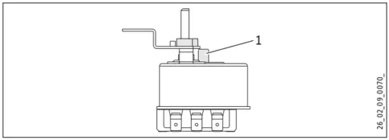
- High limit safety cut-out reset button
Maintenance
![]() WARNING Electrocution
WARNING Electrocution
Carry out all electrical connection and installation work in accordance with relevant regulations.
![]() WARNING Electrocution
WARNING Electrocution
Before any work on the appliance, disconnect all poles of the appliance from the power supply.
If you need to drain the appliance, observe chapter “Draining the appliance”.
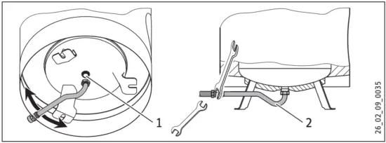
Checking the safety valve
- Regularly vent the safety valve on the safety assembly until a full water jet is discharged.
Draining the appliance
![]() WARNING Burns
WARNING Burns
Hot water may escape during the draining process.
If the cylinder needs to be drained for maintenance or to protect the whole installation when there is a risk of frost, proceed as follows:
- Close the shut-off valve in the cold water line.
- Open the hot water taps on all draw-off points.
- Drain the appliance via the safety assembly.
Replacing the signal anode
- Replace the signal anode if it becomes depleted.
Cleaning and descaling the appliance
- Never use descaling pumps.
- Only descale the flanged immersion heater after dismantling and never treat the cylinder surface or protective anode with descaling agents.
Torque of the flange screws: see chapter “Specification / Dimensions and connections”
Replacing flanged immersion heater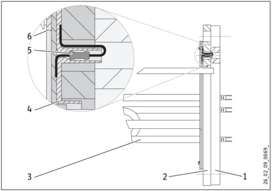
- Insulation plate
- Flange plate
- Soldered flange
- Insulating plate
- Corrosion resistor 390 Ω
- Gasket
Specification
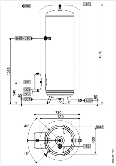
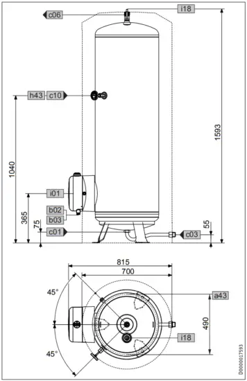
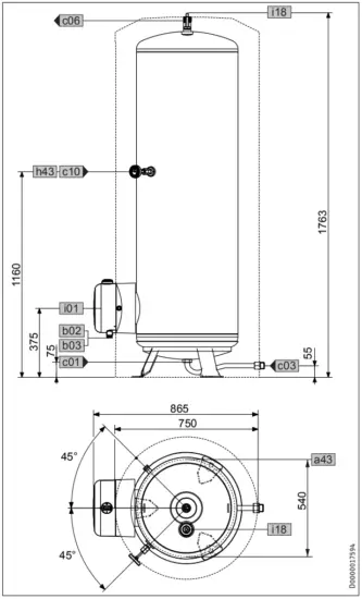
Dimensions and connections
- SHW 200 S

SHW 200 S a43 Appliance Pitch circle diameter of feet mm 430 a45 Feet fixing hole Diameter mm 19 b02 Entry electrical cables I Diameter PG 16 b03 Entry electrical cables II Diameter PG 13.5 c01 Cold water inlet Male thread G 1 A c03 Cold water inlet pipe Male thread G 1 A Torque Nm 100 c06 DHW outlet Male thread G 1 A c10 DHW circulation Male thread G 1/2 A h43 Thermometer Diameter mm 15. i01 Flange Diameter mm 210 Pitch circle diameter mm 180 Screws M12 Torque Nm 55 i18 Protective anode Female thread G 3/4 - SHW 300 S75

mm SHW 300 S a43 Appliance Pitch circle diameter of feet 490 a45 Feet fixing hole Diameter mm 19 b02 Entry electrical cables I Diameter PG 16 b03 Entry electrical cables II Diameter PG 13.5 c01 Cold water inlet Male thread G1A c03 Cold water inlet pipe Male thread G1A Torque Nm 100 c06 DHW outlet Male thread G1A c10 DHW circulation Male thread G 1/2 A h43 Thermometer Diameter mm 15. 101 Flange Diameter mm 210 Pitch circle diameter mm 180 Screws M12 Torque Nm 55 i18 Protective anode Female thread G 3/4 - SHW 400 S75

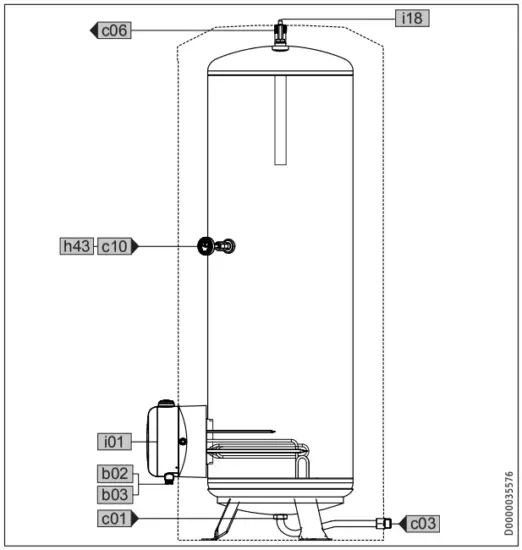
SHW 400 S a43 Appliance Pitch circle diameter of feet mm 540 a45 Feet fixing hole Diameter mm 19 b02 Entry electrical cables I Diameter PG 16 b03 Entry electrical cables II Diameter PG 13.5 c01 Cold water inlet Male thread G 1 A c03 Cold water inlet pipe Male thread G 1 A Torque Nm 100 c06 DHW outlet Male thread G 1 A c10 DHW circulation Male thread G 1/2 A h43 Thermometer Diameter mm 15. i01 Flange Diameter mm 210 Pitch circle diameter mm 180 Screws M12 Torque Nm 55 i18 Protective anode Female thread G 3/4 - Appliance sectional view

Wiring diagrams and connections
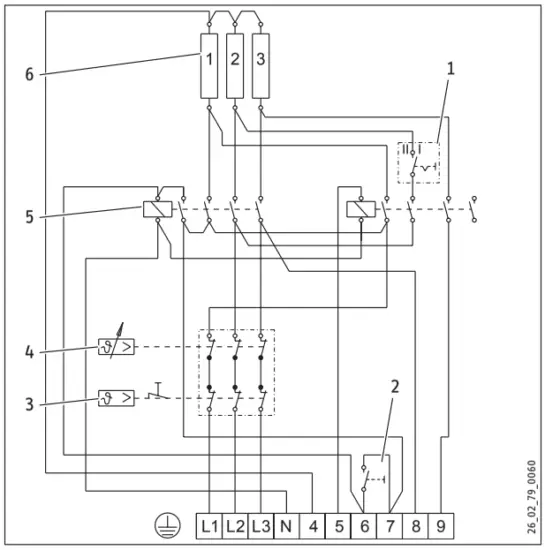
- Circuit breaker in the control panel
- Pushbutton for rapid heating
- High limit safety cut-out
- Temperature controller
- Contactor
- Heating element, 2 kW ~ 230 V each
Dual circuit operation, single meter measurement with power supply utility contact
In the following connection examples, the rapid heating output during peak tariff periods is given after the forward slash.
Note the position of the circuit breaker in the control panel.
2/4 kW: Switch position I: 1/N/PE ~ 230 V
4/4 kW: Switch position Il: 1/N/PE ~ 230 V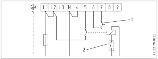
2/6 kW: Switch position I: 3/N/PE ~ 400 V
3/6 kW Switch position I 3/N/PE ~ 400 V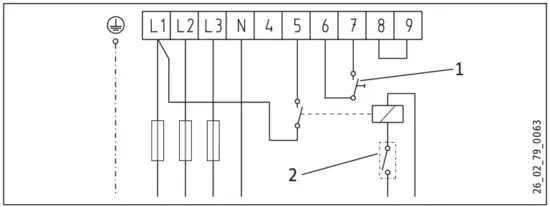
4/6 kW Switch position I 3/N/PE ~ 400 V
6/6 kW Switch position Il 3/N/PE ~ 400 V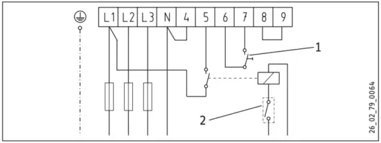
- Pushbutton for rapid heating
- Power supply utility contact
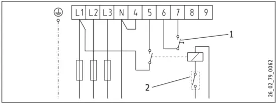
Single circuit operation
In the following connection examples, the output of the rapid heater is given in brackets.
Note the position of the circuit breaker in the control panel.
2(4) kW Switch position I 1/N/PE ~ 230 V
4(4) kW Switch position Il 1/N/PE ~ 230 V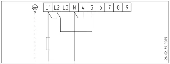
2(6) kW Switch position I 3/N/PE ~ 400 V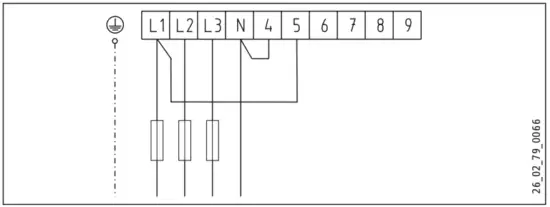
3(6) kW Switch position I 3/N/PE ~ 400 V
4(6) kW Switch position I 3/N/PE ~ 400 V
6(6) kW Switch position Il 3/N/PE ~ 400 V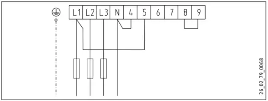
Dual circuit operation, dual meter measurement with power supply utility contact
1/N/PE ~ 230 V
3/N/PE ~ 400 V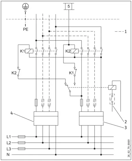
K1 Contactor 1
K2 Contactor 2
- Connections also required for 3/N/PE ~ 400 V
- Power supply utility contact
- Off-peak tariff meter
- Peak tariff meter
Ensure connection to the same phase.
Details on energy consumption
| SHW 200 S | SHW 300 S | SHW 400 S | ||
| 182120 | 182121 | 182122 | ||
| Manufacturer | STIEBEL ELTRON | STIEBEL ELTRON | STIEBEL ELTRON | |
| Load profile | XL | XL | XL | |
| Energy efficiency class | C | C | C | |
| Energy conversion efficiency | ok, | 39 | 39 | 39 |
| Annual power consumption | kWh | 4294 | 4311 | 4268 |
| Default temperature setting | °C | 60 | 60 | 60 |
| Sound power level | dB(A) | 15 | 15 | 15 |
| Option for exclusive operation during off-peak periods | ||||
| Special information on measuring efficiency | ||||
| Smart function | ||||
| Cylinder capacity | I | 200 | 300 | 400 |
| Mixed water volume at 40 °C | I | 392 | 582 | 768 |
| Daily power consumption | kWh | 20. | 20. | 20. |
Heat-up diagram
The heat-up time depends on the cylinder capacity, cold water inlet temperature and heating output.
At 10 °C cold water temperature and temperature setting “E”: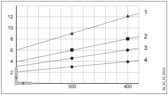
X Nominal capacity [I]
Y Duration [h]
- 2 kW
- 3 kW
- 4 kW
- 6 kW
Fault conditions
In the event of a fault, temperatures of up to 95 °C at 0.6 MPa can occur.
Data table
| SHW 200 S | SHW 300 S | SHW 400 S | ||
| 182120 | 182121 | 182122 | ||
| Hydraulic data | ||||
| Nominal capacity | 1 | 200 | 300 | 400 |
| Amount of mixed water 40 °C (15 °C/65 °C) | 1 | 392. | 582. | 768. |
| Electrical data | ||||
| Connected load — 230 V | kW | 2-4 | 2-4 | 2-4 |
| Connected load — 400 V | kW | 2-6 | 2-6 | 2-6 |
| Rated voltage | V | 230/400 | 230/400 | 230/400 |
| Phases | 1/N/PE,3/N/PE | 1/N/PE,3/N/PE | 1/N/PE,3/N/PE | |
| Frequency | Hz | 50/60 | 50/60 | 50/60 |
| Single circuit operating mode | X | X | X | |
| Dual circuit operating mode | X | X | X | |
| Application limits | ||||
| Temperature setting range | °C | 35-82 | 35-82 | 35-82 |
| Max. permissible pressure | MPa | 0.6 | 0.6 | 0.6 |
| Test pressure | MPa | 0.78 | 0.78 | 0.78 |
| Max. permissible temperature | °C | 95 | 95 | 95 |
| Max. flow rate | l/min | 30 | 38 | 45 |
| Min./max. conductivity, drinking water | pS/cm | 100-1500 | 100-1500 | 100-1500 |
| Energy data | ||||
| Standby energy consumption/24 h at 65 °C | kWh | 2. | 2. | 2. |
| Energy efficiency class | C | C | C |
| Versions | ||||
| IP rating | IP24 | IP24 | IP24 | |
| Sealed unvented type | X | X | X | |
| Colour | pure white/basalt grey | pure white/basalt grey | pure white/basalt grey | |
| Dimensions Height | MITI | 1578 | 1593 | 1763 |
| Width | mm | 630 | 700 | 750 |
| Depth | mm | 730 | 815 | 865 |
| Weight | ||||
| Weight, full | kg | 265 | 377 | 490 |
| Weight, empty | kg | 65 | 77 | 90 |
Guarantee
The guarantee conditions of our German companies do not apply to appliances acquired outside of Germany. In countries where our subsidiaries sell our products a guarantee can only be issued by those subsidiaries. Such guarantee is only granted if the subsidiary has issued its own terms of guarantee. No other guarantee will be granted.
We shall not provide any guarantee for appliances acquired in countries where we have no subsidiary to sell our products.
This will not affect warranties issued by any importers.
Environment and recycling
We would ask you to help protect the environment. After use, dispose of the various materials in accordance with national.


