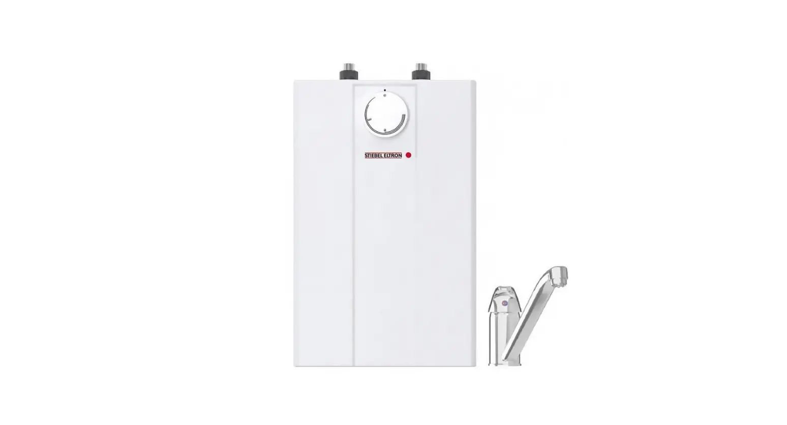
Stiebel Eltron ESH 10 U-P Plus small water heater Installation Guide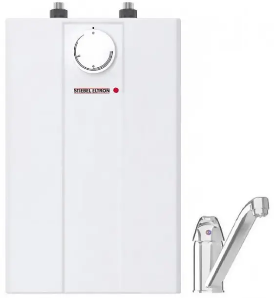
Special Information
- The appliance may be used by children over 3 years of age and persons with reduced physical, sensory or mental capabilities or a lack of experience and expertise, provided that they are supervised or they have been instructed on how to use the appliance safely and have understood the potential risks. Children aged 3 to 8 years may only operate the tap connected to the appliance. Children must never play with the appliance. Children must never clean the appliance or perform user maintenance unless they are supervised.
- When permanently connected to the power supply using a dedicated junction box, the appliance must be able to be isolated from the mains power supply by an isolator that disconnects all poles with at least 3 mm contact separation.
- The power cable may only be replaced (for example if damaged) by a qualified contractor authorised by the manufacturer, using an original spare part.
- Secure the appliance as described in chapter “Installation / Installation”.
- Observe the maximum permissible pressure (see chapter “Installation / Specification / Data table”).
- The appliance is pressurised. During the heatup process, expansion water will drip from the safety valve.
- Regularly activate the safety valve to prevent it from becoming blocked, e.g. by limescale deposits.
- Drain the appliance as described in chapter “Installation / Maintenance / Draining the appliance”.
- Install a type-tested safety valve, or safety assembly containing such a safety valve, in the cold water supply line.
- Size the drain pipe so that water can drain off unimpeded when the safety valve is fully opened
- Fit the drain pipe of the safety valve with a constant downward slope and in a room free from the risk of frost.
- The safety valve drain must remain open to the atmosphere.
General information
The chapters “Special information” and “Operation” are intended for both users and qualified contractors. The chapter “Installation” is intended for qualified contractors.
![]() Note
Note
Read these instructions carefully before using the appliance and retain them for future reference. Pass on the instructions to a new user if required.
Safety instructions
Structure of safety instructions
![]() KEYWORD Type of risk Here, possible consequences are listed that may result from failure to observe the safety instructions. ff Steps to prevent the risk are listed.
KEYWORD Type of risk Here, possible consequences are listed that may result from failure to observe the safety instructions. ff Steps to prevent the risk are listed.
Symbols, type of risk
![]() Injury
Injury![]() Electrocution
Electrocution![]() Burns (burns, scalding)
Burns (burns, scalding)
Keywords
| Keywords | Meaning |
| DANGER | Failure to observe this information will result in serious injury or death. |
| WARNING | Failure to observe this information may result in serious injury or death |
| CAUTION | Failure to observe this information may result in non-serious or minor injury. |
Other symbols in this documentation
![]() Note
Note
General information is identified by the adjacent symbol.
Read these texts carefully.
| Symbol | Meaning |
| Material losses (appliance damage, consequential losses and environmental pollution) |
 | Appliance disposal |
This symbol indicates that you have to do something. The action you need to take is described step by step.
Units of measurement
![]() Note All measurements are given in mm unless stated otherwise
Note All measurements are given in mm unless stated otherwise
Safety
Intended use
This sealed unvented (pressurised) appliance is intended for heating domestic hot water. You can use the appliance to supply one or more draw-off points.
The appliance is intended for domestic use. It can be used safely by untrained persons. The appliance can also be used in non-domestic environments, e.g. in small businesses, as long as it is used in the same way.
Any other use beyond that described shall be deemed inappropriate. Observation of these instructions and of the instructions for any accessories used is also part of the correct use of this appliance.
Safety instructions
![]() WARNING Burns
WARNING Burns
During operation, the tap can reach temperatures in excess of 60 °C. There is a risk of scalding at outlet temperatures in excess of 43 °C. !
![]() WARNING Injury
WARNING Injury
The temperature selector should only be removed by a qualified contractor. !
![]() WARNING Injury
WARNING Injury
The appliance may be used by children over 3 years of age and persons with reduced physical, sensory or mental capabilities or a lack of experience and expertise, provided that they are supervised or they have been instructed on how to use the appliance safely and have understood the potential risks. Children aged 3 to 8 years may only operate the tap connected to the appliance. Children must never play with the appliance. Children must never clean the appliance or perform user maintenance unless they are supervised.
![]() Material losses
Material losses
If the drain pipe of the safety valve is blocked, expanding water can lead to water damage.
Never close the drain pipe.
![]() Material losses
Material losses
The user should protect the appliance and its tap against frost.
Test symbols
See type plate on the appliance.
Appliance description
The appliance constantly keeps the water content available at the preselected temperature. The appliance switches on automatically as soon as its temperature falls below the set value. Subject to season, varying cold water temperatures can result in different maximum amounts of mixed outlet water.
![]() Note
Note
The appliance is under mains water pressure. The water volume increases as the cylinder is being heated up. During this process, expansion water drips through the safety valve. This is a necessary and normal process.
Operation
You can set any required DHW outlet temperature variably at the temperature selector. The heat-up indicator illuminates during the heat-up process.
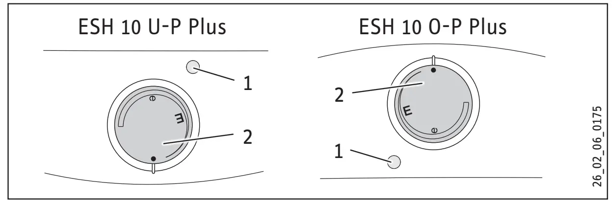
- Heat-up indicator
- Temperature selector
Depending on the system, the actual temperatures may vary from the set value.
- • = Cold. On this setting, the appliance is protected from frost. The tap and the water line are not protected.
- E = Approx. 40 °C
- e = Recommended energy saving setting (approx. 60 °C), minor scaling
Cleaning, care and maintenance
- Never use abrasive or corrosive cleaning agents. A damp cloth is sufficient for cleaning the appliance.
- Check the taps regularly. Limescale deposits at the tap outlets can be removed using commercially available descaling agents.
- Have the function of the safety valve checked regularly by a qualified contractor.
- Have the protective anode checked by a qualified contractor after the first 2 years of operation. The qualified contractor will then determine the intervals at which repeat checks should be performed.
Almost every type of water will deposit limescale at high temperatures. This settles inside the appliance and affects both performance and service life. The heating elements should therefore be descaled if necessary. A qualified contractor who is aware of the local water quality will tell you when the next descaling is due.
Troubleshooting
| Fault | Cause | remedy |
| The appliance does not supply hot water. | The temperature selector is set to “•” | Switch the appliance ON by turning the temperature selector. |
| No power at the appliance. | Check the plug / fuses in the distribution board. | |
| Water can only be drawn at a reduced rate. | The aerator in the tap is scaled up. | Descale / replace the aerator. |
| Loud boiling noises inside the appliance. | The appliance is scaled up | Have the appliance descaled by a qualified contractor |
| Water drips from the safety valve of the safety assembly after heating has stopped | The safety valve is scaled up or dirty | Switch the appliance off. Depressurise the appliance by disconnecting it from the power and water supply. Have the safety valve checked by a qualified contractor. |
If you cannot remedy the fault, contact your qualified contractor. To facilitate and speed up your enquiry, please provide the serial number from the type plate (000000-0000-000000).
Safety
Only a qualified contractor should carry out installation, commissioning, maintenance and repair of the appliance.
General safety instructions
We guarantee trouble-free function and operational reliability only if original accessories and spare parts intended for the appliance are used.
Instructions, standards and regulations
![]() Note
Note
Observe all applicable national and regional regulations and instructions.
Information on the safety valve
![]() v Material losses
v Material losses
Never exceed the operating pressure. !
![]() Material losses
Material losses
Install a type-tested safety valve, or safety assembly containing such a safety valve, in the cold water supply line. !
![]() Material losses
Material losses
Route the drain pipe of the safety valve with a slope and leave it open to the atmosphere. !
![]() Material losses
Material losses
The safety equipment requires regular maintenance and activation (see installation instructions of the safety valve).
Appliance description
The appliance is intended for heating cold water and to supply one or more draw-off points.
ESH 10 U-P Plus
The sealed unvented (pressurised) appliance is only suitable for undersink installation.
ESH 10 O-P Plus
The sealed unvented (pressurised) appliance is only suitable for oversink installation.
The appliance may only be installed with pressure taps and in conjunction with the type-tested diaphragm safety valve with non-return valve (see chapter “Installation / Appliance description / Standard delivery”)
The enamelled steel inner cylinder is equipped with a protective anode. The protective anode protects the inner cylinder against corrosion.
Standard delivery
The following are delivered with the appliance:
- Wall mounting bracket
- Diaphragm safety valve with non-return valve
ESH 10 U-P Plus
- 2x reducers G1/2 – G3/8 incl. flat gaskets
Preparation
Water installation
A diaphragm safety valve with non-return valve is required.
Taps
Only install pressure taps in conjunction with the diaphragm safety valve.
Installation site
![]() Material losses
Material losses
Install the appliance in a room free from the risk of frost.
![]() Material losses
Material losses
Mount the appliance on the wall. The wall must have sufficient load bearing capacity.
Always install the appliance vertically and near the draw-off point.
ESH 10 U-P Plus – undersink installation
Note
The appliance is only suitable for undersink installation. The water connections of the appliance are at the top.
ESH 10 O-P Plus – oversink installation
Note
The appliance is only suitable for oversink installation. The water connections of the appliance point downwards.
Installation
Material losses
When using plastic pipework observe the extreme operating and fault conditions that can occur on the appliance (see chapter “Installation / Specification / Extreme operating and fault conditions”).
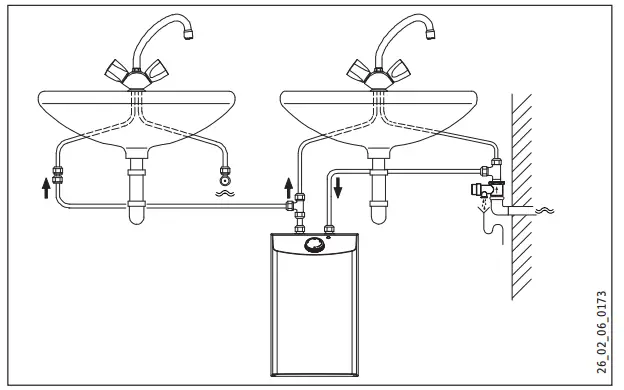
Run the connections to the second tap on site, e.g. in 10 mm copper pipe.
ESH 10 U-P Plus
To supply two washbasins, use water distribution tees.
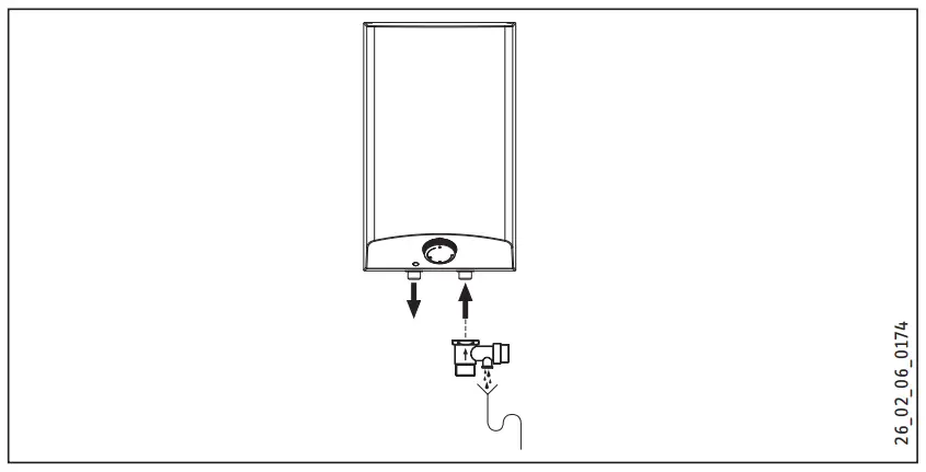
Installing the safety assembly
- Fit the diaphragm safety valve in the cold water supply line of the appliance.
- Observe the information on the safety valve (see chapter “Installation / Safety / Information on the safety valve”).
- Observe the information in the installation instructions of the safety valve.
- Fit a pressure reducer upstream of the diaphragm safety valve in the cold water supply line if the supply pressure exceeds 0.48 MPa.
Appliance installation
- Mark out the holes to be drilled on the wall (see chapter “Installation / Specification / Dimensions and connections”).
- Drill the holes and insert suitable rawl plugs.
- Secure the wall mounting bracket using suitable screws.
- Hang the appliance on the wall mounting bracket.
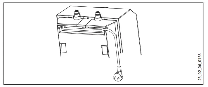
![]() Note
Note
Surplus cable can be stored in the cable compartment.
Water connection
![]() Material losses
Material losses
Carry out all water connection and installation work in accordance with regulations.!
![]() Material losses
Material losses
The appliance may lose its function.
- Never interchange the water connections.
- Set the flow rate (see safety valve instructions).
Observe the maximum permissible flow rate with a fully opened tap (see chapter “Installation / Specification / Data table”).
Match up the colour coding on the tap water connections and the appliance:
- R.h. side blue = “Cold water inlet”
- L.h. side red = “DHW outlet”
Secure the water connections from the tap to the appliance.
If necessary, screw the reducers supplied, incl. flat gaskets, onto the appliance connectors.
Note
Ensure that the water connections are not kinked during installation. Prevent any tensioning during installation.
Electrical connection
![]() WARNING ELECTROCUTION
WARNING ELECTROCUTION
Carry out all electrical connection and installation work in accordance with relevant regulations.
![]() WARNING ELECTROCUTION
WARNING ELECTROCUTION
When permanently connected to the power supply using a dedicated junction box, the appliance must be able to be isolated from the mains power supply by an isolator that disconnects all poles with at least 3 mm contact separation.
![]() WARNING ELECTROCUTION
WARNING ELECTROCUTION
Ensure that the appliance is earthed.
![]() Material losses
Material losses
The voltage specified on the type plate must match the mains voltage.
Observe the type plate.
The following electrical connections are permissible:
| ESH 10 U-P Plus | ESH 10 O-P Plus | |
| Connection to a freely accessible standard socket with matching plug | X | X |
| Permanent connection to an appliance junction box with earth conductor | X | X |
Commissioning
WARNING ELECTROCUTION
Commissioning may only be carried out by a qualified contractor in accordance with safety regulations.
Initial start-up
Material losses
If you fail to follow the correct sequence (first water, then power), the high limit safety cut-out will trip. Proceed as follows:
- If necessary, replace the temperature controller.
- Make the high limit safety cut-out operational by pressing the reset button (see chapter “Installation / Troubleshooting / Activating the high limit safety cut-out”).
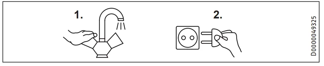
- Either open the DHW valve of the tap or set the mono lever mixer tap to “hot” until the water that flows out is free of air bubbles.
- Check the diaphragm safety valve. When purging, ensure that a full jet of water flows out.
- Insert the plug into the standard socket or set the fuse/MCB in the distribution board.
- Select a temperature.
- Check the water connections for tightness.
Appliance handover
- Explain the functions of the appliance to the user. Show the user how to operate the appliance.
- Make the user aware of potential dangers, especially the risk of scalding.
- Hand over these instructions and, if applicable, the instructions for any accessories.
Recommissioning
See chapter “Installation / Commissioning / Initial start-up”.
Appliance shutdown
- Isolate the appliance from the power supply by removing the plug or by tripping the MCB in the distribution board.
- Drain the appliance (see chapter “Installation / Maintenance / Draining the appliance”).
Troubleshooting
| Fault | Cause | remedy |
| The appliance does not supply hot water | The high limit safety cut-out has tripped. | Remedy the cause of the fault. If necessary, replace the temperature controller. Reset the high limit safety cut-out by pressing its reset button. |
| Loud boiling noises inside the appliance | The appliance is scaled up. | Descale the appliance. |
Activate high limit safety cut-out
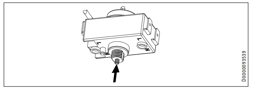
Push the reset button.
Maintenance
![]() WARNING Electrocution
WARNING Electrocution
Before any work on the appliance, disconnect all poles of the appliance from the power supply.
- Dismantle the appliance for maintenance work.
- Observe the tightening torque of the flange screws (see chapter “Installation / Maintenance / Installing the flanged immersion heater”).
Draining the appliance
![]() WARNING Burns
WARNING Burns
Hot water may escape during draining.
Drain the appliance via its connectors.
Opening the appliance
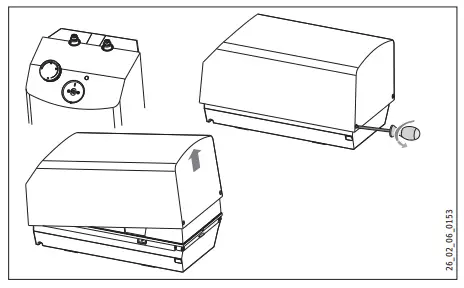
- Pull off the temperature selector.
- Remove the screws from underneath the temperature selector.
- Open the appliance cover by lowering the bolt screws inwards and pivot the cover upwards, then remove it.
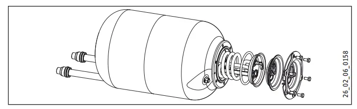
Installing the flanged immersion heater
Torque value of the flange screws
Checking the protective anode
- Check the protective anode for the first time 2 years after installation. This requires removal of the flanged immersion heater. Replace the protective anode if consumed.
- Decide the intervals in which further checks should be carried out.
Fitting the protective anode
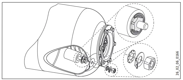
To include the steel cylinder in the equipotential bonding, observe the order of the fixing elements when fitting the protective anode.
Descaling the appliance
Material losses
Never treat the protective anode with descaling agents.
- Remove the flanged immersion heater.
- Carefully tap the heating element to remove coarse limescale deposits.
- Immerse the heating element up to the flange plate in descaling agent.
Checking the earth conductor
Check the earth conductor (in Germany DGUV3 for example) across a water connector and the earth conductor contact of the power cable.
Replacing the power cable
The power cable must only be replaced by a qualified contractor with an original spare part.
Note
Never remove the plastic thread holding the profile plate.
Positioning the temperature sensor in its protective pipe
When replacing the temperature controller and the high limit safety cut-out, guide the temperature sensors into the protective pipe.
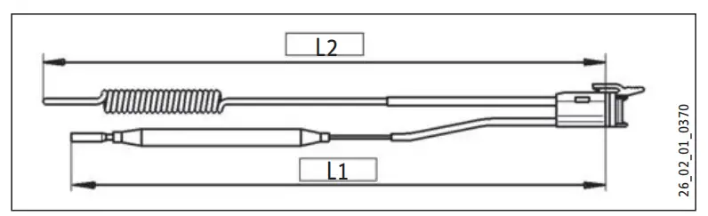
L1 Temperature controller
L2 High limit safety cut-out
| L1 | L2 | |
| ESH 10 U-P Plus | 160 | 180 |
| ESH 10 O-P Plus | 250 | 160 |
Specification
Dimensions and connections
ESH 10 U-P Plus
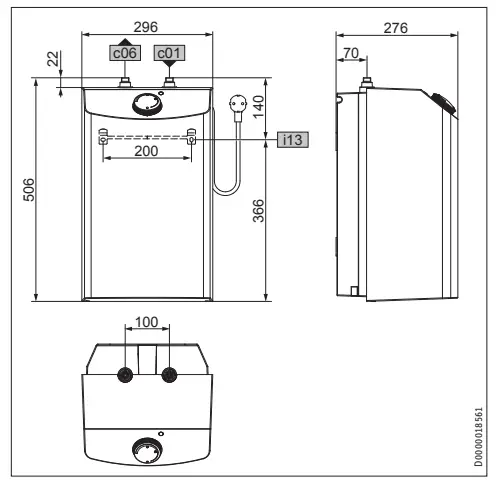
| ESH 10 U-P Plus | |||
| c01 | Cold water inlet | Male thread | G 3/8 A* |
| c06 | DHW outlet | Male thread | G 3/8 A* |
| i13 | Wall mounting bracket | / | / |
Reducers G1/2 – G3/8 in the standard delivery
ESH 10 O-P Plus
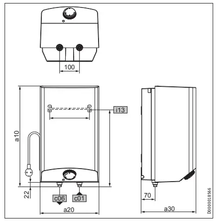
| ESH 10 O-P Plus | ||||
| a10 | Appliance | Height | mm | 506 |
| a20 | Appliance | Width | mm | 296 |
| a30 | Appliance | Depth | mm | 276 |
| c01 | Cold water inlet | Male thread | / | G 1/2 |
| c06 | DHW outlet | Male thread | / | G 1/2 |
| i13 | Wall mounting bracket | Height | mm | 386 |
| Horizontal hole spacing | mm | 200 | ||
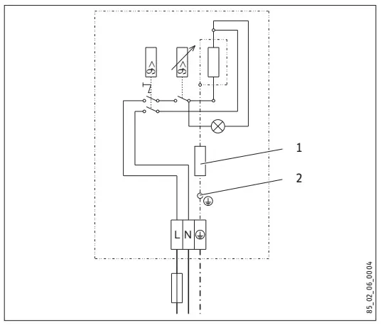
Wiring diagram
1/N/PE ~ 230 V
Heat-up diagram
The heat-up period depends on the degree of scaling and residual heat. For the heat-up time for a cold water supply at 10 °C and a maximum temperature setting, see the diagram.
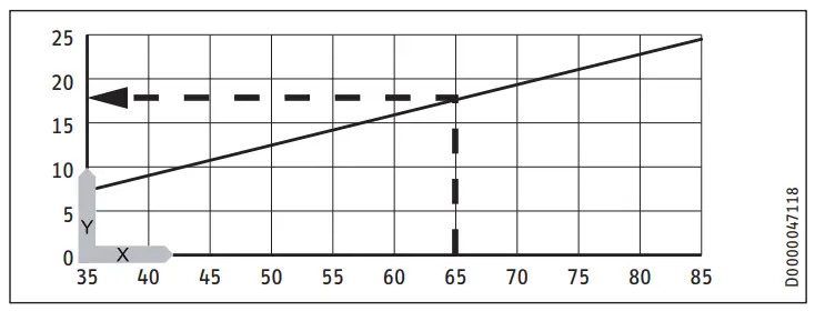
x Temperature in °C
y Duration in min
Example:
Temperature setting = 65 °C
Heat-up time = approx. 18 minutes
Country-specific approvals and certifications
See the type plate for test symbols.
Extreme operating and fault conditions
In the case of faults, a peak temperature up to 105 °C may briefly occur in the system.
Energy consumption data
Product datasheet: Conventional water heaters to regulation (EU) no. 812/2013 and 814/2013
| ESH 10 U-P Plus | ESH 10 O-P Plus | ||
| 201397 | 201398 | ||
| Manufacturer | STIEBEL ELTRON | STIEBEL ELTRON | |
| Load profile | XXS | XXS | |
| Energy efficiency class | A | A | |
| Energy conversion efficiency | % | 36 | 37 |
| Annual power consumption | kWh | 507 | 498 |
| Default temperature setting | °C | 55 | 55 |
| Sound power level | dB(A) | 15 | 15 |
| Daily power consumption | kWh | 2.370 | 2.320 |
Data table
| / | / | ESH 10 U-P Plus 201397 | ESH 10 O-P Plus 201398 | ||||
| Hydraulic data | |||||||
| Rated capacity | l | 10 | 10 | ||||
| Mixed water volume at 40 °C | l | 18 | 18 | ||||
| Electrical detail | |||||||
| Rated voltage | V | 220 | 230 | 240 | 220 | 230 | 240 |
| Rated output | kW | 1.8 | 2.0
| 2.2 | 1.8 | 2.0 | 2.2 |
| Rated current | A | 8.3 | 8.7 | 9.1 | 8.3 | 8.7 | 9.1 |
| Fuse protection | A | 10 | 10 | 10 | 10 | 10 | 10 |
| Phases | 1/N/PE | 1/N/PE | |||||
| Frequency | Hz | 50/60 | 50/60 | ||||
| Application limits | |||||||
| Available temperature range | °C | 35-82 | 35-82 | ||||
| Max. permissible pressure | MPa | 0.6 | 0.6 | ||||
| Max. throughput | l/min | 10 | 10 | ||||
| Energy data | |||||||
| Standby energy consumption/24 h at 65 °C | kWh | 0.36 | 0.34 | ||||
| Energy efficiency class | / | A | A | ||||
| Versions | |||||||
| IP-Rating | / | IP24 D | IP24 D | ||||
| Undersink installation | / | X | |||||
| Oversink installation | / | X | |||||
| Type | / | sealed | sealed | ||||
| Material, internal cylinder | / | Steel, enamelled | Steel, enamelled | ||||
| Thermal insulation material | / | EPS | EPS | ||||
| Casing material | / | PS | PS | ||||
| Colour | / | white | White | ||||
| Connections | |||||||
| Water connection | / | G 3/8 A | G 1/2 A | ||||
| Dimensions | |||||||
| Height | mm | 506 | 506 | ||||
| Width | mm | 296 | 296 | ||||
| Depth | Mm | 276 | 276 | ||||
| Length of connecting cable | mm | 950 | 950 | ||||
| Weight | |||||||
| Weight | kg | 8 | 8 | ||||
Guarantee
The guarantee conditions of our German companies do not apply to appliances acquired outside of Germany. In countries where our subsidiaries sell our products a guarantee can only be issued by those subsidiaries. Such guarantee is only granted if the subsidiary has issued its own terms of guarantee. No other guarantee will be granted.
We shall not provide any guarantee for appliances acquired in countries where we have no subsidiary to sell our products. This will not affect warranties issued by any importers.
Environment and recycling
We would ask you to help protect the environment. After use, dispose of the various materials in accordance with national regulations.
Customer Service
Deutschland
STIEBEL ELTRON GmbH & Co. KG
Dr.-Stiebel-Straße 33 | 37603 Holzminden
Tel. 05531 702-0 | Fax 05531 702-480
[email protected]
www.stiebel-eltron.de
Australia
STIEBEL ELTRON Australia Pty. Ltd.
294 Salmon Street | Port Melbourne VIC 3207
Tel. 03 9645-1833 | Fax 03 9644-5091
[email protected]
www.stiebel-eltron.com.au
Austria
STIEBEL ELTRON Ges.m.b.H.
Gewerbegebiet Neubau-Nord
Margaritenstraße 4 A | 4063 Hörsching
Tel. 07221 74600-0 | Fax 07221 74600-42
[email protected]
www.stiebel-eltron.at
Belgium
STIEBEL ELTRON bvba/sprl
‘t Hofveld 6 – D1 | 1702 Groot-Bijgaarden
Tel. 02 42322-22 | Fax 02 42322-12
[email protected]
www.stiebel-eltron.be
China
STIEBEL ELTRON (Tianjin) Electric Appliance
Co., Ltd.
Plant C3, XEDA International Industry City
Xiqing Economic Development Area
300085 Tianjin
Tel. 022 8396 2077 | Fax 022 8396 2075
[email protected]
www.stiebeleltron.cn
Czech Republic
STIEBEL ELTRON spol. s r.o.
Dopraváků 749/3 | 184 00 Praha 8
Tel. 251116-111 | Fax 235512-122
[email protected]
www.stiebel-eltron.cz
Finland
STIEBEL ELTRON OY
Kapinakuja 1 | 04600 Mäntsälä
Tel. 020 720-9988
[email protected]
www.stiebel-eltron.fi
France
STIEBEL ELTRON SAS
7-9, rue des Selliers
B.P 85107 | 57073 Metz-Cédex 3
Tel. 0387 7438-88 | Fax 0387 7468-26
[email protected]
www.stiebel-eltron.fr
Hungary
STIEBEL ELTRON Kft.
Gyár u. 2 | 2040 Budaörs
Tel. 01 250-6055 | Fax 01 368-8097
[email protected]
www.stiebel-eltron.hu
Japan
NIHON STIEBEL Co. Ltd.
Kowa Kawasaki Nishiguchi Building 8F
66-2 Horikawa-Cho
Saiwai-Ku | 212-0013 Kawasaki
Tel. 044 540-3200 | Fax 044 540-3210
[email protected]
www.nihonstiebel.co.jp
Netherlands
STIEBEL ELTRON Nederland B.V.
Daviottenweg 36 | 5222 BH ‘s-Hertogenbosch
Tel. 073 623-0000 | Fax 073 623-1141
[email protected]
www.stiebel-eltron.nl
Poland
STIEBEL ELTRON Polska Sp. z O.O.
ul. Działkowa 2 | 02-234 Warszawa
Tel. 022 60920-30 | Fax 022 60920-29
[email protected]
www.stiebel-eltron.pl
Russia
STIEBEL ELTRON LLC RUSSIA
Urzhumskaya street 4,
building 2 | 129343 Moscow
Tel. 0495 7753889 | Fax 0495 7753887
[email protected]
www.stiebel-eltron.ru
Slovakia
STIEBEL ELTRON Slovakia, s.r.o.
Hlavná 1 | 058 01 Poprad
Tel. 052 7127-125 | Fax 052 7127-148
[email protected]
www.stiebel-eltron.sk
Switzerland
STIEBEL ELTRON AG
Industrie West
Gass 8 | 5242 Lupfig
Tel. 056 4640-500 | Fax 056 4640-501
[email protected]
www.stiebel-eltron.ch
Thailand
STIEBEL ELTRON Asia Ltd.
469 Moo 2 Tambol Klong-Jik
Amphur Bangpa-In | 13160 Ayutthaya
Tel. 035 220088 | Fax 035 221188
[email protected]
www.stiebeleltronasia.com
United Kingdom and Ireland
STIEBEL ELTRON UK Ltd.
Unit 12 Stadium Court
Stadium Road | CH62 3RP Bromborough
Tel. 0151 346-2300 | Fax 0151 334-2913
[email protected]
www.stiebel-eltron.co.uk
United States of America
STIEBEL ELTRON, Inc.
17 West Street | 01088 West Hatfield MA
Tel. 0413 247-3380 | Fax 0413 247-3369
[email protected]
www.stiebel-eltron-usa.com


