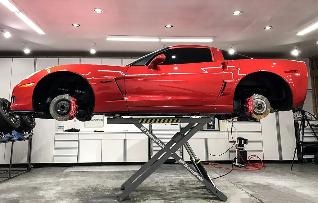

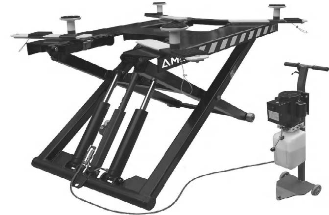
AMGO MR06 Mid-Rise Scissor Portable Lift
PRODUCT FEATURES AND SPECIFICATIONS
PORTABLE MID-RISED MODEL MR06
● Manual safety lock: mechanical safety locks release, No need air source.
● High speed: From 0-1090mm (43”) in just 21 seconds
● Portable design: It is easy to move the whole lift with the power unit stand
● Adjustable rubber pad included
MODEL MR06 SPECIFICATIONS
| Model | Lifting Capacity | Raised Height | Lifting Time | Overall Length | Overall Width | Lowered Height | Motor |
| MR06 | 6,000 lbs | 43” | 26S | 74 1/4’’ | 66 1/4” | 5” | 2.0HP |
INSTALLATION REQUIREMENT
A. TOOLS REQUIRED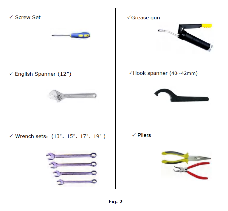
B. POWER SUPPLY
The electrical source must be 2.2kw minimum. The source cable size must be 2.5mm² and in good condition of contacting with floor.
INSTALLATION STEPS
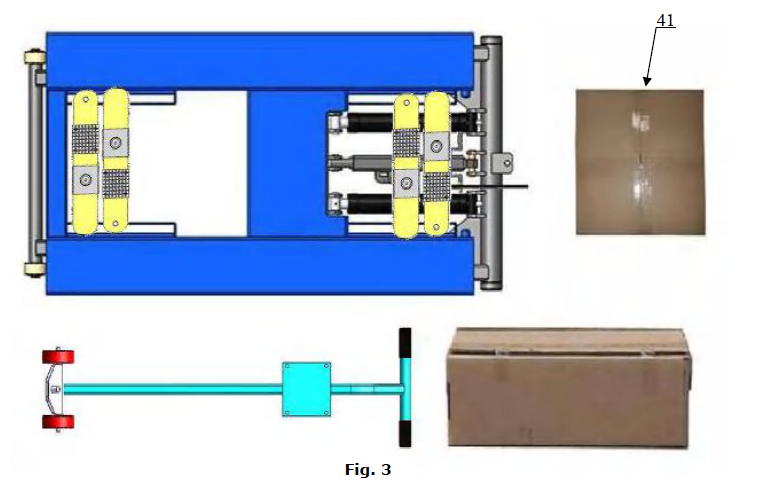
Check the parts before assembly, make sure all the parts are completed.
- Packaged lift, Parts box, Power Unit and Power Unit Stand. Move the parts aside, open the outer packing and check the parts according to the shipment parts list (See Fig. 3).

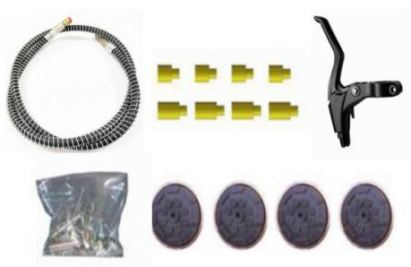
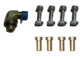
- Open the parts box, check the parts according to the part list (See Fig. 4).

- Check the parts of the parts bag according to the parts bag list (See Fig. 5).

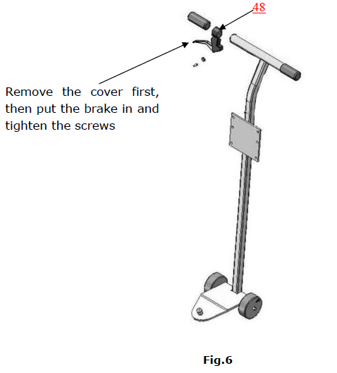
Install the brake
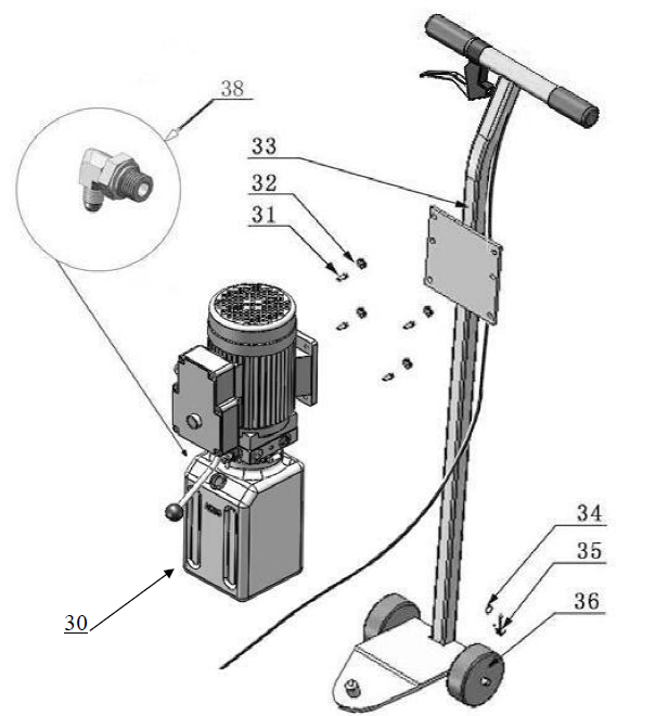
 Then Install power unit and fitting (See Fig. 7)
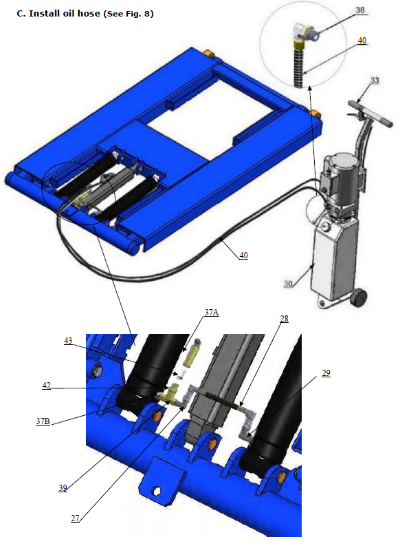
Install oil hose (See Fig. 8)
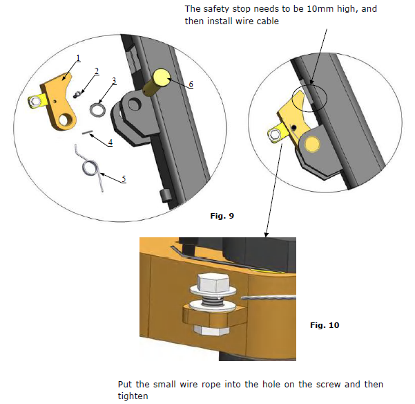
Install safety device and cable
- Put the safety device parts as Fig.9

| Item | Part# | Description | MR06 | Item | Part# | Description | MR06 | |
| QTY | QTY | |||||||
| 1 | 11640150 | Safety stop | 1 | 4 | 1061K104 | Split pinφ3*30 | 1 | |
| 2 | 81400438 | Hex bolt M5*10 | 1 | 5 | 10640155 | Springφ23*φ27*2 | 1 | |
| 3 | 10510053 | Washer | 1 | 6 | 11640154 | Safety pin | 1 |
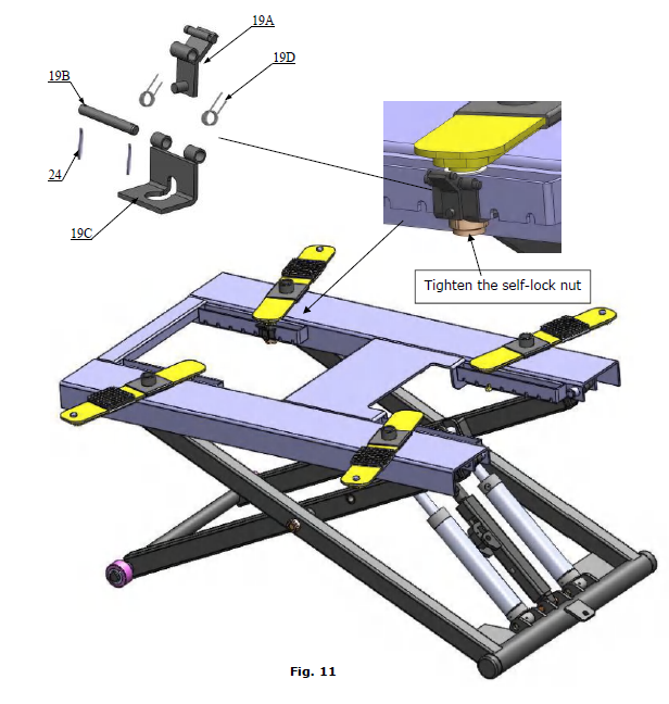
Install supporting arm
- Raise the lift up to 39 3/8’’ and lock the safety device, then tighten the self-lock nut.(See Fig. 11) Note:Make sure the supporting arms can move left/right

Install electric system
Connect the power source on the data plate of Motor
Note:
1. For the safety of operators, the power wiring must be contacted the floor well.
2. Pay attention to the direction of rotations when using three phase motors.
Single phase motor (See Fig. 12)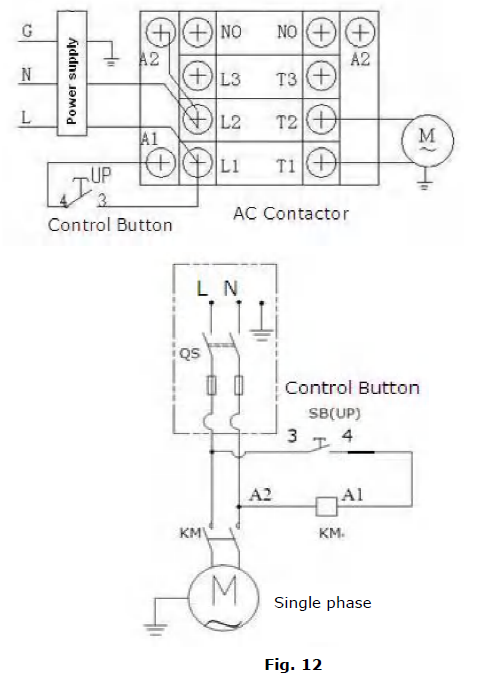
1. Connecting the two power supply lines (fire wire L and zero wire N) to terminals of AC contactor marked L1, L2 respectively.
2. Connecting the two motor wires to terminals of AC contactor marked T1, T2.
3. Connecting L2 to A2 of AC contactor.
4. Two wires of control button connected with terminals of AC contactor marked A1, L1.
EXPLODED VIEW
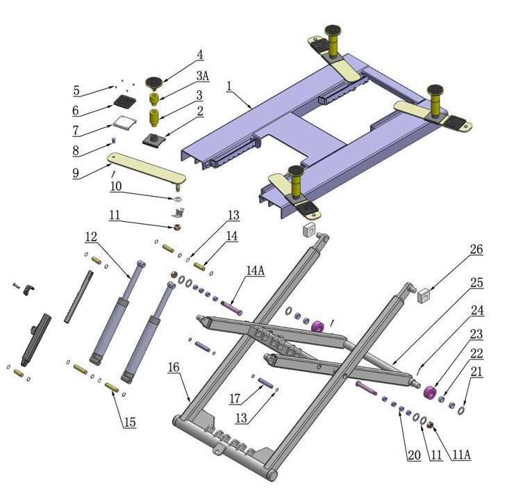
PARTS LIST FOR MODEL MR06
| Item | Part# | Description | QTY. | Note | |
| 1 | 11640001 | Platform | 1 | ||
| 2 | 11640002A | Stackable Adapter Bracket | 4 | ||
| 3 | 11209052B | Stackable Adapter (2.5”) | 4 | ||
| 3A | 11209051B | Stackable Adapter (1.5”) | 4 | ||
| 4 | 10201046A | Rubber Pad Assy. | 4 | ||
| 4A | 10420138 | Socket bolt | 4 | ||
| 4B | 10209134 | Rubber pad | 4 | ||
| 4C | 11680030C | Rubber Pad Frame | 4 | ||
| 5 | 10209009 | Cup Head Bolt | 16 | ||
| 6 | 10680004 | Rubber Pad | 4 | ||
| 7 | 10640003 | Supporting pad | 4 | ||
| 8 | 11640023A | Limit pin | 4 | ||
| 9 | 11640004 | Supporting arm | 4 | ||
| 10 | 10640005 | Washer | 10 | ||
| 11 | 10640109 | Washer | 4 | ||
| 11A | 10620022 | Self-locking Nut | 6 | ||
| 12 | 10640116 | Cylinder | 2 | ||
| 13 | 10206032 | Snap Ring | 12 | ||
| 14 | 11640057 | Pin for Cylinder Connecting | 2 | ||
| 14A | 11640012 | Pin | 2 | ||
| 15 | 11640006A | Pin for Cylinder | 2 | ||
| 16 | 11640017B | Outer Scissor | 1 | ||
| 17 | 11640009 | Inner Scissor Pin | 2 | ||
| 18 | 11640130 | Safety Bar Set | 2 | ||
|
19 | 19A | 11640134 | Slide limit block | 4 | |
| 19B | 11640135 | Slide stop | 4 | ||
| 19C | 11640136 | Safety Pin | 4 | ||
| 19D | 10640127 | Spring | 8 | ||
| 20 | 10203004A | Bronze Bush | 8 | ||
| 21 | 10420023A | Washer | 2 | ||
| 22 | 10420132A | Bronze Bush | 4 | ||
| 23 | 11640022 | Roller | 2 | ||
| 24 | 10630107 | Split Pin | 10 | ||
| 25 | 11640016B | Inner Scissor | 1 | ||
| 26 | 10610003A | Slider | 2 | ||
| 27 | 1061K107 | Straight Fitting | 1 | ||
| 28 | 10640114 | Oil Hose | 1 | ||
| Item | Part# | Description | QTY. | Note | |
| 29 | 10420097 | Straight Fitting | 2 | ||
| 30 | 81513006/81513007 | Manual Power Unit | 1 | ||
| 31 | 10209003 | Hex Bolt | 4 | ||
| 32 | 10209005 | Self-locking Nut | 4 | ||
| 33 | 10640138 | Power Unit Stand | 1 | ||
| 34 | 10206006 | Washer | 2 | ||
| 35 | 10201005 | Split Pin | 2 | ||
| 36 | 10640023 | Roller | 2 | ||
| 37A | 10201020 | 900 Fitting | 1 | ||
| 37B | 10209119 | compensation valve | 1 | ||
| 38 | 10209060 | Straight Fitting for Power Unit | 1 | ||
| 39 | 10206062 | T Fitting | 1 | ||
| 40 | 1003015002 | Oil Hose Assy | 1 | ||
| 41 | 10640500A | Parts Box | 1 | ||
| 42 | 10420244 | Straight fitting | 1 | ||
| 43 | 10420245 | Straight fitting | 1 | ||
| 44 | 11640150 | Safety block | 1 | ||
| 45 | 11640131 | Safety block pin | 1 | ||
| 46 | 11640153 | Self-lock supporting tube | 1 | ||
| 47 | 11640152 | Self-lock supporting pin | 1 | ||
| 48 | 10640115 | brake | 1 | ||
CYLINDER (10640116)
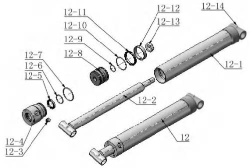
| PARTS FOR HYDRAULIC CYLINDER | ||||
| Item | Part# | Description | QTY. | Note |
| 12-1 | 11640657 | Bore Weldment | 2 | |
| 12-2 | 11640031A | Piston Rod | 2 | |
| 12-3 | 10201034 | Bleeding Plug | 2 | |
| 12-4 | 11203083 | Head Cap | 2 | |
| 12-5 | 10209078 | Dust Ring | 2 | |
| 12-6 | 10201032 | O – Ring | 2 | |
| 12-7 | 10203084 | O – Ring | 2 | |
| 12-8 | 11203079 | Piston | 2 | |
| 12-9 | 10206069 | O-Ring | 2 | |
| 12-10 | 10203082 | O-Ring | 2 | |
| 12-11 | 10410087 | Y-Ring | 2 | |
| 12-12 | 10410086 | Support Ring | 2 | |
| 12-13 | 10206071 | Nut | 2 | |
| 12-14 | 10620064 | Greasing Fitting | 4 | |
MANUAL POWER UNIT (071104)
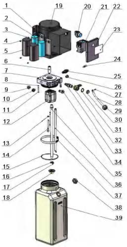
Parts for Manual power unit
| Item | Part# | Description | QTY. | Note |
| 1 | 81400180 | Rubber pad | 2 | |
| 2 | 81400130 | Start capacitor | 1 | |
| 3 | 81400088 | Run capacitor | 1 | |
| 4 | 10420148 | Cup head bolt with washer | 4 | |
| 5 | 81400066 | Cover for capacitor | 2 | |
| 6 | 81400363 | Motor connecting shaft | 1 | |
| 7 | 090106 | Manifold block | 1 | |
| 8 | 10209149 | Lock washer | 4 | |
| 9 | 81400276 | Iron plug | 1 | |
| 10 | 81400259 | Red rubber plug | 1 | |
| 11 | 85090142 | Socket bolt | 4 | |
| 12 | 81400280 | Gear pump | 1 | |
| 13 | 10209034 | Washer | 2 | |
| 14 | 81400295 | Socket bolt | 2 | |
| 15 | 81400365 | O-ring | 1 | |
| 16 | 10209152 | Belt | 1 | |
| 17 | 85090167 | Magnet | 1 | |
| 18 | 81400290 | Filter mesh | 1 | |
| 19 | 81400413 | Motor | 1 | |
| 20 | 10420070 | Button switch | 1 | |
| 21 | 41030055 | AC contactor | 1 | |
| 22 | 81400287 | Cover of motor terminal box | 1 | |
| 23 | 71111174 | AMGO label | 1 | |
| 24 | 81400560 | Throttle valve | 1 | |
| 25 | 81400266 | Release valve | 1 | |
| 26 | 81400284 | Iron plug | 1 | |
| 27 | 10720118 | Hair pin | 1 | |
| 28 | 81400451 | Handle for release valve | 1 | |
| 29 | 10209020 | Plastic ball for arm lock | 1 | |
| 30 | 81400421 | Release valve nut | 1 | |
| 31 | 81400422 | Release valve shim | 1 | |
| 32 | 81400449 | Valve seat(Low) | 1 | |
| 33 | 070001 | Release valve | 1 | |
| 34 | 070002 | Check valve | 1 | |
| 35 | 81400288 | Oil suction pipe | 1 | |
| 36 | 814002889 | Oil return pipe | 1 | |
| 37 | 81400364 | Hose clamp (stainless steel) | 1 | |
| 38 | 81400263 | Oil tank cap | 1 | |
| 39 | 81400320 | Oil tank | 1 |
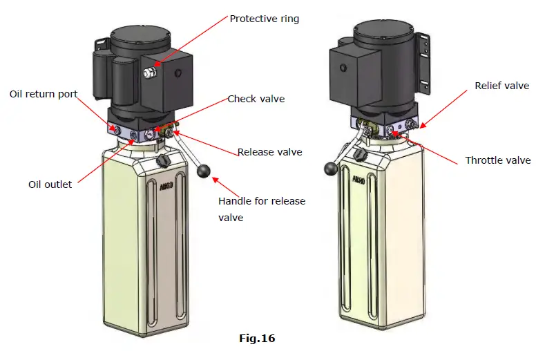
Manual Power unit single phase
OPERATION INSTRUCTIONS
- Install the oil hose between the oil cylinder and power unit, connect with the power supply wire well. The machine can be ready to use.
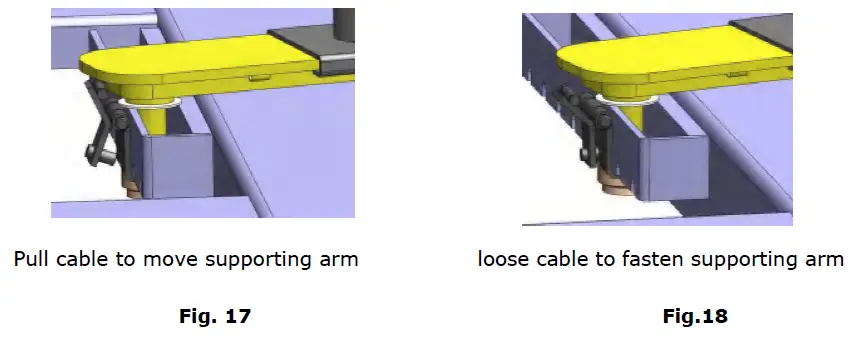
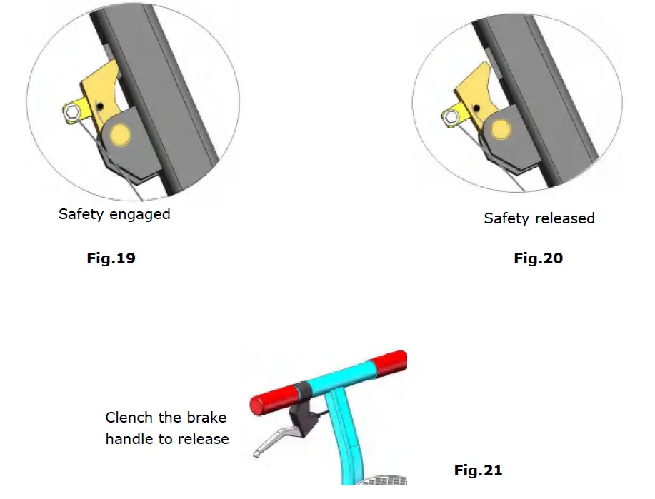
- When lifting a vehicle, be sure the center of gravity of the vehicle must be in the middle of the lift, select the suitable adapters, pull the small cables of the yellow supporting arms to open the lock and move the arms to find the support point. (See Fig.18,19)Make sure the safety lock must be in engaged when lifting (See Fig. 20).
- Lower the lift: Press the button “UP”, until the safety lock is in released position to clench the brake handle (See Fig.21,22), lower the lift by pushing the lowering handle.


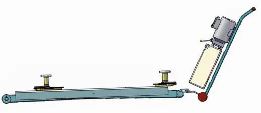
- Move the lift with the power unit stand (See Fig. 22)

MAINTENANCE SCHEDULE
Monthly:
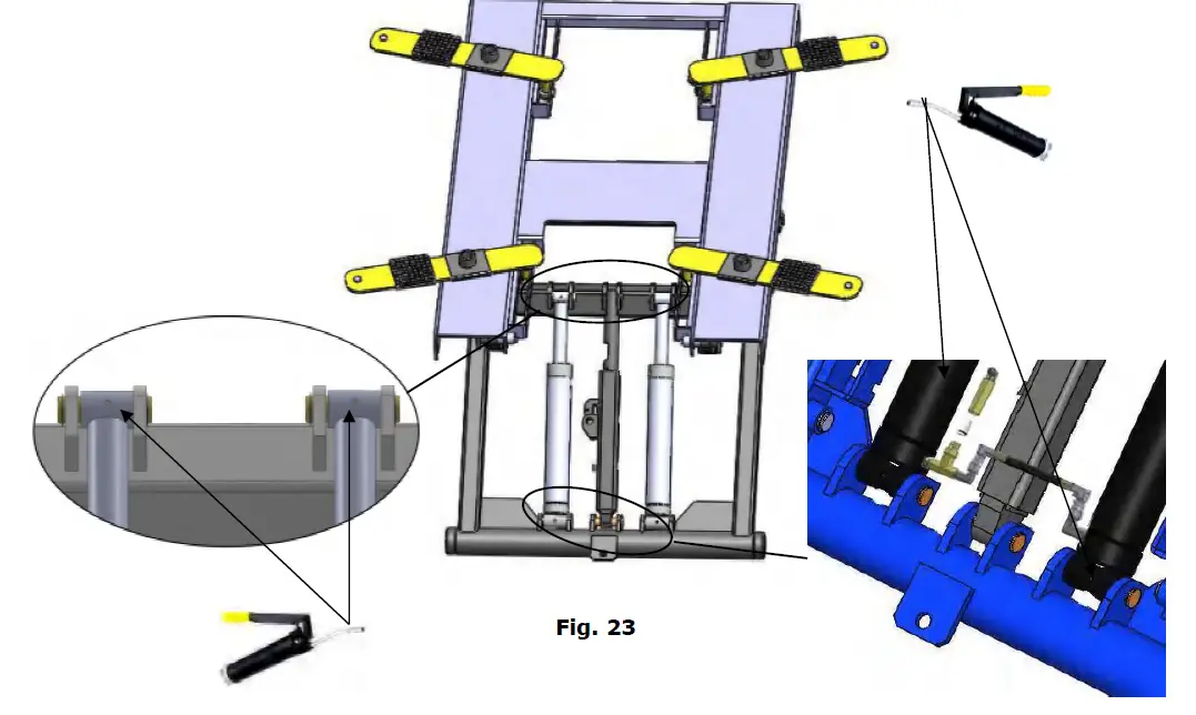
- Lubricate all moving parts with lubricant (See Fig.23).

- Check all connectors, bolts and pins to insure proper mounting.
- Make a visual inspection of all hydraulic hoses/lines for possible wear or leakage.
Every six months:
- Make a visual inspection of all moving parts for possible wear, interference or damage.
- Check all fasteners and re-torque.
TROUBLESHOOTING
| TROUBLE | CAUSE | REMEDY |
|
Motor does not run | 1. Button does not work 2. Wiring connections are not in good condition 3. Motor burned out 4. Safety Switch is damaged 5. AC contactor burned out | 1. Replace button 2. Repair all wiring connections
3. Repair or replace motor 4. Replace the Safety Switch 5. Replace AC Contactor |
|
Motor runs but the lift is not raised | 1. Motor runs in reverse rotation 2. Gear Pump out of operation 3. Release Valve in damage 4. Relief Valve or Check Valve in damage 5. Low oil level 6. Overload lifting or low pressure | 1.Reverse two power wire 2. Repair or replace 3. Repair or replace 4. Repair or replace 5. Fill tank 6.Check load or adjust the pressure |
|
Lift does not stay up | 1. Release Valve out of work 2. Relief Valve or Check Valve leakage 3. Cylinder or Fittings leaks |
Repair or replace |
|
Lift raises slowly | 1. Oil line is jammed 2. Motor running on low voltage 3. Oil mixed with air 4. Gear Pump leaks 5. Overload lifting | 1. Clean the oil line 2. Check Electrical System 3. Fill tank 4. Repair or replace 5. Check load |
|
Lift cannot lower | 1. Safety device are in activated 2. Release Valve in damage 3. Oil system is jammed | 1. Release the safeties 2. Repair or replace 3. Clean the oil system |
Lift disposal.
When the car lift cannot meet the requirements for normal use and needs to be disposed, it should follow local laws and regulations.
AMGO HYDRAULIC CORPORATION
1931 Joe Rogers Blvd, Manning, South Carolina, Zip:29102
Tel: (803) 505-6410
fax: (803) 505-6410
Manual Part No.: 72106408
Revision Date: 2020/07


