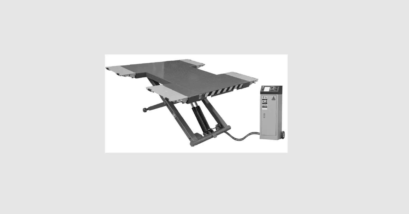
AMGO EM06 Hydrulics Portable Mid Rise Scissor
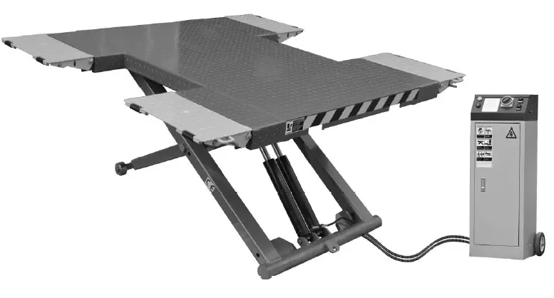
PRODUCT FEATURES AND SPECIFICATIONS
MID-RISED MODEL EM06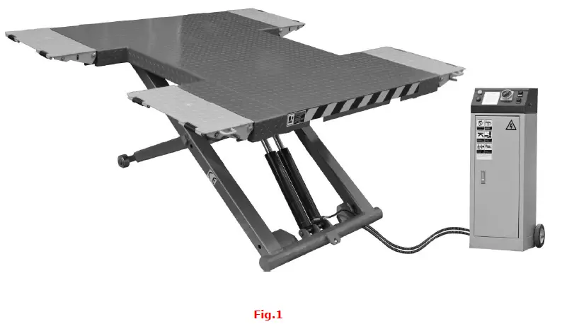
- Low voltage(24V) electric control system, refinement control cabinet.
- Dual oil circuit design and hydraulic self-lock system
- Dual hydraulic cylinders to make the operation more stable.
- Movable drive–in ramps and extended platforms accommodate varying wheelbase vehicles.
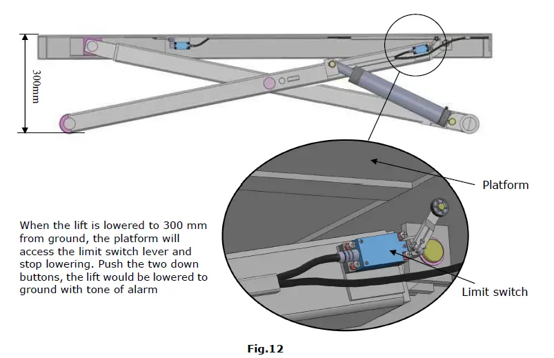
- Stop switch and alarm tone when coming down from 300mm to ground
- Non-skid diamond runway.
MODEL EM06 SPECIFICATIONS
| Model | Lifting Capacity | Lifting Time | Raised Height | Lowered Height | Overall Width | Overall Length | Motor |
| EM06 | 6,000 lbs | 22S | 41 3/4” | 4 1/8” | 80 3/8’” | 80” | 2.0HP |
INSTALLATION REQUIREMENT
TOOLS REQUIREMENT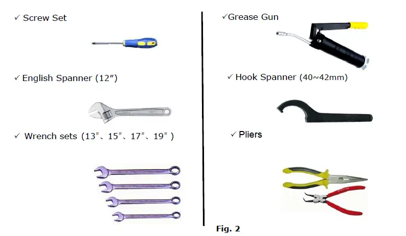
Equipment storage and installation requirements.
The equipment should be stored or installed in a shady, normal temperature, ventilated and dry place.
The equipment should be unload and transfer by forklift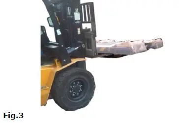
POWER SUPPLY
The electrical source must be 2.0HP minimum. The source cable size must be 2.5mm² and in good condition of contacting with floor.
STEPS OF INSTALLATION
Location of installation
Check the installation location (concrete, layout, space size etc.) is suitable for lift installation (See Fig. 4).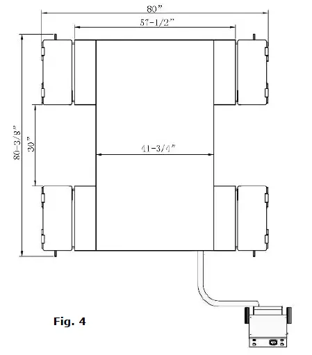
Check the parts before assembly, make sure all the parts are completed.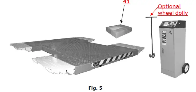
- Packaged lift, Parts box, Control cabinet and the optional wheel dolly. Move the parts aside, open the outer packing and check the parts according to the shipment list (See Fig. 5).
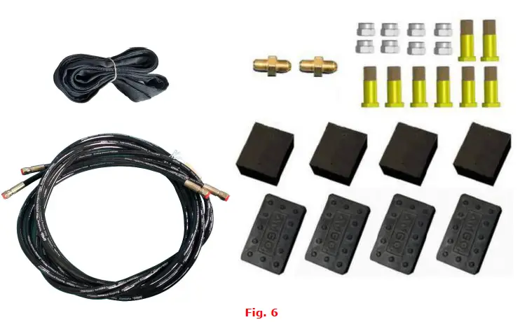
- Open the parts box, check the parts according to the part list (See Fig. 6).
Lay out the lift and control cabinet according to step A and connect oil hoses (See Fig. 7).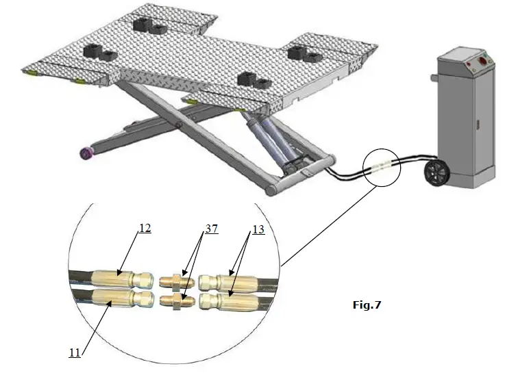
Hydraulic system (See Fig.8)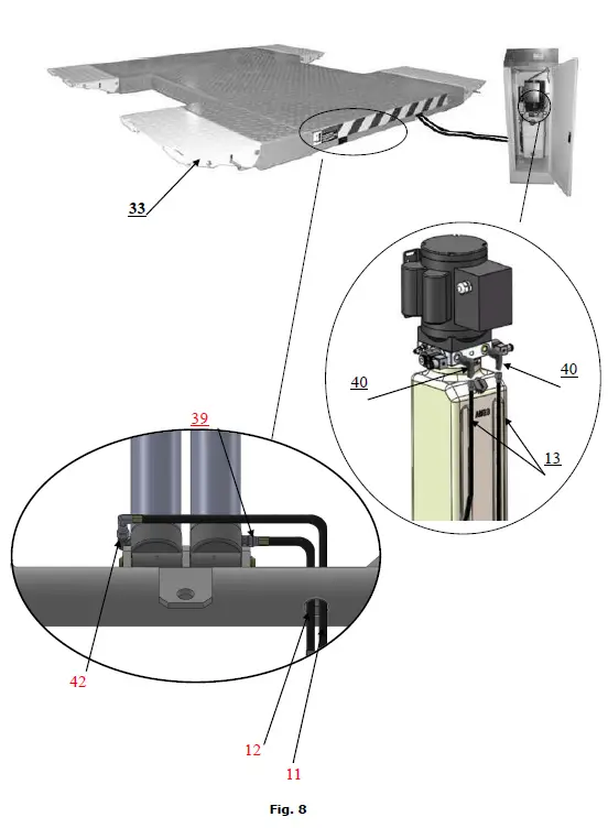
- 220V Circuit connection
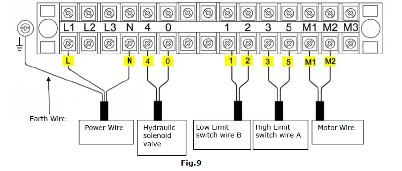
- Connect the power source wire and limit switch according to the Wiring diagram

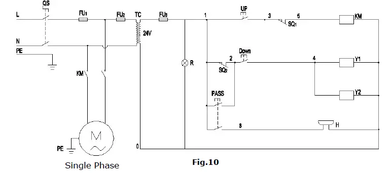
- Circuit Diagram (See Fig.10)

Item Name Code Specification Item Name Code Specification 1 Power switch QS 220V AC 8 Hydraulic solenoid valve Y AC 24V 2 Breaker FU1 2P 9 Push button UP Single 3 Breaker FU2 1P 10 Push button Down Single 4 Breaker FU3 1P 11 Push button Pass Duplex 5 AC contactor KM 24V AC 12 Motor M Single Phase 6 High Limit switch SQ1 10A 13 Transformer TC 24V AC 7 Low Limit switch SQ2 10A 14 Power indicator R 24V AC
- Connect the power source wire and limit switch according to the Wiring diagram
- Electric Component


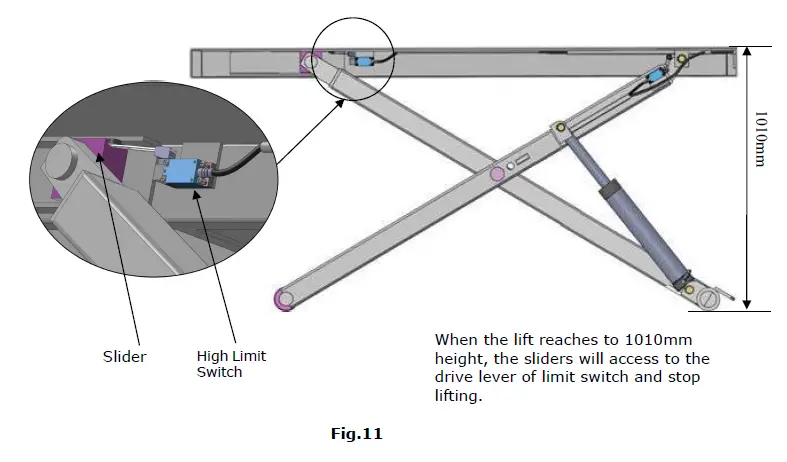
- Higher limit switch illustration (See Fig.11)
- Lower alarm device instruction (See Fig.12)
EXPLODED VIEW
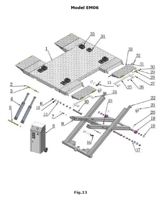
PARTS LIST FOR EM06
| Item | Part# | Description | QTY. | Note |
| 1 | 11650001 | Platform | 1 | |
| 2 | 10206032 | Snap Ring F25 | 12 | |
| 3 | 11640006A | Connecting Shaft for Cylinder | 2 | |
| 4 | 10640116 | Cylinder | 2 | |
| 5 | 11650049 | Cylinder Base Pin | 1 | |
| 6 | 10610019 | Self-locking Nut M30*3.5 | 2 | |
| 6A | 10610108 | Washer Φ44*Φ30.5*2 | 2 | |
| 7 | 11650003 | Inner Scissor Pin | 2 | |
| 8 | 10650048 | Control Cabinet | 1 | |
| 9 | 11640016 | Inner Scissors | 1 | |
| 10 | 11650018 | Scissors Pin | 2 | |
| 11 | 10650050 | Oil hose 1/4²*740mm | 1 | |
| 12 | 1086010280 | Oil hose 1/4²*500mm | 1 | |
| 13 | 1003095002 | Oil hose 1/4²*3000mm | 2 | |
| 14 | 10650029 | Lower Limit Switch Assy. | 1 | |
| 15 | 10650028 | Higher Limit Switch Assy. | 1 | |
| 16 | 10650026 | Washer Φ60*Φ36*3 | 2 | |
| 17 | 10420132A | Bronze Bush for Pulley F41.3*F35.1*20 | 12 | |
| 18 | 10420023A | Washer F36*F65*3 | 2 | |
| 19 | 11640022 | Roller | 2 | |
| 20 | 10201005 | Split Pin F4*50 | 2 | |
| 21 | 10610003A | Slider Block | 2 | |
| 22 | 11640017A | Outer Scissor | 1 | |
| 23 | 10420156 | Protecting Rubber Ring F24 | 5 | |
| 24 | 11620130 | Support Bracket(right) | 2 | |
| 26 | 11620123 | Bracket Shaft φ16*90 | 8 | |
| 27 | 10420037 | Snap Ring φ16 | 16 | |
| 28 | 10610667 | Roller for Drive-in Ramp | 8 | |
| 29 | 11620043 | Roller shaft for drive in ramp | 8 | |
| 30 | 10209010 | Snap Ring φ10 | 16 | |
| 31 | 10650024 | Self-locking Nut M16 | 8 | |
| 32 | 11620124 | Pin for Drive-in Ramp | 8 | |
| 33 | 11620128 | Drive-in Ramp | 4 | |
| 34 | 10620034 | Rubber Pad 120*100*38 | 4 | |
| 35 | 10610070 | Rubber Pad 120*100*70 | 4 | |
| 36 | 10650008 | Oil Hose sleeve F25*3000 | 1 | |
| 37 | 10620079 | Straight Fitting 1/4JIC(M) *1/4JIC(M) | 2 |
| Item | Part# | Description | QTY. | Note |
| 38 | 10650010 | Wheel dolly assy.(optional) | 1 | |
| 39 | 10209064 | Straight Fitting for cylinder 1/4JIC(M)*1/4NPT(M) | 1 | |
| 40 | 10209060 | 90° Fitting for Power Unit | 2 | |
| 41 | 10650501 | Parts Box | 1 | |
| 42 | 10420097 | 90° Fitting 1/4NPT(M)*1/4JIC(M) | 1 | |
| 43 | 10201108 | Fitting | 1 | |
| 200 | 071203 | Power Unit | 1 |
CONTROL CABINET
Part #:10650048(Single Phase)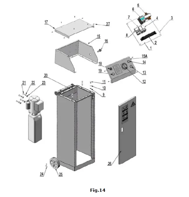
| Parts for Control Cabinet | ||||
| Item | Part# | Description | QTY. | Note |
| 1 | 11650651 | Terminal Blocks | 1 | |
| 2 | 10620082 | Panel for Installing Element | 1 | |
| 3 | 1061K052 | Cup head screw | 15 | |
| 4 | 10202049 | Breaker 1P | 1 | |
| 5 | 10420134 | 24V AC Contractor (KM) | 1 | |
| 6 | 10420084A | 24V Transformer (TC) | 1 | |
| 7 | 10202049 | Breaker 1P | 1 | |
| 8 | 10202046 | Fuse 2P (Single Phase only) | 1 | |
| 9 | 10217011 | Hex nut M6 | 4 | |
| 10 | 10420045 | φ6Washer | 4 | |
| 11 | 1061K108 | Hex bolt M6*12 | 4 | |
| 12 | 41010217 | Power Switch (QS) | 1 | |
| 13 | 10201094 | Indicator lamp | 1 | |
| 14 | 10420070 | Button (UP) | 1 | |
| 15 | 11650660 | Upper box | 1 | |
| 15A | 11650654 | Control Panel | 1 | |
| 16 | 10420142 | Button (PASS) | 1 | |
| 17 | 11650653 | Cabinet cover | 1 | |
| 18 | 10420143 | Buzzer | 1 | |
| 19 | 10420070 | Button (DOWN) | 1 | |
| 20 | 11650665 | Cabinet box | 1 | |
| 21 | 1061K050 | Hex Bolt M8*30 | 4 | |
| 22 | 10209033 | φ8Washer | 4 | |
| 23 | 10209005 | Self-locking nut M8 | 4 | |
| 24 | 1061K104 | Split pin 3*30 | 2 | |
| 25 | 1061K102 | Roller φ150*φ12*3 | 2 | |
| 26 | 11650666 | Cabinet door | 1 | |
| 27 | 10420153 | Cup head screw M6*20 | 12 | |
WHEEL DOLLY (Optional) 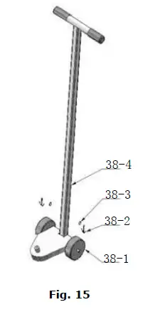
CYLINDER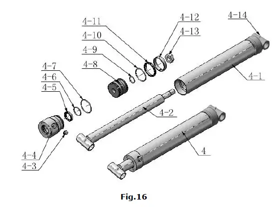
| PARTS FOR CYLINDER | ||||
| Item | Part# | Description | QTY. | Note |
| 4-1 | 11640657 | Bore Weldment | 2 | |
| 4-2 | 11640031A | Piston Rod | 2 | |
| 4-3 | 10201034 | Bleeding Plug | 2 | |
| 4-4 | 11203083 | Head cap | 2 | |
| 4-5 | 10209078 | Dust ring | 2 | |
| 4-6 | 10201032 | O-Ring inside head cap | 2 | |
| 4-7 | 10203084 | O-Ring outside head cap | 2 | |
| 4-8 | 11203079 | Piston | 2 | |
| 4-9 | 10206069 | Small O-Ring for Piston | 2 | |
| 4-10 | 10203082 | O-Ring outside piston | 2 | |
| 4-11 | 10410087 | Y-Ring OSI | 2 | |
| 4-12 | 10410086 | Support Ring | 2 | |
| 4-13 | 10206071 | Nut | 2 | |
| 4-14 | 10620064 | Greasing Fitting | 4 | |
| PARTS FOR OPTIONAL WHEEL DOLLY | ||||
| 38-1 | 1003275021 | White wheel | 2 | |
| 38-2 | 10420046 | Split Pin φ3*20 | 2 | |
| 38-3 | 10206006 | Washer φ12 | 2 | |
| 38-4 | 11650012 | Power unit Stand | 1 | |
ELECTRIC POWER UNIT (071203)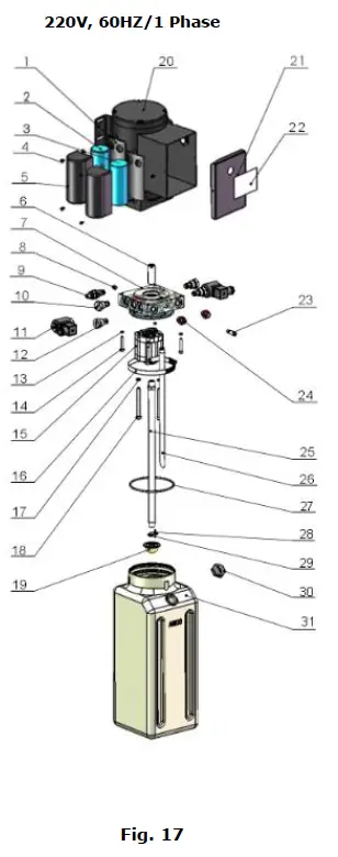
| Parts for Electric Power Unit 220V/60Hz/1 Phase | ||||
| 1 | 81400180 | Rubber pad | 2 | |
| 2 | 81400250 | Start capacitor | 1 | |
| 3 | 81400200 | Running capacitor | 1 | |
| 4 | 10420148 | Cap head screw with washer | 6 | |
| 5 | 81400066 | Cover of capacitor | 2 | |
| 6 | 81400363 | Motor connecting shaft | 1 | |
| 7 | 80101015 | Manifold block | 1 | |
| 8 | 81400333 | Socket plug | 4 | |
| 9 | 81400266 | Relief valve | 1 | |
| 10 | 81400566 | Check valve | 2 | |
| 11 | 81400420 | Solenoid valve coil | 2 | |
| 12 | 81400423 | Electric pressure relief valve | 2 | |
| 13 | 10209149 | Washer φ6 | 4 | |
| 14 | 85090142 | Socket bolt | 4 | |
| 15 | 81400280 | Gear pump | 1 | |
| 16 | 81400364 | Clamp (stainless steel) | 1 | |
| 17 | 10209034 | Lock washer φ8 | 2 | |
| 18 | 81400295 | Socket bolt | 2 | |
| 19 | 81400290 | Filter | 1 | |
| 20 | 81400413 | Motor | 1 | |
| 21 | 81400287 | Cover of Motor Terminal Box | 1 | |
| 22 | 71111231 | AMGO Label | 1 | |
| 23 | 81400560 | Throttle valve | 1 | |
| 24 | 81400259 | Red plastic plug | 2 | |
| 25 | 81400288 | Oil Inlet Pipe | 1 | |
| 26 | 81400289 | Oil Return Pipe | 1 | |
| 27 | 81400365 | O-ring | 1 | |
| 28 | 10209152 | Ties | 1 | |
| 29 | 85090167 | Magnet | 1 | |
| 30 | 81400263 | Oil tank Cap | 1 | |
| 31 | 81400275 | Oil tank | 1 | |
AMGO Electric power unit valve illustration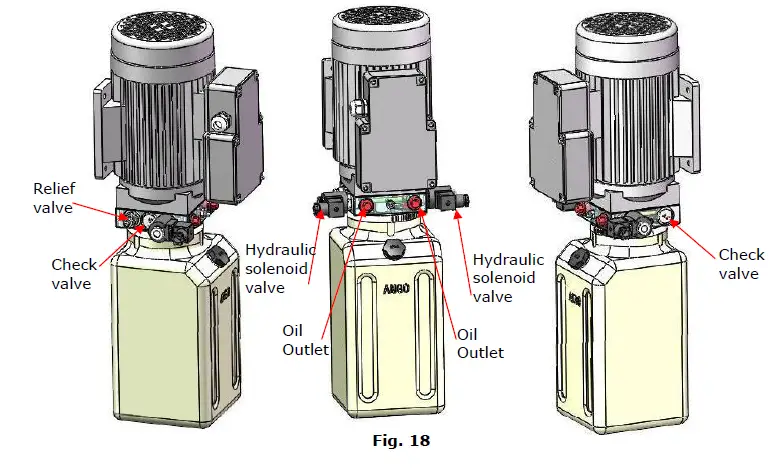
OPERATION INSTRUCTIONS
- Install the oil hoses between oil cylinders and power unit, connect the power wire. The machine can be ready to use.
- Drive the vehicle on the platform, select the suitable rubber pad.
- To lower lift Clean the obstacles around and under the lift, ensure people in safety area. Press the DOWN button to lower the lift.
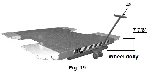
- Move the lift: Raise or lower the lift from 200mm to the ground, use the optional wheel dolly to move (See Fig.19)
MAINTENANCE SCHEDULE
Monthly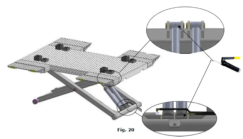
- Lubricate all moving parts with lubricant (See Fig.20)
- Check all connectors, bolts and pins to insure proper mounting.
- Make a visual inspection of all hydraulic hoses/lines for possible wear or leakage.
Every six months
- Make a visual inspection of all moving parts for possible wear, interference or damage.
- Check all fastener and re-torque.
Oil cylinder maintenance:
In order to extend the service life of the oil cylinder, please operate according to the following requirements.
- Recommend to use N46 anti-wear hydraulic oil.
- The hydraulic oil of the lifts should be replaced regularly during using. Replace the hydraulic oil 3 months after the first installation, Replace the hydraulic oil once a year afterwards.
- Make at least one full trip raising and lowering per day. For exhausting the air from the system, which could effectively avoid the corrosion of the cylinder and damage to the seals caused by presence of air or water in the system.
- Protect the outer surface of the oil cylinder’s piston rod from bumping and scratching, and timely clean up the debris on the oil cylinder dust-ring and the piston rod.
TROUBLESHOOTING
| TROUBLE | CAUSE | REMEDY |
|
Motor does not run | 1. Button does not work 2. Wiring connections are not in good condition 3. Motor burned out 4. Safety Switch is damaged 5. AC contactor burned out | 1. Replace button 2. Repair all wiring connections
3. Repair or replace motor 4. Replace the Safety Switch 5. Replace AC Contactor |
|
Motor runs but the lift is not raised | 1. Motor runs in reverse rotation 2. Gear Pump out of operation 3. Relief Valve or Check Valve in damage 4. Low oil level 5. Overload lifting or low pressure | 1. Reverse two power wire 2. Repair or replace 3. Repair or replace 4. Fill tank 5. Check load or adjust the pressure |
|
Lift does not stay up | 1. Release Valve out of work 2. Relief Valve or Check Valve leakage 3. Cylinder or Fittings leaks |
Repair or replace |
|
Lift raises slowly | 1. Oil line is jammed 2. Motor running on low voltage 3. Oil mixed with air 4. Gear Pump leaks 5. Overload lifting | 1. Clean the oil line 2. Check Electrical System 3. Fill tank 4. Repair or replace 5. Check load |
|
Lift cannot lower | 1. Safety device are in activated 2. Release Valve in damage 3. Oil system is jammed | 1. Release the safeties 2. Repair or replace 3. Clean the oil system |
Lift disposal
When the car lift cannot meet the requirements for normal use and needs to be disposed, it should follow local laws and regulations.
AMGO HYDRAULIC CORPORATION
1931 Jo Rogers Blvd, Manning, South Carolina, USA
Tel: (803) 505-6410
Fax: (803) 505-6410
Manual Part No.: 72215403
Revision Date: 2022/03


