
AMGO Portable Low-rised Scissors Lift LR06
PRODUCT FEATURES AND SPECIFICATIONS
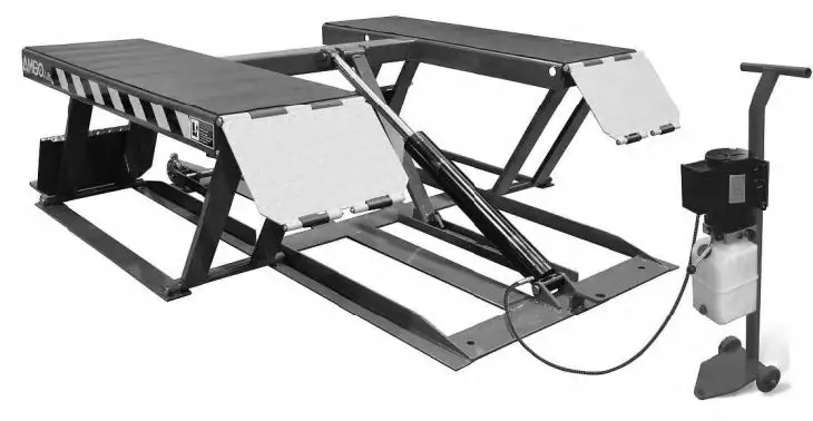
PORTABLE LOW-RISED MODEL LR06
- Self-locking safety device: 3 stage safety lock, mechanical lock, automatic release.
- Portable unit is easy to move with the power unit stand
- High speed: From 0-23 5/8” just 21 seconds
- Standard rubber pads included
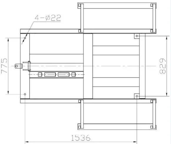
MODEL LR06 SPECIFICATIONS
| Model | Lifting Capacity | Raised Height | Lifting Time | Overall Length | Overall Width | Lowered Height | Runway Width | Runway Length | Motor |
| LR06 | 6000lbs | 23 5/8” | 21S | 76 1/4” | 70” | 4 1/8” | 18” | 53 1/4” | 2.0 HP Single Phase |
INSTALLATION REQUIREMENT
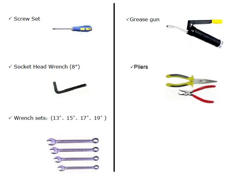
A. Tools requirement
B. Power requirement
The electrical source must be 2.2KW minimum. The source cable size must be 2.5mm² and in good condition of contacting with floor.
STEPS OF INSTALLATION
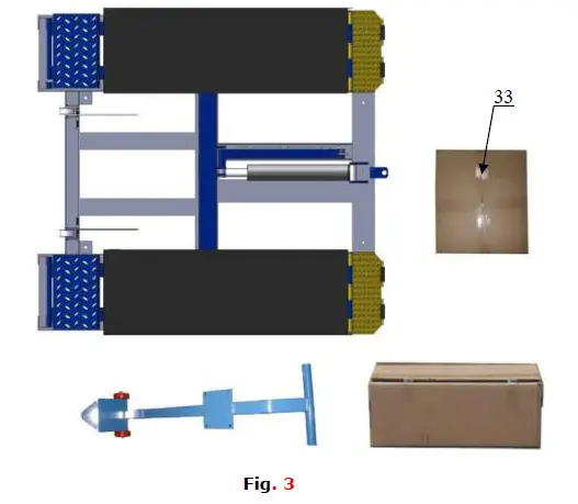
A. Check the parts before assembly, make sure all the parts are completed.
- Packaged lift, Parts box, Power Unit and Power Unit Stand. Move aside the parts, Open the outer packing and check the parts according to the shipment parts list (See Fig. 3).

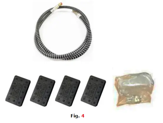
- Open the parts box, check the parts according to the part list (See Fig. 4).

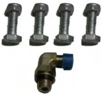
- Check the parts of the parts bag according to the parts bag list (See Fig. 5).

B. Install hydraulic power unit (See Fig. 6)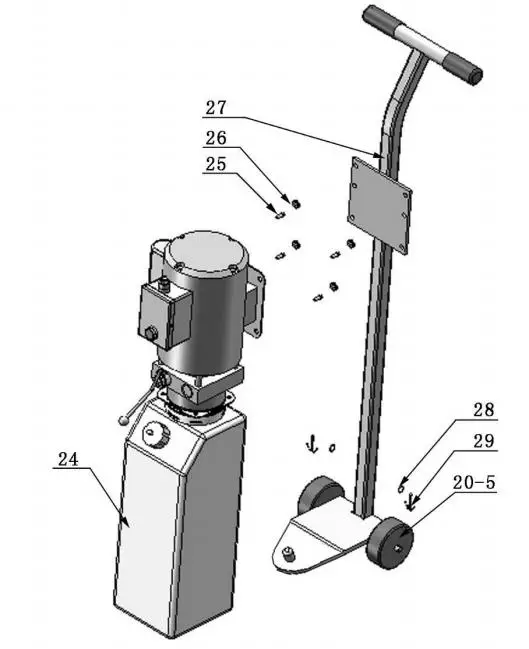
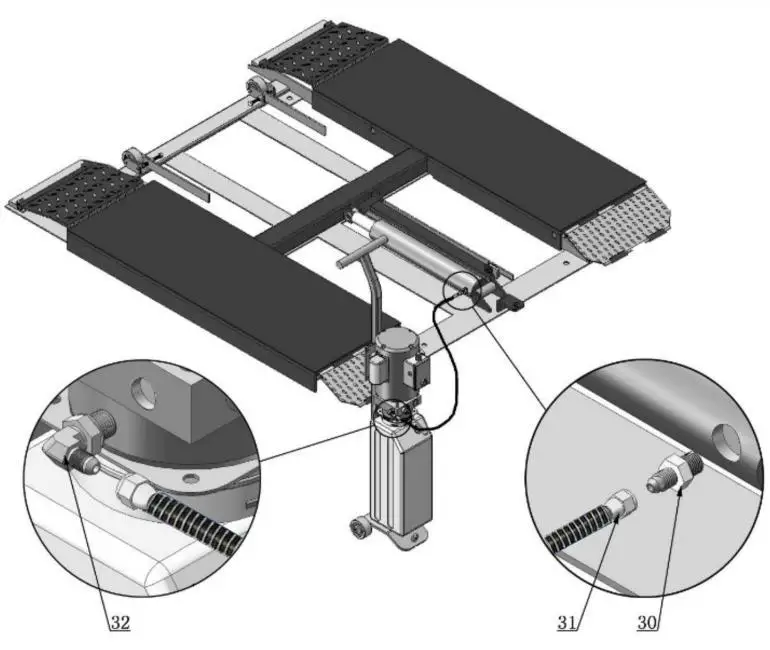
C. Install fitting to power unit, and then connecting oil hose (See Fig.7).
D. Install electrical system
Connect the power source on the data plate of power unit.
Note:
1. For the safety of operators, the power wiring must contact the floor well.
2. Pay attention to the direction of rotations when using three phrases motors.
Single phase motor (Fig.8)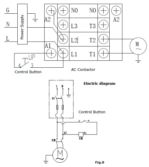 1. Connecting the two power supply lines (fire wire L and zero wire N) to terminals of AC contactor marked L1, L2 respectively.
2. Connecting the two motor wires to terminals of AC contactor marked T1, T2.
3. Connecting L2 to A2 of AC contactor.
4. Connecting two wires of control button to A.C. contactor terminals marked A1、L1.
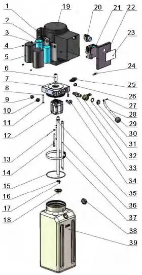
EXPLODED VIEW
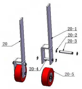
MODEL LR06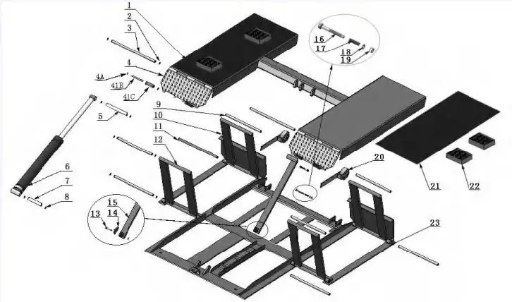 Rollers
PARTS LIST FOR MODEL LR06
| Item | Part# | Description | QTY. | Note |
| 1 | 11630001 | Platform | 1 | |
| 2 | 10206019 | Snap ring | 20 | |
| 3 | 11630003 | Pin for drive-thru ramp | 2 | |
| 4 | 11630004 | Drive-thru ramp | 2 | |
| 4A | 10209010 | Snap Ring | 8 | |
| 4B | 11620043 | Pin for roller of drive-in ramp | 4 | |
| 4C | 10620063 | Roller of drive-pin ramp | 4 | |
| 5 | 11630005 | Connecting pin for cylinder | 1 | |
| 6 | 10630006 | Cylinder | 1 | |
| 7 | 11630007 | Cylinder base connecting pin | 1 | |
| 8 | 10206032 | Snap ring | 4 | |
| 9 | 11630008 | Frame support connecting pin (Upper) | 4 | |
| 10 | 11630009 | Frame support (Front) | 2 | |
| 11 | 11630010 | Frame support connecting pin (Lower) | 4 | |
| 12 | 11630011 | Frame support (Rear) | 2 | |
| 13 | 10630100 | Socket bolt | 1 | |
| 14 | 11630013 | Safety block | 1 | |
| 15 | 11630014 | Safety bar set | 1 | |
| 16 | 10420020 | Hex bolt | 2 | |
| 17 | 10630015 | Spring | 2 | |
| 18 | 10209022 | Washer | 2 | |
| 19 | 10209056 | Self Locking Nut. | 3 | |
| 20 | 10640024 | Rollers | 2 | |
| 21 | 10630102 | Rubber block | 2 | |
| 22 | 10620034 | Rubber pad | 4 | |
| 23 | 11630012 | Base frame | 1 | |
| 24 | 81513008 | Manual power unit | 1 | |
| 25 | 10209003 | Hex bolt | 4 | |
| 26 | 10209005 | Self Locking Nut | 4 | |
| 27 | 10640021 | Power unit stand | 1 | |
| 28 | 10206006 | Washer | 2 | |
| 29 | 10420046 | Split pin | 2 | |
| 30 | 10209064 | Straight Fitting | 1 | |
| 31 | 1003025001 | Oil hose Assy.( with spring) | 1 | |
| 32 | 10209060 | 90° Fitting for power unit | 1 | |
| 33 | 10630500 | Parts Box | 1 | |
| 34 | 100315001 | Protecting spring for oil hose | 1 | |
| PARTS FOR ROLLER | ||||
| 20-1 | 11630031 | Rollers handle | 2 | |
| 20-2 | 10630032 | Snap Ring | 8 | |
| 20-3 | 11630033 | Connecting Shaft | 2 | |
| 20-4 | 11630034 | Roller Shaft | 2 | |
| 20-5 | 10640023 | Roller | 4 | |
Cylinder
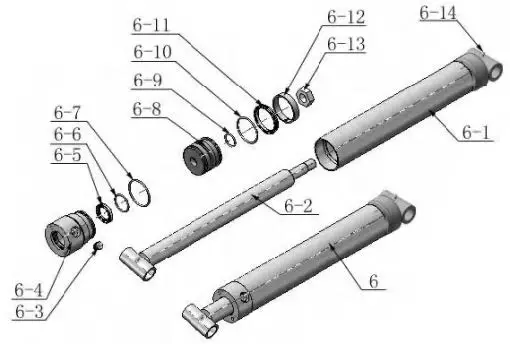
| Item | Part No. | Description | QTY. | Note |
| 6-1 | 11630029 | Bore Weldment | 1 | |
| 6-2 | 11630026 | Piston Rod | 1 | |
| 6-3 | 10201034 | Bleeding Plug | 1 | |
| 6-4 | 11630030 | Head cap | 1 | |
| 6-5 | 10209078 | Dust ring | 1 | |
| 6-6 | 10620058 | O – Ring | 1 | |
| 6-7 | 10620049 | O – Ring | 1 | |
| 6-8 | 11630028 | Piston | 1 | |
| 6-9 | 10206069 | O-Ring | 1 | |
| 6-10 | 10630027 | O-Ring | 1 | |
| 6-11 | 10620054 | Y-Ring | 1 | |
| 6-12 | 10620055 | Support Ring | 1 | |
| 6-13 | 10206071 | Nut | 1 | |
| 6-14 | 10620064 | Greasing Fitting | 2 |
Manual Power Unit (071104)
Manual Power Unit 220V/50/60HZ Single Phase
| Item | Part No. | Description | QTY. | Note |
| 1 | 81400180 | Rubber Pad | 2 | |
| 2 | 81400130 | Starting capacitor | 1 | |
| 3 | 81400088 | Running capacitor | 1 | |
| 4 | 10420148 | Cup head bolts with washer | 4 | |
| 5 | 81400066 | Cover for capacity | 2 | |
| 6 | 81400363 | Motor Connecting Shaft | 1 | |
| 7 | 090106 | Manifold Block | 1 | |
| 8 | 10209149 | Lock Washer | 4 | |
| 9 | 81400276 | Plug | 1 | |
| 10 | 81400259 | Plug | 1 | |
| 11 | 85090142 | Socket Bolt | 4 | |
| 12 | 81400280 | Gear pump | 1 | |
| 13 | 10209034 | Lock Washer | 2 | |
| 14 | 81400295 | Socket Bolt | 2 | |
| 15 | 81400365 | O Ring | 1 | |
| 16 | 10209152 | Belt | 1 | |
| 17 | 85090167 | Magnet | 1 | |
| 18 | 81400290 | Filter | 1 | |
| 19 | 81400413 | Motor | 1 | |
| 20 | 10420070 | Push Button | 1 | |
| 21 | 41030055 | AC Contactor | 1 | |
| 22 | 81400287 | Cover of Motor terminal box | 1 | |
| 23 | 71111174 | AMGO label | 1 | |
| 24 | 81400560 | Throttle valve | 1 | |
| 25 | 81400266 | Relief Valve | 1 | |
| 26 | 81400284 | Plug | 1 | |
| 27 | 10720118 | Elastic latch | 1 | |
| 28 | 81400451 | Release valve handle | 1 | |
| 29 | 10209020 | Black plastic ball | 1 | |
| 30 | 81400421 | Release valve Nut | 1 | |
| 31 | 81400422 | Release valve washer | 1 | |
| 32 | 81400449 | Release valve seat | 1 | |
| 33 | 070001 | Release Valve | 1 | |
| 34 | 070002 | Check valve | 1 | |
| 35 | 81400288 | Oil suction pipe | 1 | |
| 36 | 81400289 | Oil return pipe | 1 | |
| 37 | 81400364 | Clamp | 1 | |
| 38 | 81400263 | Oil tank cap | 1 | |
| 39 | 81400320 | Oil tank | 1 |
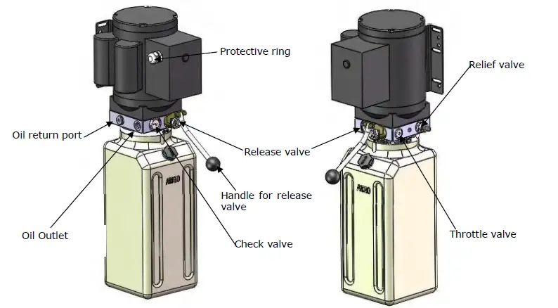
Illustration of hydraulic valve for power unit
OPERATION INSTRUCTIONS
- Install the oil hose between oil cylinder and power unit, connect well the power supply wire. The machine can be ready to use.
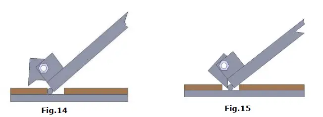
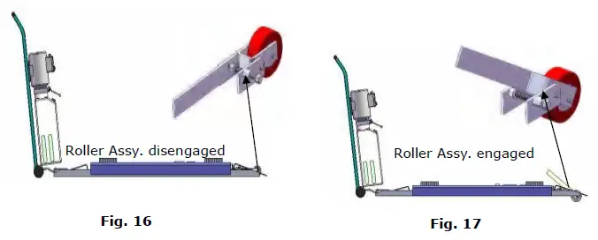
- The roller must be disengage when lifting vehicle (See Fig.16). To raise and lock the lift: Press the button up till the lift is raised to the required height and the locks are in engaged (See Fig.14), then push release handle of the power unit, the lift would be locked.
- To lower lift:Press the button UP, until the safety lock is in the released position (See Fig.15), lower lift by pushing lowering handle.

- Move lift: Pull up roller bracket, lock two roller to the lift with roller shaft. (See Fig. 16& 17 ). Moving the lift by the power unit stand.

- There are four fixed holes in the machine, can fix the machine on ground by 3/4 X 4 3/4” anchor bolts (See Fig.18).

MAINTENANCE SCHEDULE
Monthly:
1. Lubricate all moving parts with lubricant.
2. Check all connectors, bolts and pins to insure proper mounting.
3. Make a visual inspection of all hydraulic hoses/lines for possible wear or leakage.
Every six months:
- Make a visual inspection of all moving parts for possible wear, interference or damage.
- Check all fastener and re-torque.
TROUBLESHOOTING
| TROUBLE | CAUSE | REMEDY |
| 1. Start Button does not work 2. Wiring connections are not in good condition 3. Motor burned out 4. AC contactor burned out | 1. Replace start button 2. Repair all wiring connections | |
| Motor does not run | 3. Repair or replace motor 4. Replace AC Contactor | |
| Motor runs but the lift is not raised | 1. Motor runs in reverse rotation 2. Gear Pump out of operation 3. Release Valve in damage 4. Relief Valve or Check Valve in damage 5. Low oil level 6. Overload or system low pressure | 1. Reverse two power wire 2. Repair or replace 3. Repair or replace 4. Repair or replace 5. Fill tank 6. Check load or adjusting the pressure of hydraulic system |
| Lift does not stay up | 1. Release Valve out of work 2. Relief Valve or Check Valve leakage 3. Cylinder or Fittings leaks | Repair or replace |
| Lift raises slowly | 1. Oil line is jammed 2. Motor running on low voltage 3. Oil mixed with air 4. Gear Pump leaks 5. Overload lifting | 1. Clean the oil line 2. Check electrical system 3. Fill tank 4. Repair or replace pump 5. Check load |
| Lift can not lower | 1. Safety device are in activated 2. Release valve in damage 3. Oil system is jammed | 1. Release the safeties 2. Repair or replace 3. Replace Clean the oil system |
Lift disposal.
When the car lift cannot meet the requirements for normal use and needs to be disposed of, it should follow local laws and regulations.


