PEAK MR06 Portable Mid Rised Lift Instruction Manual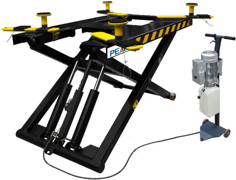
PRODUCT FEATURES AND SPECIFICATIONS
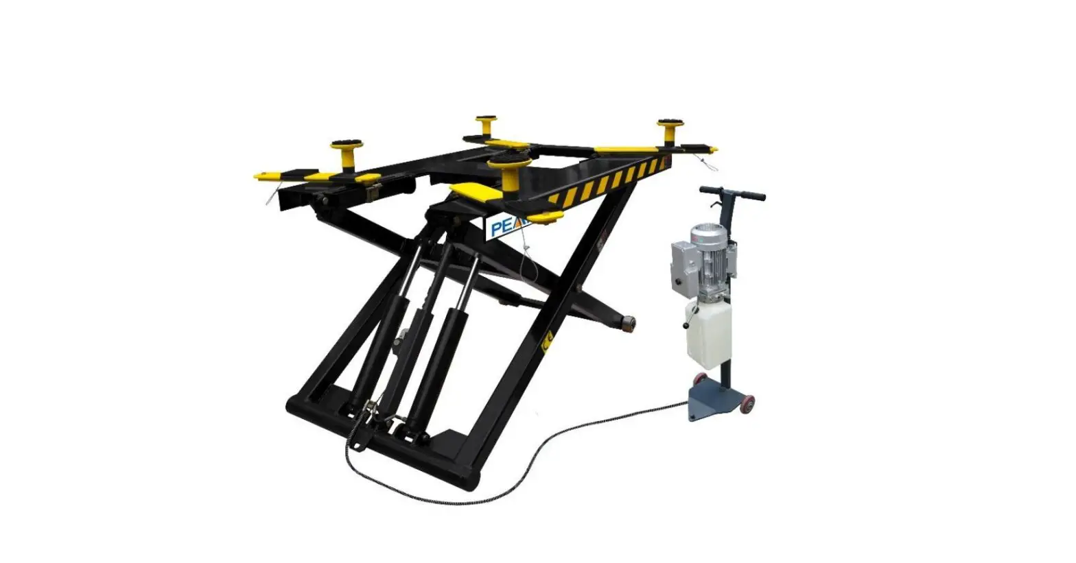
PORTABLE MID-RISED MODEL MR06
- Manual safety lock: mechanical safety locks release, No need air source.
- High speed: From 0-1090mm (43”) in just 21 seconds
- Portable design: It is easy to move the whole lift with the power unit stand
- Adjustable rubber pad included
MODEL MR06 SPECIFICATIONS
| Model | Lifting Capacity | Raised Height | Lifting Time | Overall Length | Platform Width | Lowered Height | Motor |
| MR06 | 2.8T6,000 lbs | 1090mm 43” | 21S | 1885mm 74 1/4 | 1000mm 39 3/8” | 125mm 5” | 1.5HP/3.0HP |
INSTALLATION REQUIREMENT
- Screw Set

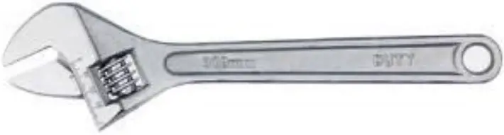
- English Spanner (12″)

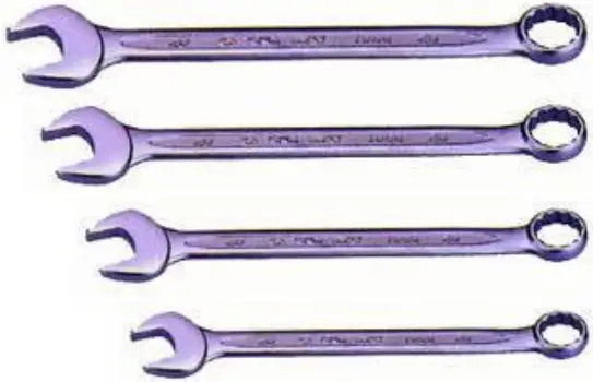
- Wrench sets: (13 #、15 #、17 #、19 # )

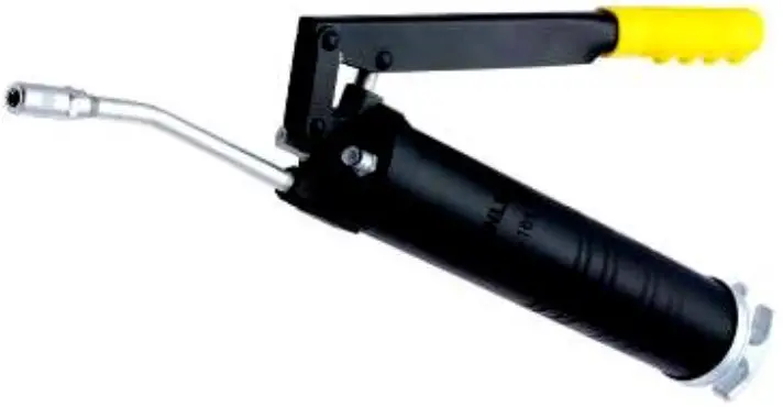
- Grease gun

- Hook spanner (40~42mm)

- Pliers


B. POWER SUPPLY
The electrical source must be 2.2kw minimum. The source cable size must be2.5mm² and in good condition of contacting with floor.
INSTALLATION STEPS
A. Check the parts before assembly, make sure all the parts arecompleted.
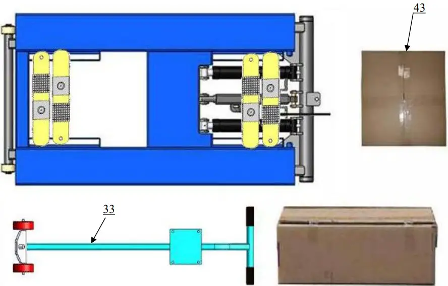
- Packaged lift, Parts box, Power Unit and Power Unit Stand. Move the parts aside, open the outer packing and check the parts according to the shipment parts list (See Fig. 3).

- Open the parts box, check the parts according to the part list (See Fig. 4).

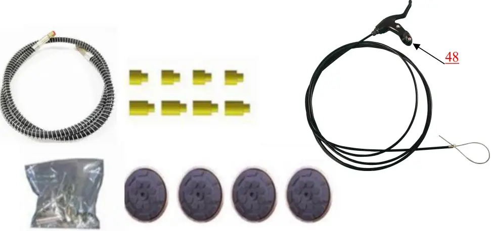
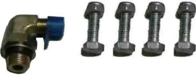
- Check the parts of the parts bag according to the parts bag list (See Fig. 5).

B. Install the brake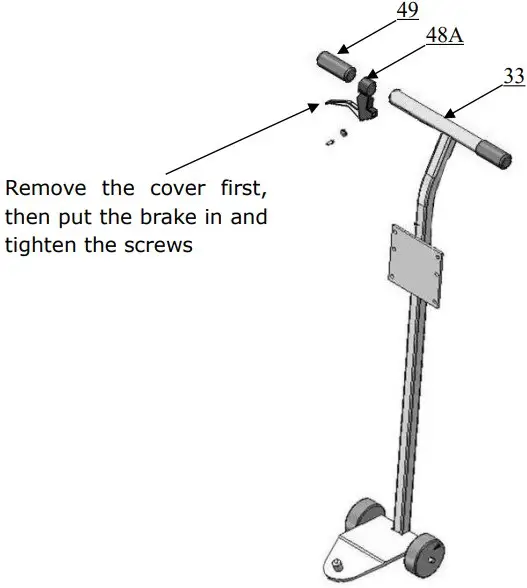
Then Install hydraulic power unit and fitting (See Fig. 7)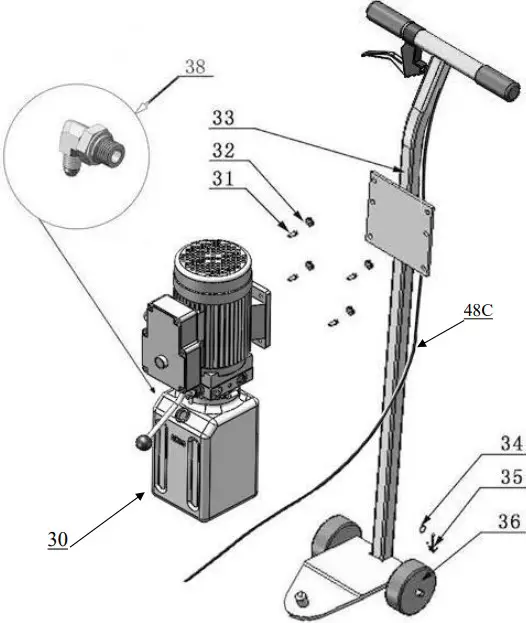
C. Install oil hose (See Fig. 8)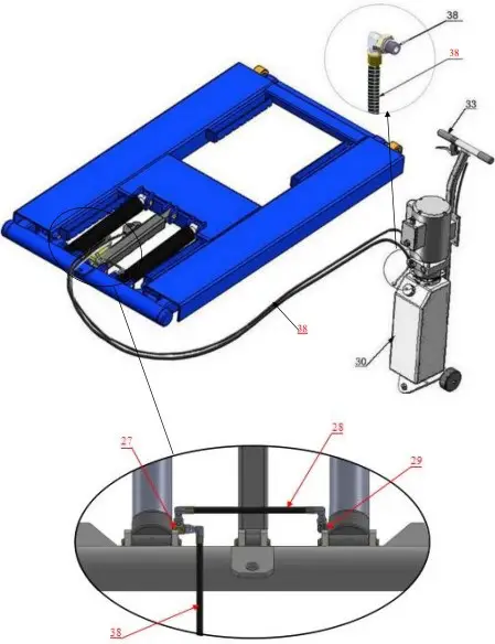
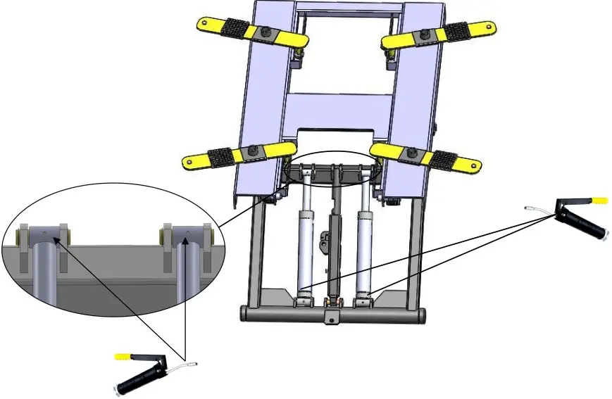
D. Install safety device and cable
- Put the safety device parts as Fig.9

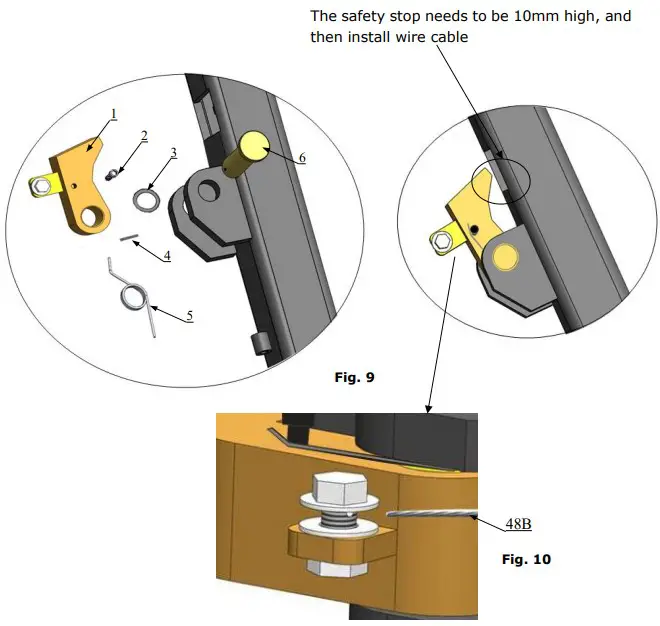
Put the small wire rope into the hole on the screwandthentighten
| Item | Part# | Description | QTY |
| 1 | 11640150 | Safety stop | 1 |
| 2 | 81400438 | Hex bolt M5*10 | 1 |
| 3 | 10510053 | Washer | 1 |
| 4 | 1061K104 | Split pinφ3*30 | 1 |
| 5 | 10640155 | Springφ23*φ27*2 | 1 |
| 6 | 11640154 | Safety pin | 1 |
E. Tighten supporting arm
- Raise the lift up to 1000mm and lock the safety device, then tighten the self-locknut
Make sure the supporting arms not move left/right (See Fig. 11)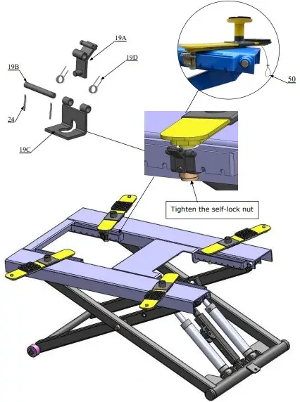
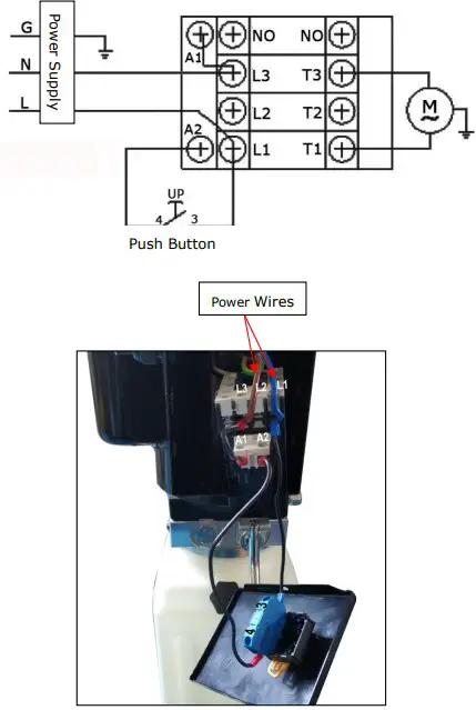
F Install electric system
Connect the power source on the data plate of Motor
Note:
- For the safety of operators, the power wiring must contact the floor well.
- Pay attention to the direction of rotations when using three phase motors.
Single phase motor (See Fig. 12)
- Connecting the two power supply wires (fire wire L and zero wire N) toterminalsofAC contactor marked L1, L3. The ground wire is connected to the groundwireterminal.

EXPLODED VIEW
Model MR06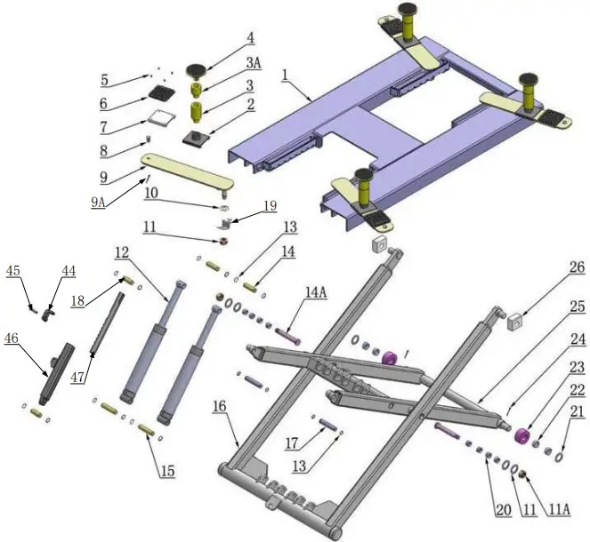
PARTS LIST FOR MODEL MR06
| Item | Part# | Description | QTY. | Note | |
| 1 | 11640001 | Platform | 1 | ||
| 2 | 11640002A | Stackable Adapter Bracket | 4 | ||
| 3 | 11209052B | Stackable Adapter (2.5”) | 4 | ||
| 4 | 11209051B | Stackable Adapter (1.5”) | 4 | ||
| 5 | 10209009 | Cup Head Bolt | 16 | ||
| 6 | 10680004 | Rubber Pad | 4 | ||
| 7 | 10640003 | Supporting pad | 4 | ||
| 8 | 11640023A | Limit pin | 4 | ||
| 9 | 11640004 | Supporting arm | 4 | ||
| 10 | 10640005 | Washer | 10 | ||
| 11 | 10640109 | Washer | 4 | ||
| 11A | 10620022 | Self-locking Nut | 6 | ||
| 12 | 10640116 | Cylinder | 2 | ||
| 13 | 10206032 | Snap Ring | 12 | ||
| 14 | 11640057 | Pin for Cylinder Connecting | 2 | ||
| 14A | 11640012 | Pin | 2 | ||
| 15 | 11640006A | Pin for Cylinder | 2 | ||
| 16 | 11640017B | Outer Scissor | 1 | ||
| 17 | 11640009 | Inner Scissor Pin | 2 | ||
| 18 | 11640130 | Safety Bar Set | 2 | ||
| 19 | 19A | 11640134 | Slide limit block | 4 | |
| 19B | 11640135 | Slide stop | 4 | ||
| 19C | 11640136 | Safety Pin | 4 | ||
| 19D | 10640127 | Spring | 8 | ||
| 20 | 10203004A | Bronze Bush | 8 | ||
| 21 | 10420023A | Washer | 2 | ||
| 22 | 10420132A | Bronze Bush | 4 | ||
| 23 | 11640022 | Roller | 2 | ||
| 24 | 10630107 | Split Pin | 10 | ||
| 25 | 11640016B | Inner Scissor | 1 | ||
| 26 | 10610003A | Slider | 2 | ||
| 27 | 10209060 | Fitting 1/4JIC(M)*1/4JIC(M)*1/4NPT(M) | 1 | ||
| 28 | 10640114-01 | Oil Hose 1/4²*215 | 1 | ||
| 29 | 10420097 | 900 Fitting 1/4JIC(M)*1/4NPT(M) | 1 | ||
| 30 | 81513006 | Power Unit 220V | 1 | ||
| 81513019 | Power Unit 110V | 1 | |||
| 31 | 10209003 | Hex Bolt | 4 | ||
| 32 | 10209005 | Self Locking Nut | 4 | ||
| 33 | 10640138 | Power Unit Stand | 1 | ||
| 34 | 10206006 | Washer F12 | 2 | ||
| 35 | 10201005 | Split Pin | 2 | ||
| 36 | 1003275021 | White Roller | 2 | ||
| 37 | 10209060 | Powr Unit 900 Fitting | 1 | ||
| 38 | 1003015002 | Oil Hose Assy (include spring) | 1 | ||
| 39 | 10201046A | Rubber Pad Assy. | 4 | ||
| 40 | 10420138 | M6*16 Socket Bolt | 4 | ||
| 41 | 10209134 | Rubber Pad | 4 | ||
| 42 | 11680030C | Support Frame | 4 | ||
| 43 | 10640500A | Part Box | 1 | ||
| 44 | 11640150 | Safety Guard | 1 | ||
| 45 | 11640154 | Safety Guard Pin φ22*74 | 1 | ||
| 46 | 11640153 | Self Locking Support Tube | 1 | ||
| 47 | 11640699 | Self Locking Support Shaftφ45*493 | 1 | ||
| 48 | 10640141 | Brake Handle Assy (with cable) | 1 | ||
| 48A | 10640115 | Brake handle | 1 | ||
| 48B | 10640156 | Safety Cable φ1.5*4345mm | 1 | ||
| 48C | 10640121 | Brake wire pipe φ5*φ2*4060mm | 1 | ||
| 49 | 10640126 | Brake handle rubber cover | 1 | ||
| 50 | 10640133 | Safety Cable φ2.5*810mm | 4 | ||
CYLINDER (10640116)
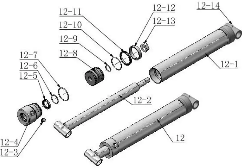
PARTS FOR HYDRAULIC CYLINDER
| Item | Part# | Description | QTY. | Note |
| 12-1 | 11640657 | Bore Weldment | 2 | |
| 12-2 | 11640031A | Piston Rod | 2 | |
| 12-3 | 10201034 | Bleeding Plug | 2 | |
| 12-4 | 11203083 | Head Cap | 2 | |
| 12-5 | 10209078 | Dust Ring | 2 | |
| 12-6 | 10201032 | O – Ring | 2 | |
| 12-7 | 10203084 | O – Ring | 2 | |
| 12-8 | 11203079 | Piston | 2 | |
| 12-9 | 10206069 | O-Ring | 2 | |
| 12-10 | 10203082 | O-Ring | 2 | |
| 12-11 | 10410087 | Y-Ring | 2 | |
| 12-12 | 10410086 | Support Ring | 2 | |
| 12-13 | 10206071 | Nut | 2 | |
| 12-14 | 10620064 | Greasing Fitting | 4 |
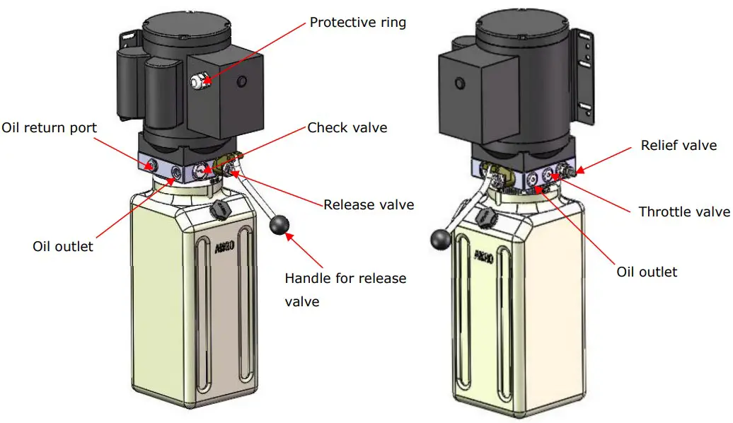
MANUAL POWER UNIT (81513006)
220V/50HZ/1 phase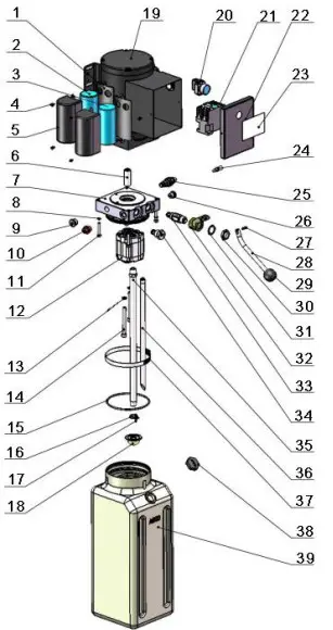
Parts for Manual power unit
| Item | Part# | Description | QTY. | Note |
| 1 | 81400180 | Rubber pad | 2 | |
| 2 | 81400250 | Start capacitor | 1 | |
| 3 | 81400200 | Run capacitor | 1 | |
| 4 | 10420148 | Cup head bolt with washer | 4 | |
| 5 | 81400066 | Cover for capacitor | 2 | |
| 6 | 81400363 | Motor connecting shaft | 1 | |
| 7 | 80101013 | Manifold block | 1 | |
| 8 | 10209149 | Lock washer | 4 | |
| 9 | 81400276 | Iron plug | 1 | |
| 10 | 81400259 | Red rubber plug | 1 | |
| 11 | 85090142 | Socket bolt | 4 | |
| 12 | 81400280 | Gear pump | 1 | |
| 13 | 10209034 | Washer | 2 | |
| 14 | 81400295 | Socket bolt | 2 | |
| 15 | 81400365 | O-ring | 1 | |
| 16 | 10209152 | Belt | 1 | |
| 17 | 85090167 | Magnet | 1 | |
| 18 | 81400290 | Filter mesh | 1 | |
| 19 | 81400413 | Motor | 1 | |
| 20 | 10420070 | Button switch | 1 | |
| 21 | 41030055 | AC contactor | 1 | |
| 22 | 81400287 | Cover of motor terminal box | 1 | |
| 23 | 71111216 | AMGO label | 1 | |
| 24 | 81400560 | Throttle valve | 1 | |
| 25 | 81400266 | Release valve | 1 | |
| 26 | 81400284 | Iron plug | 1 | |
| 27 | 10720118 | Hair pin | 1 | |
| 28 | 81400451 | Handle for release valve | 1 | |
| 29 | 10209020 | Plastic ball for arm lock | 1 | |
| 30 | 81400421 | Release valve nut | 1 | |
| 31 | 81400422 | Release valve shim | 1 | |
| 32 | 81400449 | Valve seat(Low) | 1 | |
| 33 | 81400567 | Release valve | 1 | |
| 34 | 81400566 | Check valve | 1 | |
| 35 | 81400375 | Oil suction pipe | 1 | |
| 36 | 81400376 | Oil return pipe | 1 | |
| 37 | 81400364 | Hose clamp (stainless steel) | 1 | |
| 38 | 81400263 | Oil tank cap | 1 | |
| 39 | 81400320 | Oil tank | 1 |
Manual Power unit 220V 50Hz single phase (See.Fig16)
OPERATION INSTRUCTIONS
- Install the oil hose between oil cylinder and power unit, connect withthepowersupply wire well. The machine can be ready to use.
- When lifting vehicle, be sure the center of gravity of vehicle must be inthemiddleof lift, select the suitable adapters , pull the small cable of the yellowsupport armsto open the lock ,and move the arms to find the support point. (SeeFig.18,19)Make sure the safety lock must be in engaged when lifting (See Fig. 20).
- Lower the lift: Press the button “UP”, until the safety lock is in releasedpositionclench the brake handle(See Fig.21,22), lower the lift by pushing loweringhandle
Pull cable to move supporting arm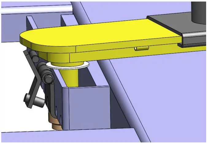
Relax cable to fasten supportingarm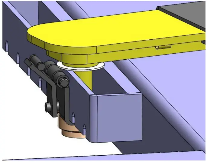
Safety engaged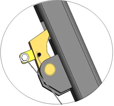
Safety released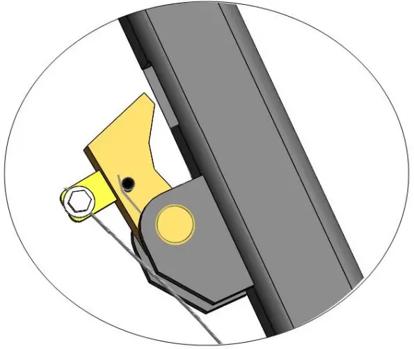
Clench the brake handle to release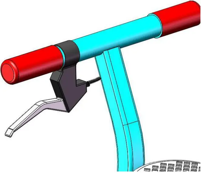
Move the lift with the power unit stand (See Fig. 22)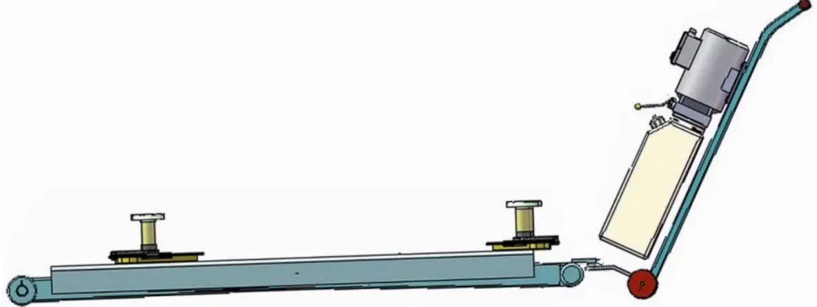
MAINTENANCE SCHEDULE
Monthly:
- Lubricate all moving parts with lubricant (See Fig.23).

- Check all connectors, bolts and pins to insure proper mounting.
- Make a visual inspection of all hydraulic hoses/lines for possible wear or leakage.
Every six months:
- Make a visual inspection of all moving parts for possible wear, interferenceordamage.
- Check all fastener and re-torque.
Cylinder Maintenance and Maintenance:
In order to extend the life of the cylinder, please follow the following requirements.
- Recommended N46 anti-wear hydraulic oil;
- Replace the oil regularlly. Replace the first time 3 months after installation,thereplace yearly.
- Take at least a full stroke run everyday to bleed out the possible exit air. Thisoperation would effectively avoid the air or water that cause cylinder corrosionandsealkit damage.
- Protect the outer surface of the cylinder piston rod to prevent bumps andscratches,clean up the position of the cylinder dustpower and the debris on the pistonrodintime.
TROUBLE SHOOTING
| TROUBLE | CAUSE | REMEDY |
| Motor does not run |
|
|
| Motor runs but the lift is not raised |
|
|
| Lift does not stay up |
| Repair or replace |
| Lift raises slowly |
|
|
| Lift cannot lower |
|
|
Lift disposal
When the car lift cannot meet the requirements for normal use andneedstobedisposed, it should follow local laws and regulations.
PEAK CORPORATION
No. 3 Luomu Road, Shishan Town, Nanhai Distric t,Foshan(528225),Guangdong,ChinaTel:86-757-81102815 8112805 Fax: 86-757-81102809
Email: [email protected]
http://www.peaklift.cn
Manual Part No.: 72206408
Revision Date: 2022/03