![]() Original
Original
Installation And Service Manual
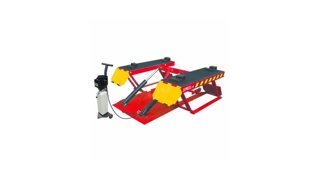
Portable Low-rise scissors lift Model: LRlO
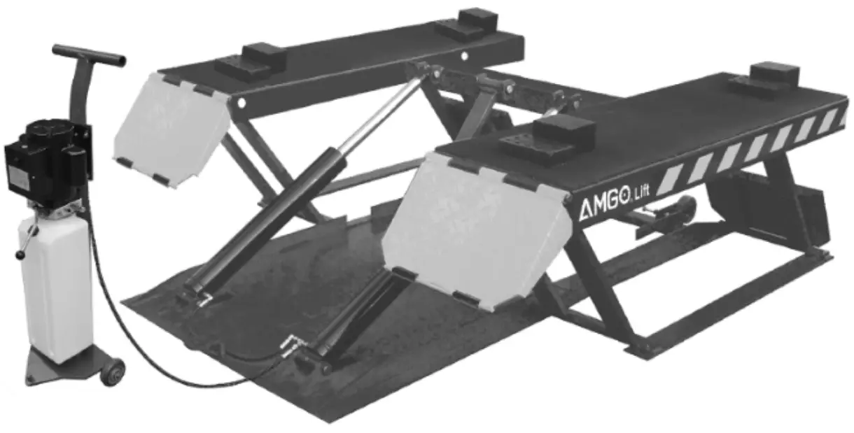
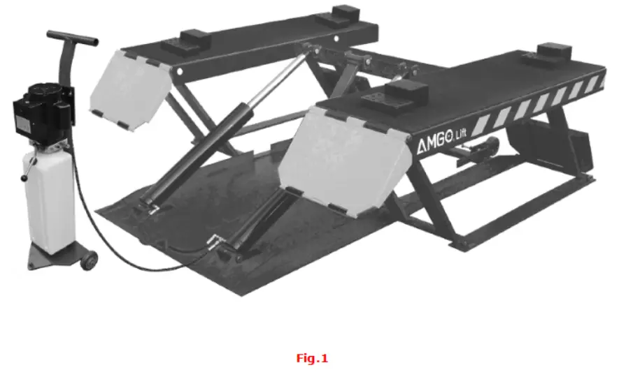
PRODUCT FEATURES AND SPECIFICATIONS (See Fig.1)
PORT ABLE LOW-RISED MODEL LRlO
- Self-locking safety device: 3 stage safety lock, mechanical lock, automatic release.
- Portable unit is easy to move with the power unit stand
- Double cylinder design.
- Multifunctional drive-in ramp can also be used as an extension platform.
- High speed: From 0-23 5/8″ in just 42 seconds
- Standard rubber pads induced
MODEL LRlO SPECIFICATIONS
| Model | Lifting Capacity | Raised Height | Lifting Time | Overall Length | Overall Width | Lowered Height | Runway Width | Runway Length | Gross Weight | Motor |
| LR10 | 10000 LBS | 23 5/8″ | 505 | 76 1/4″ | 70″ | 4 1/8″ | 18″ | 53 1/4″ | 1,06316: | 2.0 HP |
INSTALLATION REQUIREMENT
A. Tools requirement
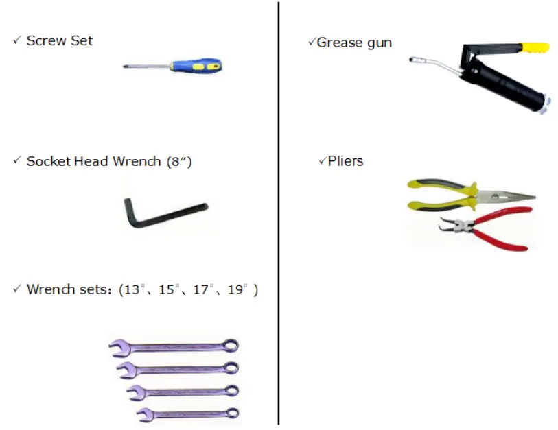
Fig.2
B. Power requirement
The electrical source must be 2.2KW minimum. The source cable size must be 2.5mm? and in good condition of contact with a floor.
STEPS OF INSTALLATION
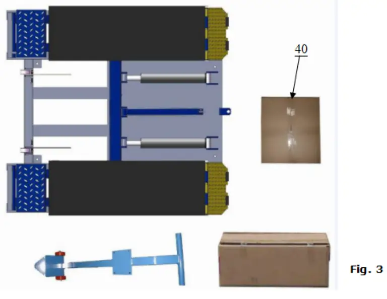
A. Check the parts before assembly, make sure all the parts are completed.
- Packaged lift, Parts box, Power Unit, and Power Unit Stand Move aside the parts, Open the outer packing and check the parts according to the shipment parts list (See Fig. 3)

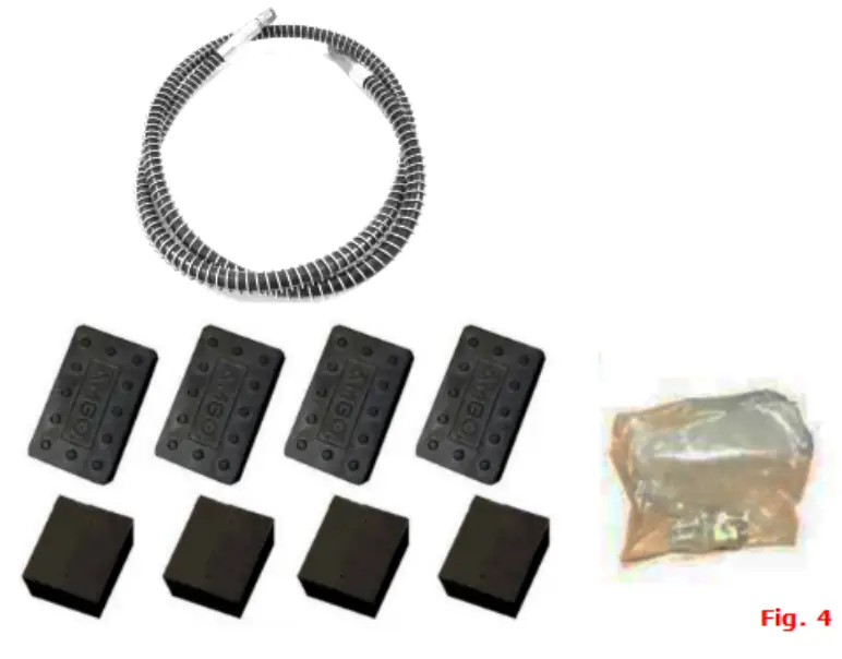
- Open the parts box, check the parts according to the part list (see Fig. ).

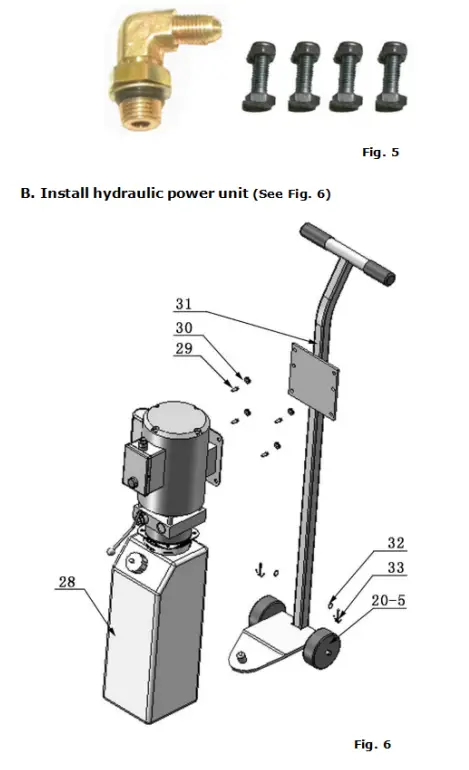
- Check the parts of the parts bag according to the parts bag list (See Fig. 5).

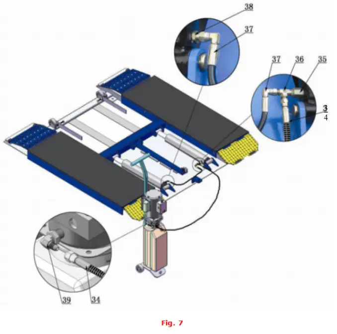
C. Install fitting to the power unit, and then connect oil hose (see Fig.7). D. Install electrical system
Connect the power source on the data plate of the power unit.
Note: 1. For the safety of operators, the power wiring must contact the floor well. 2. Pay attention to the direction of rotations when using three phrases motors.
 D. Install electrical system
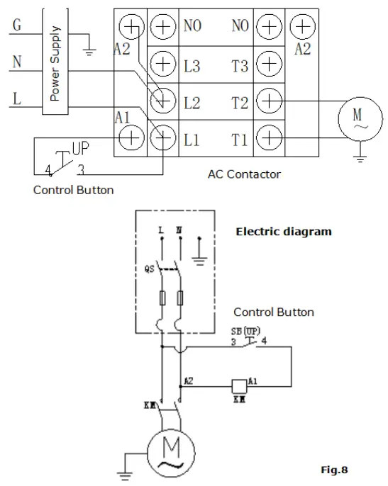
Single phase motor (Fig.8)
- Connecting the two power supply lines (firewire L and zero wire N) to terminals of AC contactor markedL1, L2 respectively.
- Connecting the two motor wires to terminals of AC contactor marked T1, T2
- Connecting L2 to A2 of AC contactor.
- Connecting two wires of the control button to A.C. contactor terminals marked A1 Ll.
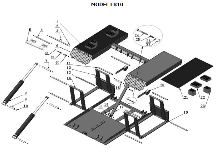
EXPLODED VIEW
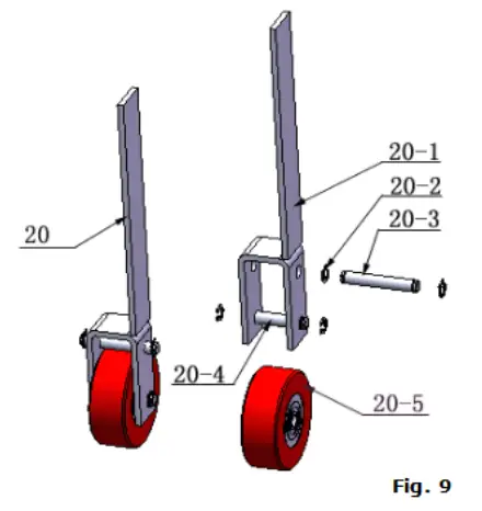
Rollers
PARTS LIST FOR MODEL LR10
| Item | Part* | Description | QTY. | Note |
| 1 | 11630001A | Platform | 1 | |
| 2 | 10206019 | Snap Ringφ19 | 24 | |
| 3 | 11630003 | Pin for drive-in ramp φ19”452 | 2 | |
| 4 | 11630106 | Bracket Pin φ19”410 | 2 | |
| 5 | 11620006A | Bracket | 2 | |
| 6 | 11630108 | Drive-in ramp | 2 | |
| 6A | 10209010 | Snap Ring φ10 | 8 | |
| 6B | 11620043 | Roller Pin for drive-in ramp | 4 | |
| 6C | 10620063 | Roller for drive-in ramp (black nylon) | 4 | |
| 7 | 11630109 | Cylinder Connecting pinφ25*92 | 2 | |
| 8 | 10630006 | Cylinder | 2 | |
| 9 | 11630007 | Cylinder case connecting pin φ25”132 | 2 | |
| 10 | 10206032 | Snap Ring φ25 | 10 | |
| 11 | 11630008 | Frame Support connect pin upper | 4 | |
| 12 | 11630009 | Frame support (front) | 2 | |
| 13 | 11630010 | Frame Support connect pin φ19”405 | 4 | |
| 14 | 11630011 | Frame Support | 2 | |
| 15 | 10630100 | Socket Bolt M10*40 | 1 | |
| 16 | 11630013 | Safety Block | 1 | |
| 17 | 11630014 | Safety Support | 1 | |
| 18 | 11630105 | Pin for Safety Support φ25”142 | 1 | |
| 19 | 11630111 | Base | 1 | |
| 20 | 11640024 | Roller | 2 | |
| 21 | 10630102 | Rubber Pad 438*1350*5 | 2 | |
| 22 | 10620034 | Rubber Pad 100*120*38 | 4 | |
| 23 | 10610070 | Rubber Pad 100*120*70 | 4 | |
| 24 | 10420020B | Hex Bolt M10*115 | 2 | |
| 25 | 10630015 | Spring φ15*912″55 | 2 | |
| 26 | 10209022 | Washer φ10 | 2 | |
| 27 | 10209056 | Self Locking Nut φ10 | 3 | |
| 28 | 071101 | Power Unit | 1 | |
| 29 | 10209003 | Hex Bolt φ8*25 | 4 | |
| 30 | 10209005 | Self Locking Nut φ8 | 4 | |
| 31 | 11640021 | Power Unit Stand | 1 | |
| 32 | 10206006 | Washer φ12 | 2 | |
| 33 | 10420046 | Split Pin φ3”20 | 2 | |
| 34 | 1003035003 | Oil Hose Assy.(with spring) | 1 | |
| 35 | 10630103 | Straight Fitting | 1 | |
| 36 | 10209062 | T fitting | 1 | |
| 37 | 10630104 | Oil Hose 1/4*550(double 90° ) | 1 | |
| 38 | 10209064 | Straight fitting for cylinder | 1 | |
| 39 | 10209060 | 90 degree fitting for power unit | 1 | |
| 40 | 10630501A | Parts Box | 1 | |
| Item | Part# | Description | QTY. | Note |
| Parts for Roller | ||||
| 20-1 | 11630031 | Rollers handle | 2 | |
| 20-2 | 10630032 | Snap Ring φ12 | 8 | |
| 20-3 | 11630033 | Connecting Shaft φ12″80 | 2 | |
| 20-4 | 11630034 | Roller Shaftφ12:<65 | 2 | |
| 20-5 | 1003275021 | White wheel | 4 | |
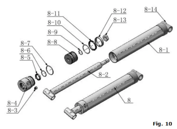
Cylinder
| Item | Part No. | Description | QTY. | Note |
| 8-1 | 11630029 | Bore Weldment | 2 | |
| 8-2 | 11630026 | Piston Rod | 2 | |
| 8-3 | 10201034 | Bleeding Plug | 2 | |
| 8-4 | 11630030 | Head cap | 2 | |
| 8-5 | 10209078 | Dust ring | 2 | |
| 8-6 | 10201035 | 0-Ring inside head cap | , L | |
| 8-7 | 10620049 | 0-Ring outside head cap | 2 | |
| 8-8 | 11630028 | Piston | 2 | |
| 8-9 | 10620050 | Small 0-Ring for piston | 2 | |
| 8-10 | 10630027 | 0-Ring outside piston | 2 | |
| 8-11 | 10620054 | Y-Ring 051 | 2 | |
| 8-12 | 10620055 | Support Ring | 2 | |
| 8-13 | 10206071 | Nut | 2 | |
| 8-14 | 10620064 | Greasing Fitting | 4 |
Manual Power Unit (071101)
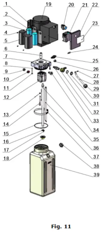
Manual Power Unit 220V/50/60HZ Single Phase
| Item | Part No. | Description | QTY. | Note |
| 1 | 81400180 | Rubber Pad | 2 | |
| 2 | 81400250 | Starting capacitor | 1 | |
| 3 | 81400200 | Running capacitor | 1 | |
| 4 | 10420148 | Cap head bolts with washer | 4 | |
| 5 | 81400066 | Cover for capacity | 2 | |
| 6 | 81400363 | Motor Connecting Shaft | 1 | |
| 7 | 290106 | Manifold Block | 1 | |
| 8 | 10209149 | Lock Washer | 4 | |
| g | 81400276 | Plug(socket iron) | 1 | |
| 10 | 81400259 | Plug(red rubber) | 1 | |
| 11 | 85090142 | Socket Bolt | 4 | |
| 12 | 81400280 | Gear pump | 1 | |
| 13 | 10209034 | Lock Washer | 2 | |
| 14 | 81400295 | Socket Bolt | 2 | |
| 15 | 81400365 | 0 Ring | 1 | |
| 16 | 10209152 | Belt | 1 | |
| 17 | 85090167 | Magnet | 1 | |
| 18 | 81400290 | Filter | 1 | |
| 19 | 81400413 | Motor | 1 | |
| 20 | 10420070 | Push Button | 1 | |
| 21 | 41030055 | AC Contactor | 1 | |
| 22 | 81400287 | Cover of Motor terminal box | 1 | |
| 23 | 71111216 | AMGO label | 1 | |
| 24 | 81400560 | Throttle valve | 1 | |
| 25 | 81400266 | Relief Valve | 1 | |
| 26 | 81400284 | Plug | 1 | |
| 27 | 10720118 | Elastic latch | 1 | |
| 28 | 81400451 | Release valve handle | 1 | |
| 29 | 10209020 | Black plastic ball | 1 | |
| 30 | 81400421 | Release valve Nut | 1 | |
| 31 | 81400422 | Release valve washer | 1 | |
| 32 | 81400449 | Release valve seat (low) | 1 | |
| 33 | 070001 | Release Valve | 1 | |
| 34 | 070002 | Check valve | 1 | |
| 35 | 81400288 | Oil suction pipe | 1 | |
| 36 | 81400289 | Oil return pipe | 1 | |
| 37 | 81400364 | Clamp(stainless steel) | 1 | |
| 38 | 81400263 | Oil tank cap | 1 | |
| 39 | 81400275 | Oil tank | 1 |
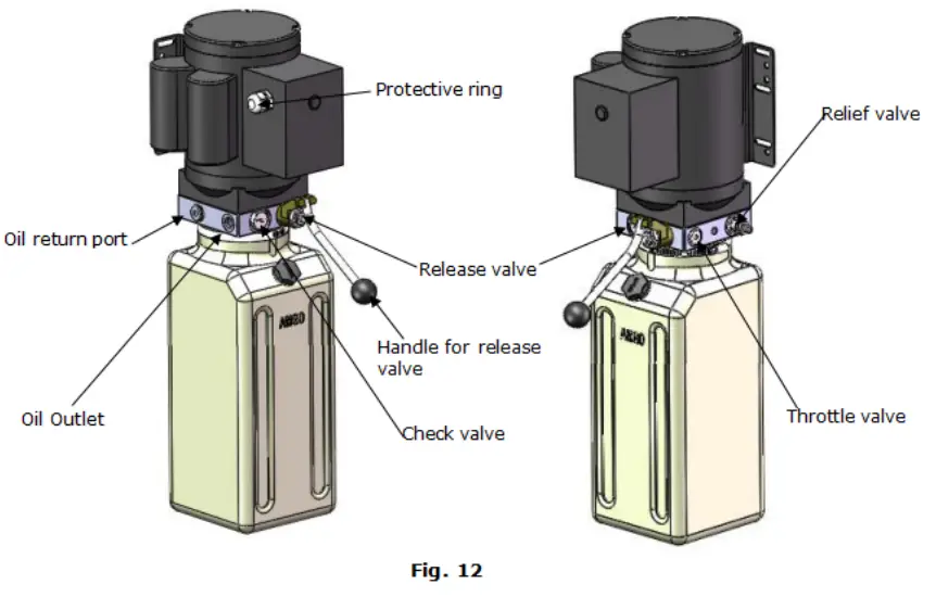
Illustration of hydraulic valve for power unit
OPERATION INSTRUCTIONS
- Install the oil hose between the oil cylinder and power unit, connect well the power supply wire. The machine can be ready to use.
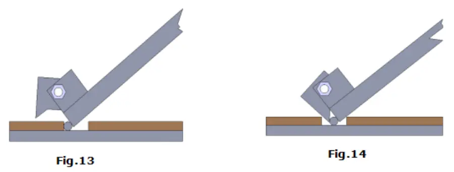
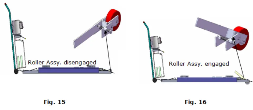
- The roller must be disengaged when lifting the vehicle (See Fig.15). To raise and lock the lift: Press the button up till the lift is raised to the required height and the locks are
in engaged (see Fig.13), then push release handle of the power unit, the lift would be locked - To lower lift: Press the button UP, until the safety lock is in the released position (See Fig.14), lower lift by pushing lowering handle.

- Move lift: Pull up roller bracket, lock two rollers to the lift with roller shaft. (See Fig. 158 16 ), Moving the lift by the power unit stand.

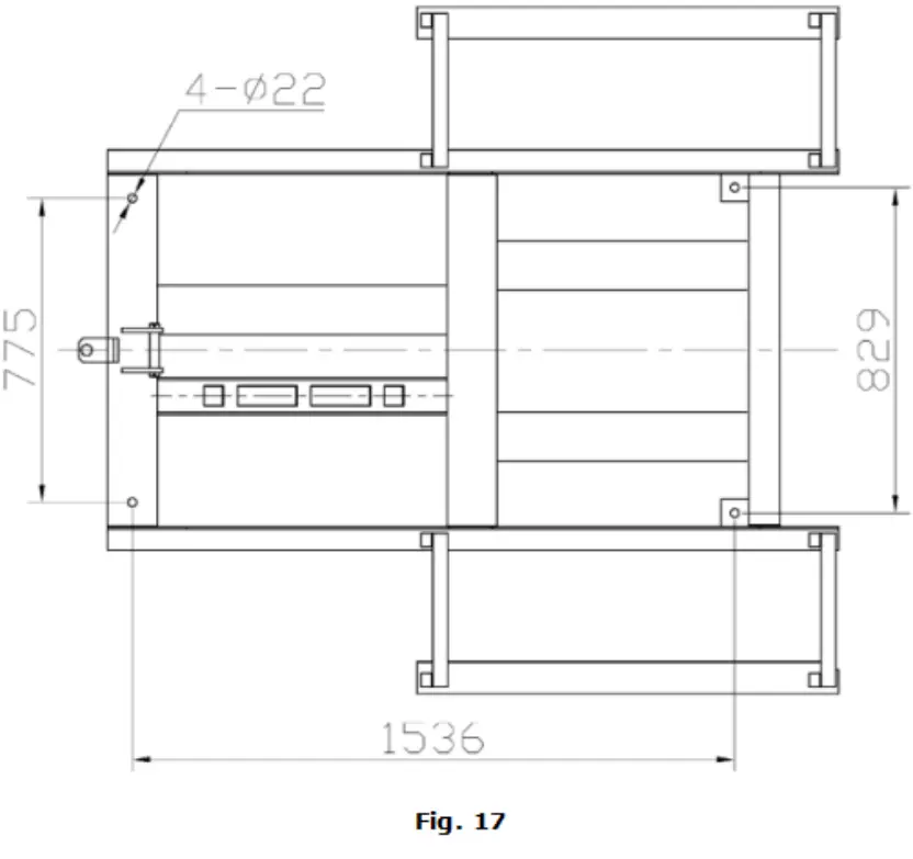
- There are four fixed holes in the machine, can fix the machine on ground by 3/4 X43/4 anchor bolts (see Fig.17)
MAINTENANCE SCHEDULE
Monthly:
- Lubricate all moving parts with lubricant.
- Check all connectors, bolts, and pins to insure proper mounting
- Make a visual inspection of all hydraulic hoses/lines for possible wear or leakage.
Every six months:
- 1. Make a visual inspection of all moving parts for possible wear, interference, or damage.
- Check all fasteners and re-torque.
Oil cylinder maintenance:
In order to extend the service life of the oil cylinder, please operate according to the following requirements.
- Recommend using N46 anti-wear hydraulic oil.
- The hydraulic oil of the lifts should be replaced regularly during use. Replace the hydraulic oil 3 months after the first installation, Replace the hydraulic oil once a year afterward.
- Make at least one full trip raising and lowering per day. For exhausting the air from the system, could effectively avoid the corrosion of the cylinder and damage to the seals caused by the presence of air or water in the system.
- Protect the outer surface of the oil cylinder’s piston rod from bumping and scratching, and timely clean up the debris on the oil cylinder dust-ring and the piston rod.
TROUBLESHOOTING
| TROUBLE | CAUSE | REMEDY |
| Motor does not run | 1. Start Button does not work 2. Wiring connections are not in good condition 3. Motor burned out 4. AC contactor burned out | 1. Replace the Start button 2. Repair all wiring connections 3. Repair or replace the motor 4. Replace AC Contactor |
| Motor runs but the lift is not raised | 1. Motor runs in reverse rotation 2. Gear Pump out of operation 3. Release Valve in damage 4. Relief Valve or Check Valve in damage 5. Low oil level 6. Overload or system low pressure | 1. Reverse two power wire 2. Repair or replace 3. Repair or replace 4. Repair or replace 5. Fill tank 6. Check a load or adjust the pressure of the hydraulic system |
| Lift does not stay up | 1. Release Valve out of work 2. Relief Valve or Check Valve leakage 3. Cylinder or Fittings leaks | Repair or replace |
| Lift raises slowly | 1. Oil line is jammed 2. Motor running on low voltage 3. Oil mixed with air 4. Gear Pump leaks 5. Overload lifting | 1. Clean the oil line 2. Check the electrical system 3. Fill tank 4. Repair or replace the pump 5. Check the load |
| Lift can not lower | 1. Safety device is inactivated 2. Release valve in damage 3. Oil system is jammed | 1. Release the safeties 2. Repair or replace 3. Replace Clean the oil system |
Lift disposal.
When the car lift cannot meet the requirements for normal use and needs to be disposed of, it should follow local laws and regulations.
![]()
AMGO HYDRAULIC CORPORA 110N
1931 Joe Rogers Bvd, Manning, South Carolina
Zip: 29102
Tel. (803) 505-6410
Fax (803) 505-6410
Manual Part No. ; 72215801
Revision Date; 2021/10


