BOHYUN BY-1200A Mobile Scissor Lifter User Manual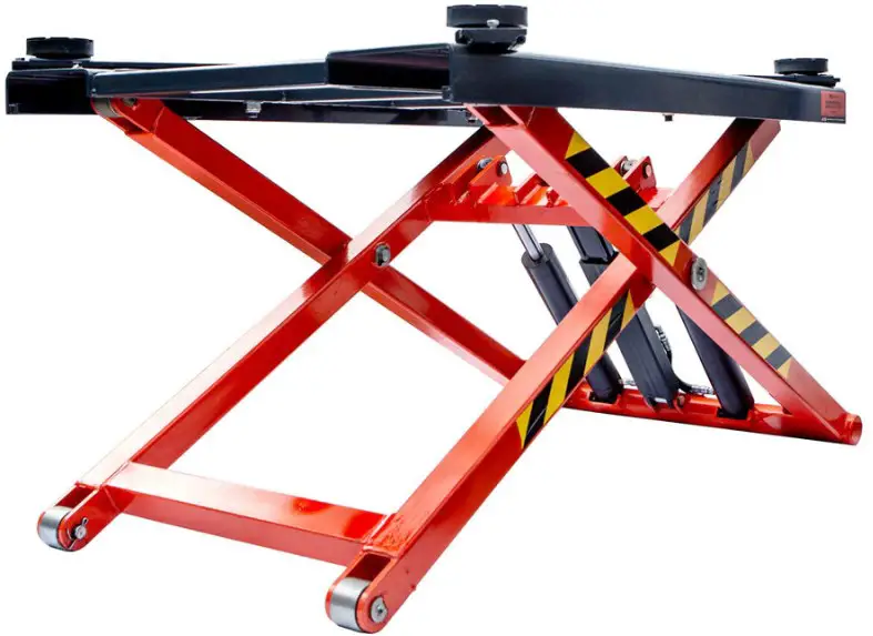
INTRODUCTION
Congratulations on your purchase of this Hydraulic Scissor Lift. This model istheresult of our vast experience in the production of fine lifting vehicles machines. Itrepresents the high degree of craftsmanship and reliability that have madeusaleader in these fields.
It is a wheels free hydraulic lift bridge with a lower profile, designed andbuilt tomeet the requirement of the operator changing tires in the tire shop andfor minormechanical jobs (oil change, changing brake pads etc.) as it reaches a lifting height ofaround one meter.
This manual will give you an understanding of the operation, inspection, andbasicmaintenance of this lift. If you have any questions concerning the operationormaintenance of your lift, please consult the dealer.
The design and manufacture of this lift fully comply with the lifting standards of CE. We have met these standards without reducing the performance or economyofoperation of the lift. To maintain these high standards, it is important that youandyour dealer pay close attention to the recommended maintenance schedules and operating instructions contained within this manual.
IMPORTANT MANUAL INFORMATION
Particularly important information is distinguished inthis manual by the following notations
![]() The Safety Alert Symbol means ATTENTION ! BECOME ALERT! YOUR SAFETY IS INVOLVED!
The Safety Alert Symbol means ATTENTION ! BECOME ALERT! YOUR SAFETY IS INVOLVED!
![]() WARNING
WARNING
Failure to follow WARNING instructions could result in severe injury or death to the lift operator, a bystander or a person inspecting or repairing the lift.
![]() CAUTION
CAUTION
A CAUTION indicates special precautions that must be taken to avoid damage to the lift.
NOTE
A NOTE provides key information to make procedures easier or clearer. and also some important things.
NOTE:
- This manual should be considered a permanent part of this lift and shouldremain with it even if the lift is subsequently sold.
- We continually seek advancements in product design and quality. Therefore, while this manual contains the most current product information availableat thetime of printing, there may be minor discrepancies between your lift andthismanual. If you have any questions concerning this manual, please consult yourdealer.
SAFETY INFORMATION
![]() THIS SCISSOR LIFT IS ONE KIND OF THE LIFTING EQUIPMENTS. ITSSAFE USE AND OPERATION ARE DEPENDENT UPONTHEUSEOFPROPER OPERATION TECHNIQUES AS WELL AS THE EXPERTISEOFTHE OPERATOR. EVERY OPERATOR SHOULD KNOWTHE FOLLOWINGREQUIREMENTS BEFORE OPERATION THIS LIFT. HE OR SHE SHOULD:
THIS SCISSOR LIFT IS ONE KIND OF THE LIFTING EQUIPMENTS. ITSSAFE USE AND OPERATION ARE DEPENDENT UPONTHEUSEOFPROPER OPERATION TECHNIQUES AS WELL AS THE EXPERTISEOFTHE OPERATOR. EVERY OPERATOR SHOULD KNOWTHE FOLLOWINGREQUIREMENTS BEFORE OPERATION THIS LIFT. HE OR SHE SHOULD:
- OBTAIN THOROUGH INSTRUCTIONS FROM A COMPETENT SOURCEONALL ASPECTS OF LIFT OPERATION.
- OBSERVE THE WARNINGS AND MAINTENANCE REQUIREMENTSINTHE OWNER’S MANUAL.
- OBTAIN QUALIFIED TRAINING IN SAFE AND PROPER OPERATIONTECHNIQUES.
- OBTAIN PROFESSIONAL TECHNICAL SERVICE AS INDICATEDBYTHEOWNER’S MANUAL AND/OR WHEN MADE NECESSARY BY
MECHANICAL CONDITIONS.
![]() SAFETY INFORMATION
SAFETY INFORMATION
Please read the following important labels carefully beforeoperating this lift.

![]() WARNING
WARNING
When the lift is working(lifting a car), remember: any personnel do not get in the lift and the car,it could result in severe injury or death!
CAUTION
- Cleanling with alkaline or acidclean Qar- 0ineor solvent to
- Use neutral detergent
CAUTION
Do not put any things on this safty lock.
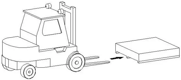
TRANSPORT & UNPACKING
Depending on the standard request, this lift and the hydraulic pump are protectedbytwo cartons with pallets. And the machine must be handled with a forklift withtheforks positioned as shown in the figure.
CAUTIO Once the packing material has been removed, checkthemachine for any sings of damage.
![]() WARNING Keep the packing materials out of the reach of childrenastheycan be a source of danger.
WARNING Keep the packing materials out of the reach of childrenastheycan be a source of danger.
Keep the packing for possible future transport.
SPECIFICATIONS
| Motor | 110 VAC at 60 Hz, 1 Ph, 2.95 hp ( 2.2 kW ) |
| Lifting Capacity | 6614 lbs ( 3000 kg ) |
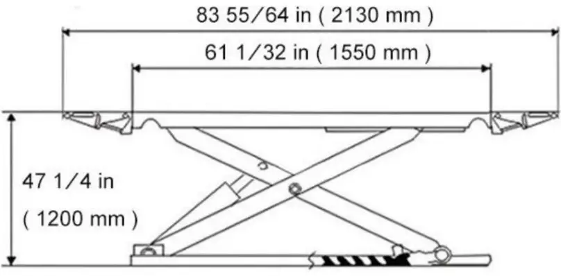
| Max Lifting Height | 47 1/4 in ( 1200 mm ) |
| Lowered Height | 4 21/64 in ( 110 mm ) |
| Lifting Time | 30 seconds |
| Air Supply | 87 – 116 psi ( 6 – 8 bar ) |
| Single Platform Length | 61 1/32 in ( 1550 mm ) |
| Single Platform Width | 20 55/64 in ( 530 mm ) |
| Width between Platforms | 32 1/2 in ( 800 mm ) |
| Overall Length (includes Ramps) | 83 55/64 in ( 2130 mm ) |
| Overall Width | 75 15/64 in ( 1860 mm ) |
| Product Weight | 1190.5 lbs ( 540 kg ) |

WORKING PLACE
Choose the place the machine is to be installed in compliance withcurrent work place safety regulations. The floor should not be brokenoruneven so that the machine will be stable and the platformcanmovefreely.
If the installation is out door, it must be protected by some kindof roofing against rain.
The following work environment conditions are applicable
- Relative humidity: from 30-95% without condensation.
- Temperature: 5-55℃.
WARNING The machine must not be operated in explosive atmospheres.
WORKPLACE REQUIREMENTS
Maximum machine space requirements are 3200X2000mmwithaminimum distance from walls as shown in the diagram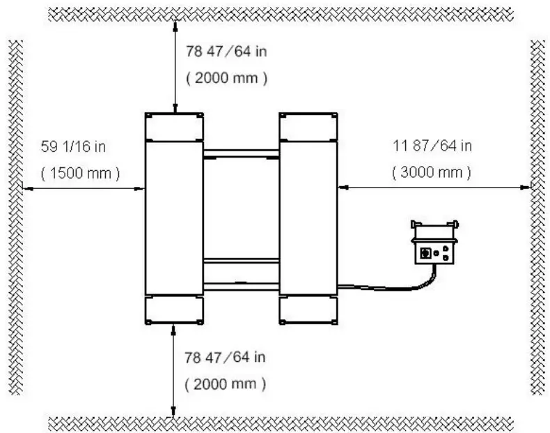
WARNING These measurements are also the machine working range. Persons other thanspecially trained and authorized operators are expressly forbidden to enter this area,
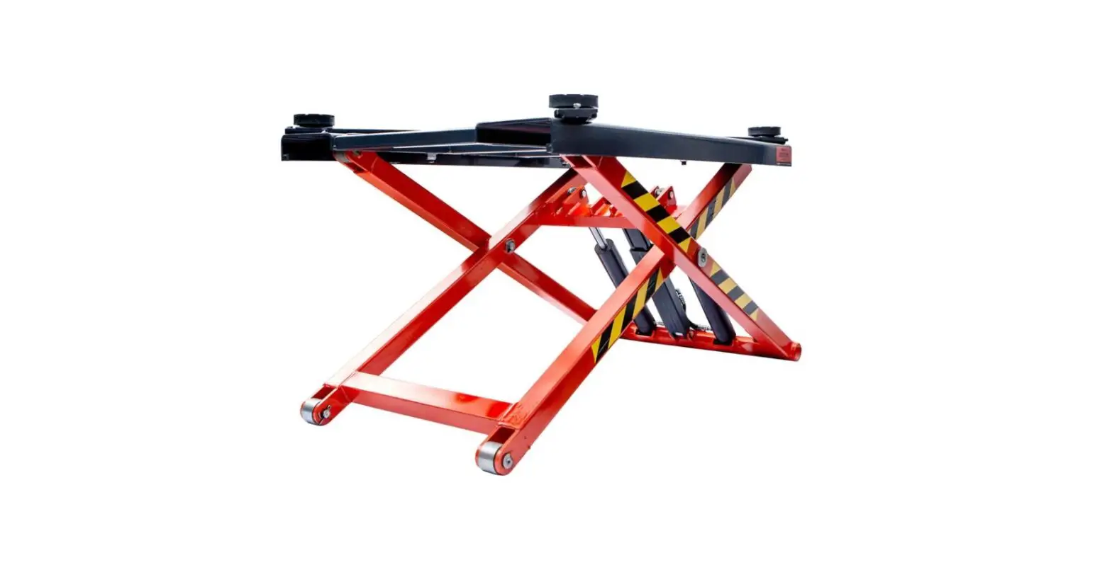
DESCRIPTION
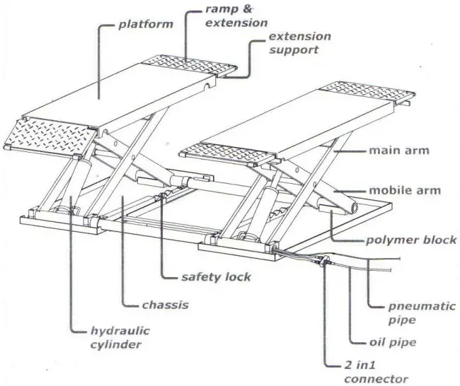
NOTE
It is main parts figure above. More detailed components and assembly please seeexploded view
DESCRIPTION
INSTALLATION
Connecting pipes
There are two pipes from the hydraulic pump as shown in the figure. (X) is a pneumatic pipe and used for the safety lock. (Y) is a hydraulic oil pipe andusedfor the hydraulic cylinders.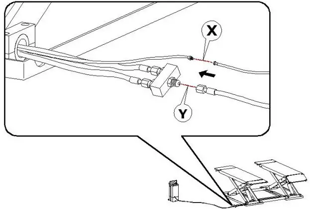
Enter hydraulic oil
Remove the motor box off, and then turn the oil cap anti-clockwise to opentheoil inlet. Fill in the hydraulic oil 30# from the oil inlet as shown in the figure.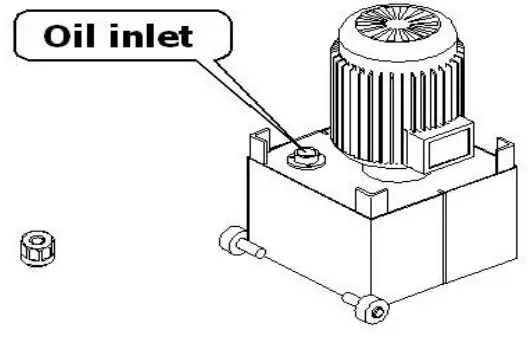
CAUTION
Use only given and eligible hydraulic oil, any other oil will cause severe damage to internal parts, such as the gear-pump, pipes and cylinders.
NOTE
- Make sure that there is sufficient oil in the tank when the machine working
- Do not overfill the oil tank, otherwise it may overflow when the oil warms upandexpands.
- Make sure that the oil tank cap is properly closed before working.
OPERATION
During all operations, keep hands and other parts of the body as far as possiblefrommoving parts of the machine. Necklace, bracelets and too large clothes, canbe dangerous for the operator.
When the power supplied, turn the POWER SWITCH clockwise while the machine is on standby and an INDICATOR will show.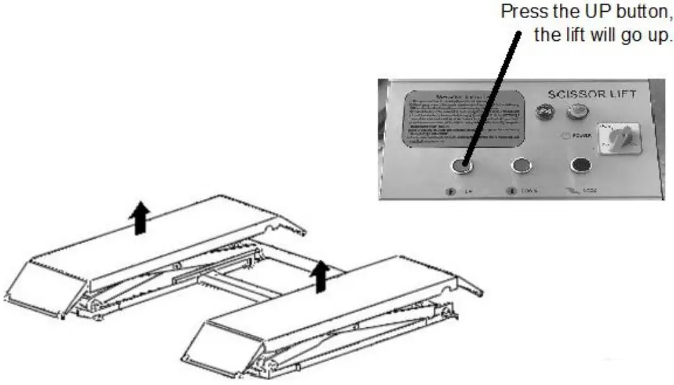
![]() WARNING
WARNING
When the lift is working (lifting a car), remember: Any personnel do not get in the lift and the car, it could result in severeinjury or death
![]() WARNING
WARNING
During all operations, keep hands and other parts of the body as far as possiblefrommoving parts of the machine. Necklace, bracelets and too large clothes, canbe dangerous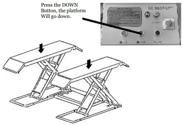
STORING
If the machine as to be stored for a long time you have to
- Go down the platforms and no heavy object on them.
- Disconnect the machine from all power sources. 96
- Grease all the parts that could be damaged if they dry out.
- Empty hydraulic oil reservoir and wrap the machine in a sheet of protectiveplastic to prevent dust from reaching the internal working parts. If the machine as to working again after a long storing period, it is necessary to:
- Put the oil into the reservoir again.
- Restore the electric connection.
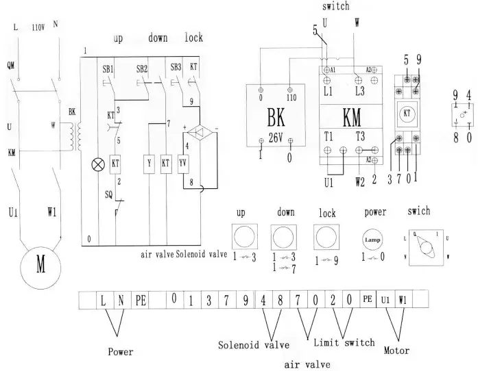
ELECTRIC SYSTEM
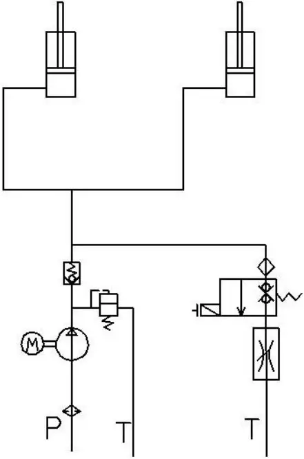
HYDRAULIC SYSTEM
STRUCTURE DIAGRAM
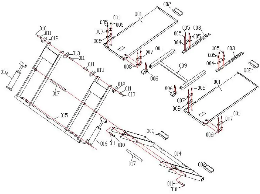
| Serial No. | Code | Name | Serial No. | Code | Name |
| 1 | 001 | base | 15 | 015 | Idle arm |
| 2 | 002 | Slide block | 16 | 016 | Oil cylinder |
| 3 | 003 | lock | 17 | 017 | shaft |
| 4 | 004 | Lock clamp | 18 | 018 | ramp |
| 5 | 005 | bolt | 19 | 019 | Support |
| 6 | 006 | Lock bend | 20 | 020 | platform |
| 7 | 007 | Up block | 21 | 021 | |
| 8 | 008 | Down block | 22 | 022 | |
| 9 | 009 | Lock cover | 23 | 023 | |
| 10 | 010 | waika | 24 | 024 | |
| 11 | 011 | shaft | 25 | 025 | |
| 12 | 012 | Slide block a | 26 | 026 | |
| 13 | 013 | Slide block b | 27 | 027 | |
| 14 | 014 | Drive arm | 28 | 028 |
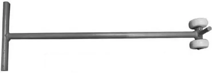
Packinglist
Mobile scissor lifter
| Serial number | Name | Quantity |
| 1 | A small round | 3 |
| 2 | Small round handle | 1 |
| 3 | Lead bridge plate | 4 |
| 4 | The rubber piece | 4 |
| 5 | Expansion screws | 6 |
| 6 | The lifting machine | 1 |
| 7 | Control cabinet | 1 |
| 8 | The trachea | 2 |
| 9 | The tubing | 2 |
| 10 | The instructions | 1 |


