msi MAG FORGE 110R Mid Tower Gaming PC Case
Contents hide
Accessories
Item | Name | Used for |
| Cable ties x5 | Cable management | |
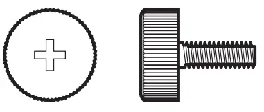 | Screw #6-32 10mm x2 | Securing drive tray |
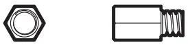 | Screw #6-32 6.5mm x4 | Motherboard Stud |
 | Screw M3 5mm x20 | Motherboard / SSD |
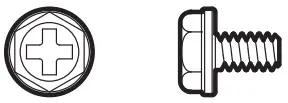 | Screw #6-32 6mm x6 | PSU / PCIe Card |
 | Screw #6-32 5mm x10 | 3.5” HDD |
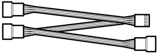 | 1 to 3 fan splitter cable x1 (MAG FORGE 112R only) | Connect 3 fans |
Specification
| Size | Mid-Tower |
| Fan LED Controller | 1 to 6 ARGB (3 pin) Control Board (MAG FORGE 111R / 112R) |
| Pre-Installed Fan | MAG FORGE 110R / 111R Rear: 1x 120 mm ARGB fanMAG FORGE 112R Rear: 1x 120 mm ARGB fan Front: 3x 120 mm ARGB fans |
| Material | Chassis: Steel (SPCC 0.5 mm) Right Side Panel: Steel Front Bezel: Plastic + MeshMAG FORGE 110R Left Side Panel: Transparent acrylicMAG FORGE 111R / 112R Left Side Panel: Tempered glass |
| Dust Filters | Top: Magnetic frame dust filter PVC mesh Bottom dust filter |
| Fan Support | Top: 2x 120 mm / 2x 140 mm Front: 3x 120 mm / 2x 140 mm Rear: 1x 120 mm |
| Drive Bays | 3 x 2.5” SSD mounting brackets (1 SSD tray & 2 with screw only) 2 x 3.5’’ + 2.5’’ combo HDD tray |
| Expansion Slots | Supports 7 expansion slots |
| 10 Panel | 1x LED switch button 2x USB 3.2 Gen1 Type A ports 1x Mic-in jack 1x Line-out jack 1x Reset button 1x Power button |
| Radiator Support | Top: 120/ 240 mm Front: 120 / 140 / 240 mm Rear: 120 mm |
| Clearance | CPU Cooler Height: Max 160mm (6.3 inch) Graphics Card Length: Max 330 mm (12.99 inch) PSU Length: Standard ATX 160mm (6.3 inch) Max 200 mm (7.87 inch) without 3.5” HDD tray installed |
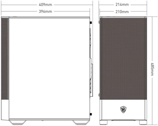
| Case Dimensions | 409(D) x 214(W) x 485(H) mm 16.1(D) x 8.43(W) x 19.09(H) inch |
| Motherboard Support | ATX/ M-ATX/ ITX |
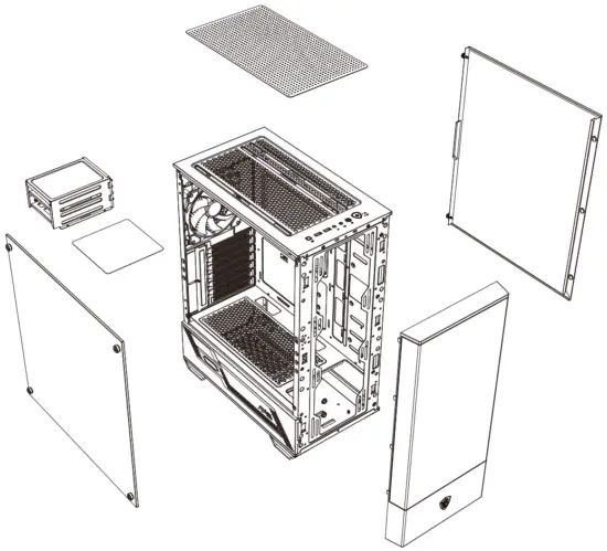
Case Features
Side & Front View
IO Panel
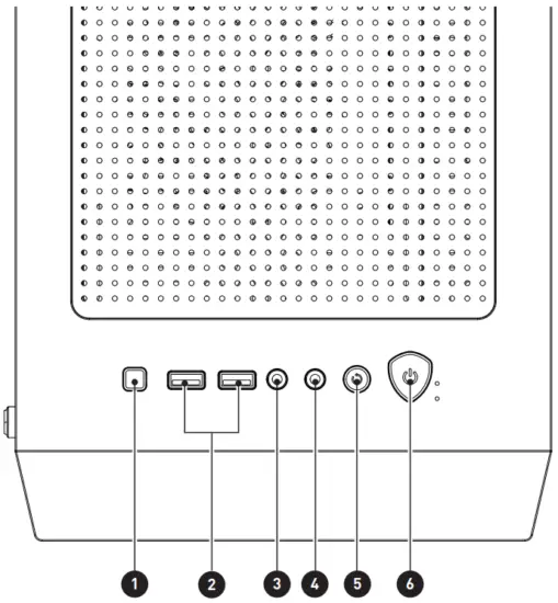
- LED switch button
- USB 3.2 Gen 1 Type-A
- Mic-in
- Line-out
- Reset button
- Power button
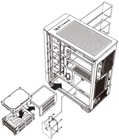
SSD, HDD Installation
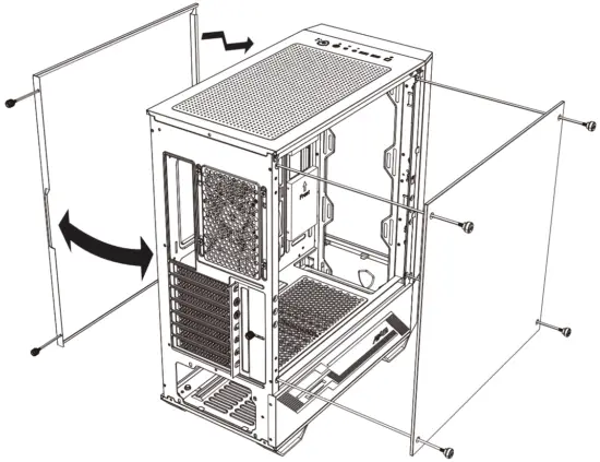
Opening the Left & Right Side Cover
Motherboard Installation
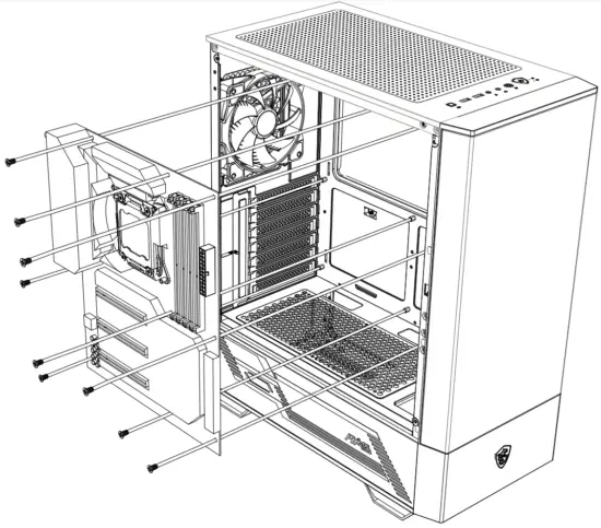
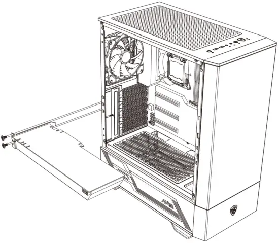
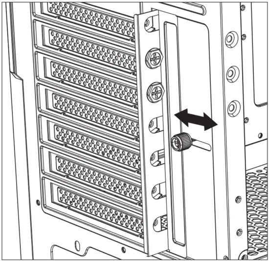
Graphics Card Installation
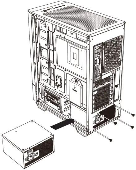
PSU Installation
Control Board Specification
| Dimensions (mm) | 50 x 30 |
| Support LED Type | DC5V Addressable RGB LED |
| Connectors | 1x LED switch connector 1x SATA power connector 1x MSI motherboard JRAINBOW connector 6x 3-pin ARGB LED connectors |
| ARGB Pin Definition | 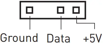 |
| LED Effects (1 short press the LED switch) | LED effect cycle:
|
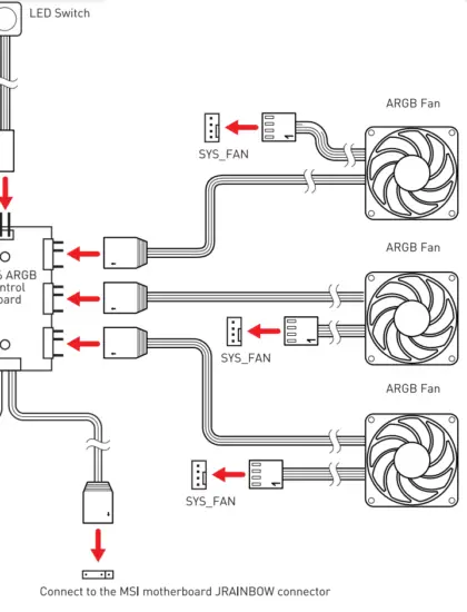
ARGB Fan Connection
LED switch control description:
- Short press the LED switch once to switch the LED effect
- Press and hold the LED switch for 3 seconds the LED flash white light once, and then into the MSI motherboard Mystic Light synchronization mode.
Short press once to back to the Hub control mode. - Press and hold the LED switch for 6 seconds to turn off the LED.
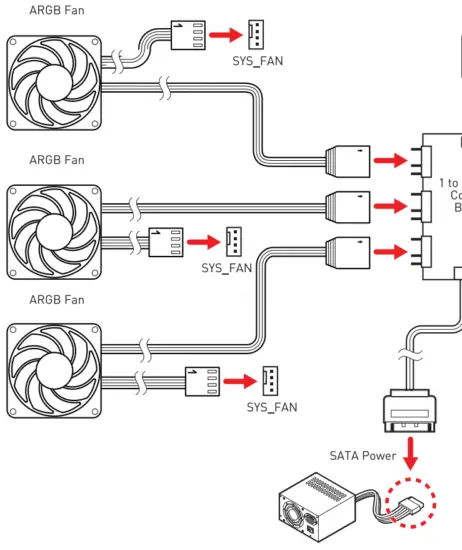
![]() Note
Note
- Support up to 128 LEDs, Exceeding this limit will lead to overheating, abnormal color or no light.
Note
Support up to 128 LEDs, Exceeding this limit will lead to overheating, abnormal color or no light. 128 LED


