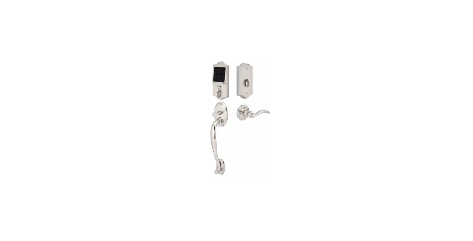
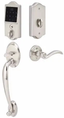
EMTEK EMTouch Classic Style Electronic Deadbolt Lock Sets
What’s in the Box
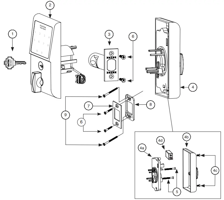
| ITEM NO. | DESCRIPTION | QTY. |
| 1 | Key | 2 |
| 2 | Outside Trim Plate Assembly | 1 |
| 3 | Deadbolt Latch Assembly 2 3/8” or 2 3/4” Backset | 1 |
| 4 | Inside Trim Plate Assembly | 1 |
| 4a | Inside Chassis | 1 |
| 4b | Inside Trim Plate | 1 |
| 4c | #8-32 x 3/8” Flat Head Machine Screw | 2 |
| 4d | 9V Alkaline Battery | 1 |
| 5 | #8-32 x 11/2” Flat Head Machine Screw | 2 |
| 6 | #8 x 3/4” Wood Screw | 4 |
| 7 | Strike Plate | 1 |
| 8 | Security Plate | 1 |
| 9 | #10 x 3” Wood Screw | 2 |
Preparation
Door Prep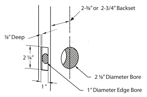
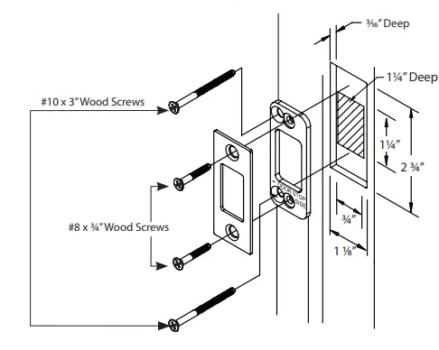
Door Jamb Prep
- Step 1: Fasten Security Plate using two #10 x 3” Wood Screws (item #9).
- Step 2: Fasten Strike Plate using two #8 x 3/4” Wood Screws (item #6).
How to Install
Install Latch
Fasten Latch using two #8 x 3/4” Wood Screws (item #6).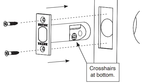
THE LATCH ASSEMBLY MUST BE ORIENTED AS SHOWN AND THE BOLT MUST BE IN THE RETRACTED POSITION FOR INSTALLATION.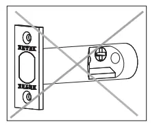
Remove Screws from Inside Trim Plate
Use a Phillips head screwdriver to remove screws (item #4c) shown below and detach Inside Trim Plate from the Inside Chassis.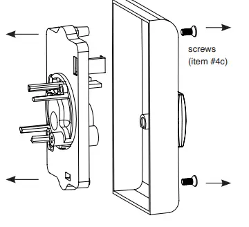
REMOVE INSIDE CHASSIS FROM TRIM PLATE BEFORE INSTALLING THE OUTSIDE TRIM. THUMBTURN MUST BE IN UNLOCKED POSITION.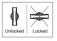
Install Outside Trim Plate Assembly
Position the Outside Trim Plate Assembly through the bore hole.
ONCE POSITIONED, OUTSIDE TRIM PLATE ASSEMBLY REQUIRES SUPPORT.
Install Inside Chassis
Step 1: Confirm the position of Flat Shaft.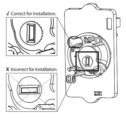
HOLE FOR FLAT SHAFT MUST BE IN VERTICAL POSITION FOR INSTALLATION.
Step 2: Feed the Wire Harness through Inside Chassis.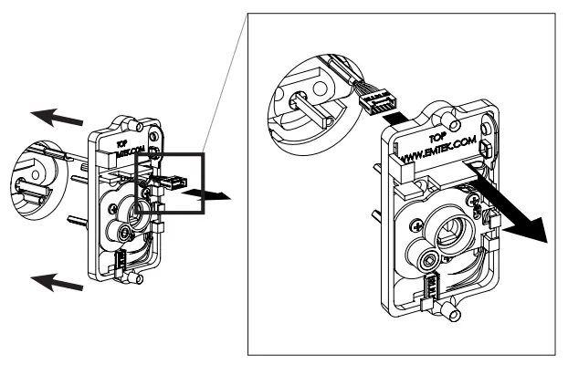
Step 3: Fasten Inside Chassis using two #8-32 x 11/2” Flat Head Machine Screws (item #5).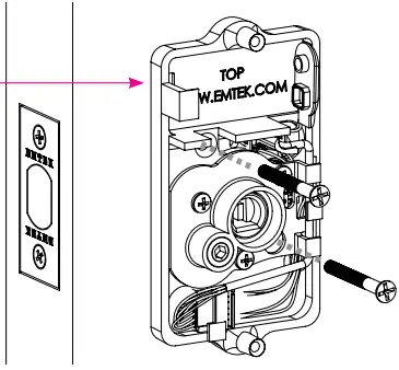
Step 4: Connect Wire Harness (A) and tuck Connectors as shown (B).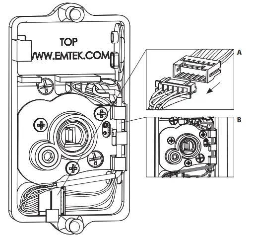
Step 5: Install Battery.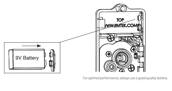
Install Inside Trim Plate
Fasten Inside Trim Plate using two #8-32 x 3/8” Flat Head Machine Screws (item #4c).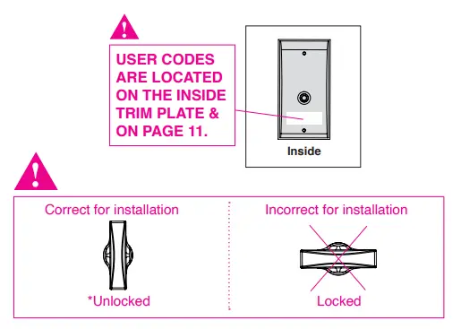
Unlocked position is required for installation and removal of the Inside Trim Plate Assembly.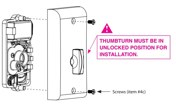
How to Use
Your Lock is Ready to Use
Your Emtek lock is shipped with two 4-digit user codes and a 6-digit programming code. These codes are randomly generated at the factory. (Turn to next page for Programming Instructions.)
To Unlock: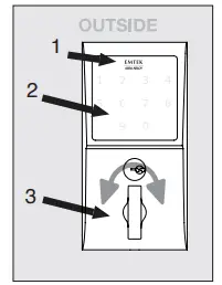
- 1. Press EMTEK key or touch 3 fingers across screen.
- Enter 4-digit user codes. (See sticker located on the inside trim plate or on page 11).
- Rotate Thumbturn.
To Lock: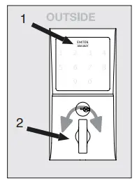
Option 1
- Press the EMTEK key.
- Rotate Thumbturn.
Option 2
- Touch 3 fingers across the screen.
- Enter 4-digit user codes. (See sticker located on the inside trim plate or on page 11).
- Rotate Thumbturn.
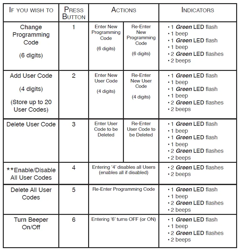
How to Program
Programming Your Lock
In order to perform each of the following six functions, the lock must first be placed in Programming Mode:
- Press and hold the EMTEK button for 3 seconds
- Yellow LED flashes, then remain solid*, number keys also illuminate
- Enter Programming Code
- Yellow LED flashes, then 1 beep
- Yellow LED remains solid (awaiting button press; see the following Table)
*If no input within 20 seconds, Yellow LED goes out, Red LED flashes and lock exits Programming Mode. **Also referred to as “vacation mode”. This command temporarily disables all user codes (metal key override will still work).
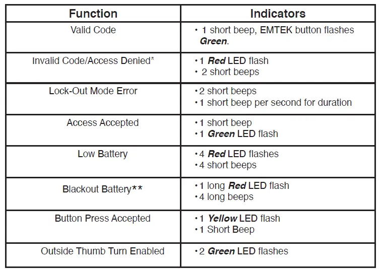
Keypad Operation – Beeper & LED Indicators
* If 3 consecutive incorrect codes are entered, the lock emits 4 short beeps and a flashing Red EMTEK button. The lock will not accept additional input for 20 seconds (20 beeps). When the next valid code is entered the lock will beep quickly 5 times to alert of the incorrect codes. ** Battery voltage has dropped too low; keypad will be disabled but metal key override will still work.
Restoring the Lock to Factory Default Setting
This procedure clears the lock of all users and restores the Programming Code and 2 User Codes shipped with the lock.
- Press and hold EMTEK button for 3 seconds.
- Enter “000000”
- After 2 beeps and 2 Green LED Flash, remove power (disconnect 9V battery) from Lock.
- After 5 seconds, restore power (reconnect 9V battery)
- Confirm by 2 beeps and 2 Green LED Flash
U.S. patents:
8,176,761
8,141,400
Canadian patents:
2,698,041
2,789,278
2,789,280
Emtek Products
Tel: 800-356-2741 • 626-961-0413
Fax: 800-577-5771 • 626-336-2812
emtek.com
Copyright © Emtek Products, ASSA ABLOY Residential Group Inc. DBA Emtek Products, 2021 Reproduction in whole or in part without the express written permission of Emtek Products is prohibited.


