![]()
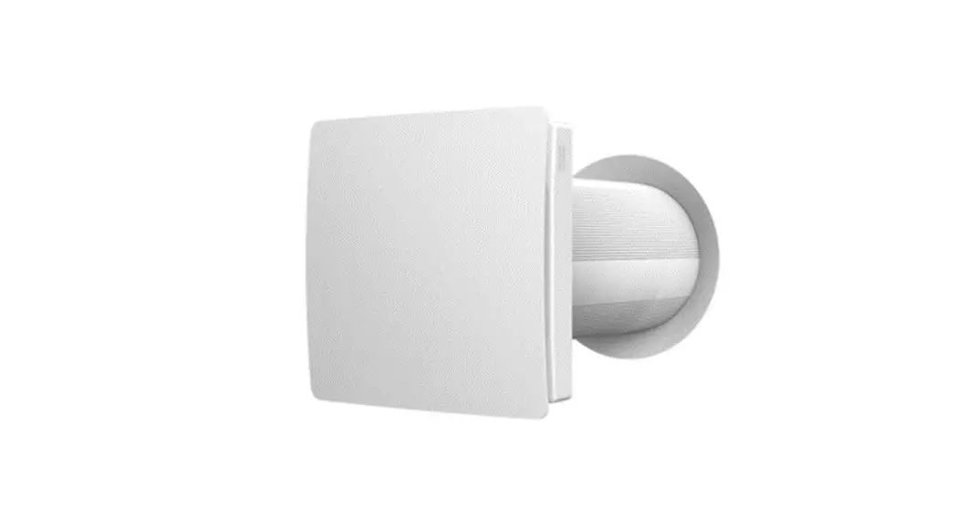
IV50G1.0
Heat Recovery Ventilator Instruction Manual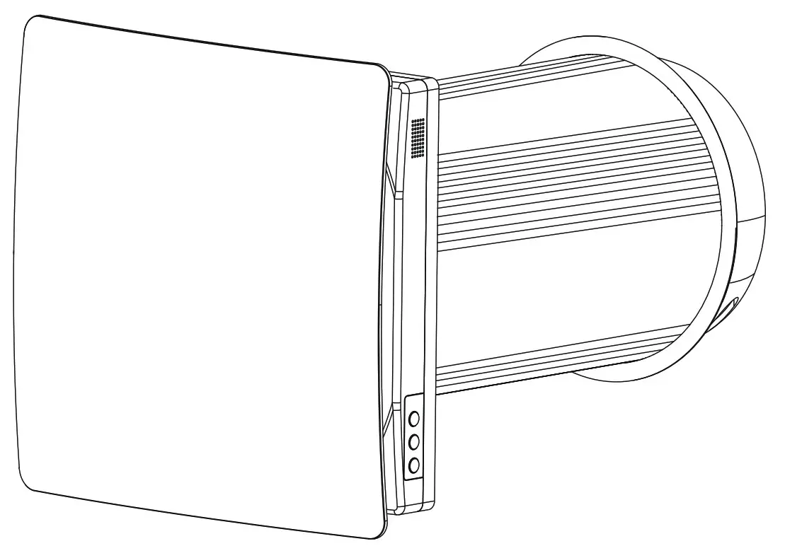
Operation Instruction for the user and the qualified installer
SAFTY REQUIREMENTS
- Read the user’s manual carefully before the operation and installation of the heat recovery ventilator IV50G1.0
- Installation and operation of the ventilator shall be performed in accordance with the present user’ s manual as well as the provisions of all the applicable local and national construction, electrical and technical codes and standards.
- The warnings contained in the present user’s manual must be considered seriously since they contain vital personal safety information.
- Failure to follow the safety regulations may result in an injury or ventilator damage.
- Read the manual carefully and keep it as long as you use the ventilator.
- While transferring the ventilator control the user’ s manual must be turned over to the receiving operator.
Symbol legend used in the manual:
| WARNING! | |
| DO NOT! |
VENTILATOR MOUNTING SAFETY PRECAUTIONS
| The ventilator must be disconnected from the power supply prior to every installation or repair operation. | |
| The ventilator must not be operated outside the temperature range stated in the user’s manual or in aggressive or explosive environ-ments. | |
| Do not position any heating devices or other equipment in close proximity to the ventilator power cord. | |
| Do not use damaged equipment or conductors to connect the ventilator to power mains. | |
| While installing the ventilator follow the safety regulations specific to the use of electric tools. | |
| Unpack the ventilator with care. | |
| Use the ventilator only as intended by the manufacturer. |
VENTILATOR OPERATING SAFETY PRECAUTIONSPRECAUTIONS
| Do not touch the controller or the remote control with wet hands. Do not carry out the ventilator maintenance with wet hands. | |
| Do not let children operate the ventilator. | |
| Do not wash the ventilator with water. Protect the ventilator electric parts from water ingress. | |
| Do not block the air duct when the ventilator is on. | |
| Disconnect the ventilator from power supply before maintenance. | |
| Do not damage the power cable while operating the ventilator. Do not put any objects on the power cable. | |
| Keep explosive and inflammable products away of the ventilator. | |
| Do not open the operating ventilator. | |
| In case of unusual sounds, or smoke, disconnect the ventilator from power supply and contact the service centre. | |
| Do not let air flow from the ventilator be directed to the open flame devices or candles. |
INTRODUCTION
This user’s manual includes technical description operation, installation and mounting guidelines, technical data for the heat recovery ventilator IV50G1.0
USE
- The ventilator is designed to arrange permanent controllable air exchange in apartments, villas, hotels, cafes and other domestic and public buildings.The ventilator is equipped with a ceramic heat exchanger that enables supply of fresh air and extract air with heat energy recovery
- The ventilator is designed for through-the-wall mounting. The telescopic ventilator design enables its installation in the walls from 250 mm to 500 mm thickness for the ventlator IV50G1.0 ‘The ventilator is rated for continuous operation always connected to power mains.
- Transported air must not contain any flammable or explosive mixtures, evaporation of chemicals, coarse dust, soot and oil particles, sticky substances, fibrous materials, pathogens or any other harmful substances.
![]() THE VENTILATION NOT INTENDED TO BE USED BY CHILDRER PHYSICALLY OR MENTALLY DISABLED PERSONS, PERSONS WITH SENSORY DISORDER, PERSONS WITH NO APPROPRIATE QUAUFICATIOH. INSTALLATION AND CONNECTION OPERATIONS MUST BE PERFORMED ONLY BY PROPERLY QUALIFIED PERSONNEL AFTER THE APPROPRIATE SAFETY BRIEFING.THE VENTILATOR INSTALLATION SITES MUST PREVENT ACCESS BY UNATTENDED CHILDREN.
THE VENTILATION NOT INTENDED TO BE USED BY CHILDRER PHYSICALLY OR MENTALLY DISABLED PERSONS, PERSONS WITH SENSORY DISORDER, PERSONS WITH NO APPROPRIATE QUAUFICATIOH. INSTALLATION AND CONNECTION OPERATIONS MUST BE PERFORMED ONLY BY PROPERLY QUALIFIED PERSONNEL AFTER THE APPROPRIATE SAFETY BRIEFING.THE VENTILATOR INSTALLATION SITES MUST PREVENT ACCESS BY UNATTENDED CHILDREN.
DELIVERY SET
| Ventilator | 1 item |
| Fastening set | 1 item |
| Remote controller | 1 item |
| User’s manual | 1 item |
| Packing box | 1 item |
MAIN TECHNICAL PARAMETERS
- The ventilator is designed for indoor application with the ambient temperature ranging from -20°C (-4°F) to +50°C(122°F) and relative humidity up to 80%.
- The ventilator is classified as a class I electric appliance.
- Ingress Protection UP) rating from solid objects and liquids IPX2.
- The ventilator design is regularly improved, so some models may slightly differ from those ones described in this manual.
VENTILATOR OVERALL DIMENSIONS ( MM )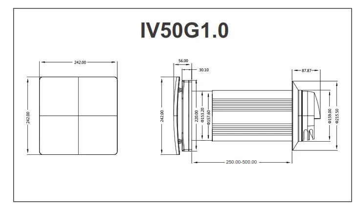
| Speed | I | II | III | |||
| Voltage, 50-60 Hz [V] | 100-240 | |||||
| 1.8 | 4. | 7.0 | ||||
| Ventilator Total Power [W] | ||||||
| Max. Ventilator Current [A] | 0.019 | 0.034 | 0.0533 | |||
| Max. Air Capacity [m3/h] (CFM) | 48(28) | 54(32) | 60(35) | |||
| RPM [min] | 651 | 956 | 1261 | |||
| -20°C(-4°F) to +50°C(122°F) | ||||||
| Max. Transported Air Temperature [°C]/(°F) | ||||||
| Heat Exchange Efficiency | up to 90% | |||||
| Heat Exchanger core | Ceramic | |||||
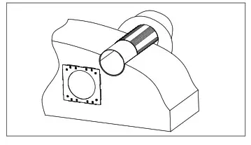
DESIGN AND OPERATING
The ventilator consists of the telescopic air duct with adjustable length regulated by position of the inner air duct inside the outer air duct, the ventilation unit and the ventilation hood.
Two filters and the ceramic core are located inside the inner duct The filters are designed to purify supply air and prevent foreign object ingress to the heat exchanger and the
fan. The ceramic heat exchanger extract air heat energy to warm up or cool down supply airflow.
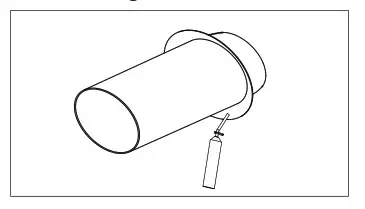
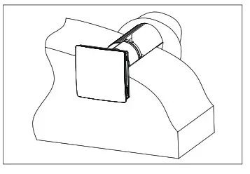
The heat exchanger is equipped with a pull cord inside to facilitate its withdrawal from the ventilator. The heat exchanger is installed on an insulation material used as a sealant as well. The ventilator must be installed on inner side of the wall. ‘ The ventilation hood must be installed on outer side of the wall to prevent ingress of water and other objects to the ventilator.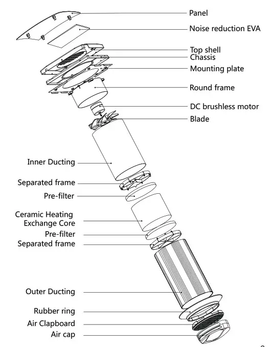
VENTILATOR OPERATING MODES
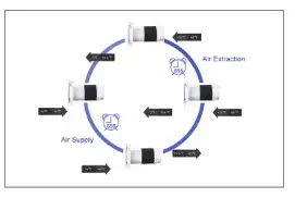
The ventilator has three ventilation modes: Fresh Air Mode the ventilator supplies fresh air Exhaust Mode the ventilator operates in exhaust mode Cycle Mode the ventilator operates in reversible mode with heat and humidity recovery
In cycle mode the ventilator operates in two cycles, 65 seconds each. Cycle I. Warm stale air is extracted from the room. As it flows through the heat exchanger, it heat and moisturizes the exchanger, transferring up to 90% . In 65 seconds as the ceramic exchanger gets warmed the ventilator is switched to supply mode. Cycle II. Fresh intake air from outside flows through the ceramic exchanger and absorbs moisture and heats up to the room temperature. In 65 seconds as the ceramic regenerator gets cooled down, the ventilator is switched into extract mode and the cycle is renewed.
 MOUNTING AND SET-UP
![]() READ THE USER’ S MANUAL PRIOR TO MOUNTING THE VENTILATOR
READ THE USER’ S MANUAL PRIOR TO MOUNTING THE VENTILATOR
![]()
![]() CAUTION! THE VENTILATOR MUST NOT BE INSTALLED IN SITES WHERE THE AIR DUCT MAY BE CLOGGED BY THE BLINDS, CURTAINS, DRAPES, ETC, TO PREVENT THE ROOM DUST DEPOSITION AND ACCUMULATION. ALSO, CURTAINS MIGHT OBSTRUCT NORMAL AIRFLOW IN THE ROOM, THUS RENDERING VENTILATOR OPERATION NOT EFFICIENT.
CAUTION! THE VENTILATOR MUST NOT BE INSTALLED IN SITES WHERE THE AIR DUCT MAY BE CLOGGED BY THE BLINDS, CURTAINS, DRAPES, ETC, TO PREVENT THE ROOM DUST DEPOSITION AND ACCUMULATION. ALSO, CURTAINS MIGHT OBSTRUCT NORMAL AIRFLOW IN THE ROOM, THUS RENDERING VENTILATOR OPERATION NOT EFFICIENT.
VENTILATOR MOUNTING
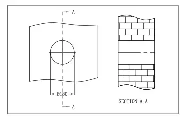
- Prepare a round hole through in the wall. The hole size is shown below.

- Assembly inner duct and outer duct together to adapt to the thinkness of wall. Cutting the duct adapt to the thin wall. Paste wateproof sealing glue on the inner side of rubber ring, show as below image.

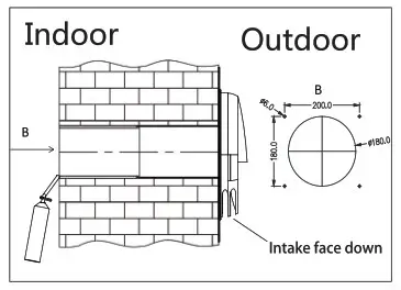
- Through the wall hole from indoor, and pull back the duct to make the inner side rubber ring cling to the outside wall. Fill the gap between the wall and duct with foam glue(Using waterproof sealing glue for the gap close to indoor to against rainwater). The inner duct should parallel with indoor wall surface.

- Paste the location sticker on the wall surface. Pay Attention to the direction to make sure the circle on location sticker and duct to be concentric. Marking the drilling hole site and remove the location sticker. Drilling 4*6mm hole on the marking place and put in the rubber plug(as pack accessories)
 VENTILATOR MOUNTING
 - Install the filter, the ceramic exchanger core, another filter and the air flow rectifier in consecutive order inside the telescopic air duct.

- Install the ventilation unit on the mounting plate. The ventilation unit is fixed with magnets.

 VENTILATOR MOUNTING
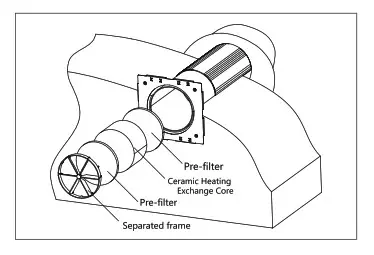
CONNECTION TO POWER MAINS![]() DISCONNECT THE VENTILATION FROM TOWER MAINS PRIOR TO ANY ELECTRIC INSTALLATION OPERATIONS.CONNECT THE VENTILATOR CORRECTLY WITH A ROUNDED TERMINAL ANY INTERNAL ‘CONNECTION MODIFICATIONS ARE NOT ‘ALLOWED AND RESULT IN WARRANTY
DISCONNECT THE VENTILATION FROM TOWER MAINS PRIOR TO ANY ELECTRIC INSTALLATION OPERATIONS.CONNECT THE VENTILATOR CORRECTLY WITH A ROUNDED TERMINAL ANY INTERNAL ‘CONNECTION MODIFICATIONS ARE NOT ‘ALLOWED AND RESULT IN WARRANTY
The ventilator is rated for connection to single-phase AC90-240 V/ 50-60 Hz power mains. Connect the ventilator to the socket directly.
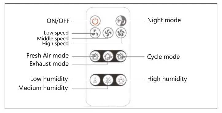
REMOTE CONTROL FUNCTION DESCRIPTION
Electrical parameter
- Operating Voltage : DC3V(CR2025Button battery )
- Emission current<5mA
- Sleep standby current<10pA
- Effective control distance : partition
- walls>15m, open>30m
- Carrier frequency: 433.92MHz
OPERATION WITH THE CONTROL BUTTONS ON THE VENTILATOR CASING
- Turning the ventilator ON. Setting operation speed.
| Press with a beep. | Low speed. | ||
| Press with two beeps. | Middle speed. | ||
| Press with three beeps. | High speed. | ||
| ON/OFF | |||
2. Turning the ventilator OFF.
REMOTE MATCHING GUIDANCE:
Inserting a pin into the holeand gently press the switch until there is a “beep” sound heard. Then press any button on the remote until there is a “beep beep” sound heard.Fan turn on working, matching successfully
- Turning ventilator ON/OFF II I

Turning the ventilator OFF. - Night Mode

ON/OFF
If Night Mode is activated, the ventilator switches to the first speed in the night, when the light is turned off. Activation of the night mode is confirmed by a long sound signal. Exiting the night mode is confirmed by a short sound signal.
3. Speed setting
| Low speed. | |
| Middle speed. | |
| High speed. |
4. Operation mode
| Fresh Air mode. Air is supplied to the room at a set speed regardless of CN7 jumper. | |
| Exhaust mode. Air is extracted (factory setting) at a selected speed. | |
| Cycle mode. The ventilator operates 65 seconds in Supply mode and then 65 seconds in Exhaust mode with heat regeneration. |
5. Humidity control. Humidity control is possible only in Regeneration mode.
| Setting humidity threshold -50% | |
| Setting humidity threshold -60% | |
| Setting humidity threshold -70% |
HUMIDITY CONTROL MAYBE ACTIVATED WITH THE REMOTE CONTROL ONLY!
MAINTENANCE![]() DISCONNECT THE VENTILATOR FROM POWER.
DISCONNECT THE VENTILATOR FROM POWER.
SUPPLY PRIOR TO ANY MAINTENCE OPERATION
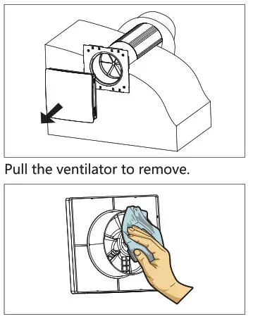
Maintenance of the ventilator means regular cleaning of the ventilator surfaces of dust and cleaning or replacement of the filters.
- Fan maintenance (once per year).
 Clean the impeller blades. To remove dust use a soft brush, doth or a vacuum cleaner. Do not use water, abrasive detergents, solvents, sharp objects. The impeller blades must be cleaned once in year.
 - Regenerator and filter maintenance (4 times per year).
 Remove the air flow rectifier. Remove the filter in front of the regenerator. Pull the exchanger cord to remove from the air duct Be careful while pulling the Excharger to avoid damage. Remove the filter after the exchanger
 Clean the impeller blades. To remove dust use a soft brush, doth or a vacuum cleaner. Do not use water, abrasive detergents, solvents, sharp objects. The impeller blades must be cleaned once in year.
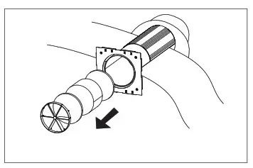 Remove the air flow rectifier. Remove the filter in front of the regenerator. Pull the exchanger cord to remove from the air duct Be careful while pulling the Excharger to avoid damage. Remove the filter after the exchanger
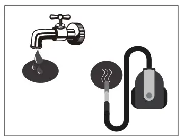 Clean the filter as often as it gets dirty, but at least 3-4 times a year. Clean the filters, let them get dry and install the dry filters inside the air duct Vacuum cleaning is allowed. The filter rated service life is 3 years. Contact the Seller for spare filters.
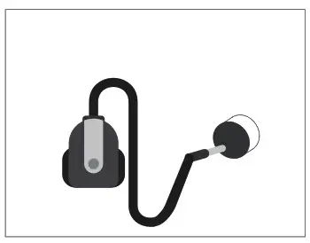
Even regular technical maintenance may not completely prevent dirt accumulation on the regenerator assemblies.
Subject the exchanger to regular cleaning to ensure high heat exchange efficiency.
Clean the exchanger with a vacuum cleaner at least once in a year.
TROUBLESHOOTING
Possible faults and troubleshooting
| Fault | Possible reasons | Fault handling |
| The fan does not start up during the ventilator start-up. | No power supply. | Make sure that the ventilator is properly connected to the Power mains and make any corrections, if necessary. |
| Motor is jammed, the impellers are clogged. | Turn the ventilator off. Troubleshoot the motor jam and the impeller dogging. Clean the blades. Restart the ventilator. | |
| Automatic switch tripping following the ventilator turning on. | Overcurrent resulted from short circuit in the electric circuit. | Turn the ventilator off Contact the service center. |
| Low air flow. | Low set fan speed. | Set higher speed. |
| The filter, the fan or the exchanger are dirty. | Clean or replace the filter, clean the fan and the exchanger. For the exchanger and the filter maintenance, refer to page 15. | |
| The ventilator generates sound signals. | The operating time meter for filter replacement is activated. | For the exchanger and the filter maintenance, refer to page 16. |
| High noise, vibration. | The impeller is soiled. | Clean the impeller. |
| Loose screw connection of the ventilator casing or the ventilation hood. | Tighten the screws of the ventilator or the outer ventilation hood. |
STORAGE AND TRANSPORTATION RULES
Store the ventilator In the manufacturers original packing box in a dry Storage environment must not contain aggressive vapours and chemical mixtures provoking corrosion, insulation and sealing deformation. Use hoist machinery for handling and storage operations to prevent the ventilator damage in consequence of failing or excessive oscillation. Fulfil the handling requirements applicable for the applicable freight type. Transportation with any vehicle type is allowed provided that the ventilator is protected against mechanical and weather damage. Avoid any mechanical shocks and strokes during handling operations.
Arctica Solar
PO Box 3541,
Huntington Beach, CA 92647
P: (714) – 698-9779
E: [email protected]


