Bard QW 920-0032 Energy Recovery Ventilator
General Notes
- Revised and/or additional pages may be issued from time to time.
- A complete and current manual consists of pages shown in the following contents section.
Important
- Contact the installing and/or local Bard distributor for all parts requirements. Make sure to have the complete model and serial number available from the unit rating plates.
FUNCTIONAL and CABINET COMPONENTS
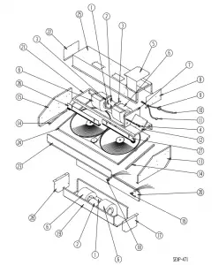
Drawing No. | Part No | Description | 920-0032 | 920-0531 |
1 | 8552-001 | Blower Motor Capacitor | 2 | 2 |
2 | 8101-024 | Blower Motor | 2 | 2 |
3 | 128-018 | Motor Mount | 4 | 4 |
4 | S910-1637 | Terminal Block Assembly | 1 | 1 |
5 | 132-147 | Control Panel Cover | 1 | 1 |
6 | Blower Housing | See Blower Housing Drawing | 2 | 2 |
7 | 520-307 | Upper Blower Box Partition | 1 | 1 |
8 | 100-332 | Right End Upper Blower Box | 1 | 1 |
9 | 3000-1059 | Wire Harness | 1 | 1 |
10 | 3000-1048 | Wire Harness | 1 | 1 |
11 | 3000-1147 | Wire Harness | 1 | 1 |
12 | 116-193 | Control Panel | 1 | 1 |
13 | 100X331 | Right End | 1 | 1 |
14 | 104-989 | Side Angle | 2 | 1 |
15 | 100Y331 | Left End | 1 | 1 |
16 | 3000-1061 | Wire Harness | 1 | 1 |
17 | 500X278 500X395 | Right End Lower Blower Box Right End Assembly | 1 | 1 |
18 | 3000-1060 | Wire Harness | 1 | 1 |
19 | 538-084 538-152 | Lower Blower Box Assembly Wrapper Assembly | 1 | 1 |
20 | 520-318 | Lower Partition Assembly | 1 | 1 |
21 | 106-188 | Top Assembly | 1 | 1 |
22 | 500-333 500Y395 | Left End Upper Blower Box Left End Assembly | 1 | 1 |
23 | 114-111 | Front Fill | 1 | 1 |
24 | 5070-036 | Cassette – Complete | 1 | 1 |
25 | 538-183 | Upper Blower Box Assembly | 1 | 1 |
26 | 139-110 | Left Seal Assembly | 1 | 1 |
27 | 139-111 | Right Seal Assembly | ||
28 | 500Y278 | Left End Lower Blower Box | 1 | 1 |
NS | 3000-1073 | Wire Harness | 1 | 1 |
NS | 538-151 | Exhaust Duct Assembly | 1 | 1 |
NS | 4056-157 | Wiring Diagram | 1 | 1 |
NS | 8407-077 | Stepdown Transformer 277V/230V 1.0KVA | 1 | |
NS | 8614-058 | 2-Pole Enclosed Fuse Holder | 1 | |
NS | 8614-047 | 3.2A Class CC Fuse | 2 |
NS = Not Shown
CASSETTE COMPONENTS
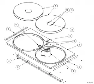
Drawing No | Part No | Description | 920-0032 |
1 | 539-168 | Cassette Plate Assembly | 1 |
2 | 104-1127 | Right Support Angle | 1 |
3 | 104-1128 | Left Support Angle | 1 |
4 | S140-288 | Support Bar Assembly | 1 |
5 | 5070-043 | Cassette Wheel | 2 |
6 | 5501-019 | Pulley | 1 |
7 | 8101-016 | Motor | 1 |
8 | 142-104 | Hub Cover | 2 |
9 | 1912-012 | Wheel Shaft | 2 |
10 | 8620-196 | Drive Belt & Pulley Kit | 2 |
11 | S5070-047 | Center Block Assembly | 1 |
12 | 1012-164 | Machine Screw | 4 |
13 | 8611-111 | Nylon Spacer | 4 |
NS | 5070-052 | 3/4″ Bearing/Hub Assembly | 2 |
NS | 8620-204➀ | Bearing/Hub, Shaft & Hardware Kit | 2 |
NS | 8620-205 ➁ | Shaft & Hardware Kit | 2 |
NS = Not Shown
➀ = Contains Item #’s 8, 9, 12, 13 and “NS” Bearing + Additional Hardware
➁ = Contains Item #’s 8, 9, 12, 13 + Additional Hardware
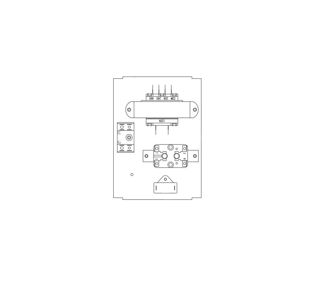
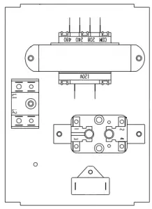
CONTROL PANEL
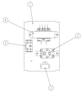
Drawing No. | Part No. | Description | 920-0032 |
1 | 116-193 | Control Panel | 1 |
2 | 8201-008 | Blower Relay | 1 |
3 | 8552-100 | Cassette Motor Capacitor | 1 |
4 | 8407-043 | Transformer | 1 |
5 | 8607-017 | Terminal Block | 1 |
NS | 8406-101 | Speed Switch | 1 |
NS = Not Shown
BLOWER ASSEMBLY

Drawing No. | Part No. | Description | 920-0032 |
1 | 5152-078 | Blower Wheel | 1 |
2 | 144-188 | Inlet Ring | 2 |
3 | 151-119 | Blower Housing | 1 |