Bard I-TEC Economizer Ventilator System Instruction Manual
Performance and Application Data
Summer Cooling Performance (Indoor Design Conditions 75°DB/62°WB)
| Ambient O.D. | VENTILATION RATE 450 CFM 65% EFFICIENCY | VENTILATION RATE 375 CFM 66% EFFICIENCY | VENTILATION RATE 300 CFM 67% EFFICIENCY | ||||||||||||||||
| DB/WB | F | VLT | VLS | VLL | HRT | HRS | HRL | VLT | VLS | VLL | HRT | HRS | HRL | VLT | VLS | VLL | HRT | HRS | HRL |
| 105 | 75 | 21465 | 14580 | 6884 | 13952 | 9477 | 4475 | 17887 | 12150 | 5737 | 11805 | 8018 | 3786 | 14310 | 9720 | 4590 | 9587 | 6512 | 3075 |
| 70 | 14580 | 14580 | 0 | 9477 | 9477 | 0 | 12150 | 12150 | 0 | 8018 | 8018 | 0 | 9720 | 9720 | 0 | 6512 | 6512 | 0 | |
| 65 | 14580 | 14580 | 0 | 9477 | 9477 | 0 | 12150 | 12150 | 0 | 8018 | 8018 | 0 | 9720 | 9720 | 0 | 6512 | 6512 | 0 | |
| 100 | 80 | 31590 | 12150 | 19440 | 20533 | 7897 | 12635 | 26325 | 10125 | 16200 | 17374 | 6682 | 10692 | 21060 | 8100 | 12960 | 14110 | 5427 | 8683 |
| 75 | 21465 | 12150 | 9314 | 13952 | 7897 | 6054 | 17887 | 10125 | 7762 | 11805 | 6682 | 5123 | 14310 | 8100 | 6210 | 9587 | 5427 | 4160 | |
| 70 | 12352 | 12150 | 202 | 8029 | 7897 | 131 | 10293 | 10125 | 168 | 6793 | 6682 | 111 | 8235 | 8100 | 135 | 5517 | 5427 | 90 | |
| 65 | 12150 | 12150 | 0 | 7897 | 7897 | 0 | 10125 | 10125 | 0 | 6682 | 6682 | 0 | 8100 | 8100 | 0 | 5427 | 5427 | 0 | |
| 60 | 12150 | 12150 | 0 | 7897 | 7897 | 0 | 10125 | 10125 | 0 | 6682 | 6682 | 0 | 8100 | 8100 | 0 | 5427 | 5427 | 0 | |
| 95 | 80 | 31590 | 9720 | 21870 | 20533 | 6318 | 14215 | 26325 | 8100 | 18225 | 17374 | 5345 | 12028 | 21060 | 6480 | 14580 | 14110 | 4341 | 9768 |
| 75 | 21465 | 9720 | 11744 | 13952 | 6318 | 7634 | 17887 | 8100 | 9787 | 11805 | 5345 | 6459 | 14310 | 6480 | 7830 | 9587 | 4341 | 5246 | |
| 70 | 12352 | 9720 | 2632 | 8029 | 6318 | 1711 | 10293 | 8100 | 2193 | 6793 | 5345 | 1447 | 8235 | 6480 | 1755 | 5517 | 4341 | 1175 | |
| 65 | 9720 | 9720 | 0 | 6318 | 6318 | 0 | 8100 | 8100 | 0 | 5345 | 5345 | 0 | 6480 | 6480 | 0 | 4341 | 4341 | 0 | |
| 60 | 9720 | 9720 | 0 | 6318 | 6318 | 0 | 8100 | 8100 | 0 | 5345 | 5345 | 0 | 6480 | 6480 | 0 | 4341 | 4341 | 0 | |
| 90 | 80 | 31590 | 7290 | 24300 | 20533 | 4738 | 15794 | 26325 | 6075 | 20250 | 17374 | 4009 | 13365 | 21060 | 4860 | 16200 | 14110 | 3256 | 10854 |
| 75 | 21465 | 7290 | 14175 | 13952 | 4738 | 9213 | 17887 | 6075 | 11812 | 11805 | 4009 | 7796 | 14310 | 4860 | 9450 | 9587 | 3256 | 6331 | |
| 70 | 12352 | 7290 | 5062 | 8029 | 4738 | 3290 | 10293 | 6075 | 4218 | 6793 | 4009 | 2784 | 8235 | 4860 | 3375 | 5517 | 3256 | 2261 | |
| 65 | 7290 | 7290 | 0 | 4738 | 4738 | 0 | 6075 | 6075 | 0 | 4009 | 4009 | 0 | 4860 | 4860 | 0 | 3256 | 3256 | 0 | |
| 60 | 7290 | 7290 | 0 | 4738 | 4738 | 0 | 6075 | 6075 | 0 | 4009 | 4009 | 0 | 4860 | 4860 | 0 | 3256 | 3256 | 0 | |
| 85 | 80 | 31590 | 4860 | 26730 | 20533 | 3159 | 17374 | 26325 | 4050 | 22275 | 17374 | 2672 | 14701 | 21060 | 3240 | 17820 | 14110 | 2170 | 11939 |
| 75 | 21465 | 4860 | 16605 | 13952 | 3159 | 10793 | 17887 | 4050 | 13837 | 11805 | 2672 | 9132 | 14310 | 3240 | 11070 | 9587 | 2170 | 7416 | |
| 70 | 12352 | 4860 | 7492 | 8029 | 3159 | 4870 | 10293 | 4050 | 6243 | 6793 | 2672 | 4120 | 8235 | 3240 | 4995 | 5517 | 2170 | 3346 | |
| 65 | 4860 | 4860 | 0 | 3159 | 3159 | 0 | 4050 | 4050 | 0 | 2672 | 2672 | 0 | 3240 | 3240 | 0 | 2170 | 2170 | 0 | |
| 60 | 4860 | 4860 | 0 | 3159 | 3159 | 0 | 4050 | 4050 | 0 | 2672 | 2672 | 0 | 3240 | 3240 | 0 | 2170 | 2170 | 0 | |
| 80 | 75 | 21465 | 2430 | 19035 | 13952 | 1579 | 12372 | 17887 | 2025 | 15862 | 11805 | 1336 | 10469 | 14310 | 1620 | 12690 | 9587 | 1085 | 8502 |
| 70 | 12352 | 2430 | 9922 | 8029 | 1579 | 6449 | 10293 | 2025 | 8268 | 6793 | 1336 | 5457 | 8235 | 1620 | 6615 | 5517 | 1085 | 4432 | |
| 65 | 4252 | 2430 | 1822 | 2764 | 1579 | 1184 | 3543 | 2025 | 1518 | 2338 | 1336 | 1002 | 2835 | 1620 | 1215 | 1899 | 1085 | 814 | |
| 60 | 2430 | 2430 | 0 | 1579 | 1579 | 0 | 2025 | 2025 | 0 | 1336 | 1336 | 0 | 1620 | 1620 | 0 | 1085 | 1085 | 0 | |
| 75 | 70 | 12352 | 0 | 12352 | 8029 | 0 | 8029 | 10293 | 0 | 10293 | 6793 | 0 | 6793 | 8235 | 0 | 8235 | 5517 | 0 | 5517 |
| 65 | 4252 | 0 | 4252 | 2764 | 0 | 2764 | 3543 | 0 | 3543 | 2338 | 0 | 2338 | 2835 | 0 | 2835 | 1899 | 0 | 1899 | |
| 60 | 0 | 0 | 0 | 0 | 0 | 0 | 0 | 0 | 0 | 0 | 0 | 0 | 0 | 0 | 0 | 0 | 0 | 0 | |
Winter Heating Performance (Indoor Design Conditions 70°F DB)
| Ambient O.D. | VENTILATION RATE | |||||
| 450 CFM 80% EFFICIENCY | 375 CFM 81% EFFICIENCY | 300 CFM 82% EFFICIENCY | ||||
| DB/°F | WVL | WHR | WVL | WHR | WVL | WHR |
| 65 | 2430 | 1944 | 2025 | 1640 | 1620 | 1328 |
| 60 | 4860 | 3888 | 4050 | 3280 | 3240 | 2656 |
| 55 | 7290 | 5832 | 6075 | 4920 | 4860 | 3985 |
| 50 | 9720 | 7776 | 8100 | 6561 | 6480 | 5313 |
| 45 | 12150 | 9720 | 10125 | 8201 | 8100 | 6642 |
| 40 | 14580 | 11664 | 12150 | 9841 | 9720 | 7970 |
| 35 | 17010 | 13608 | 14175 | 11481 | 11340 | 9298 |
| 30 | 19440 | 15552 | 16200 | 13122 | 12960 | 10627 |
| 25 | 21870 | 17496 | 18225 | 14762 | 14580 | 11955 |
| 20 | 24300 | 19440 | 20250 | 16402 | 16200 | 13284 |
| 15 | 26730 | 21384 | 22275 | 18042 | 17820 | 14612 |
LEGEND:
- VLT = Ventilation Load – Total
- VLS = Ventilation Load – Sensible
- VLL = Ventilation Load – Latent
- HRT = Heat Recovery – Total
- HRS = Heat Recovery – Sensible
- HRL = Heat Recovery – Latent
- WVL = Winter Ventilation Load
- WHR = Winter Heat Recovery
NOTE: All performance data is based on operating intake and exhaust blower on the same speed.
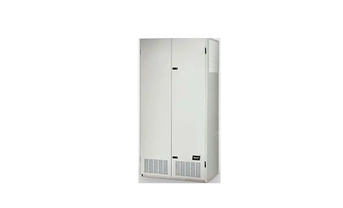
General Description
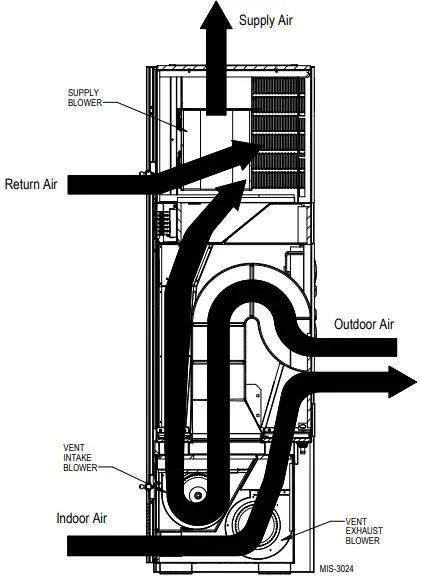
The I-TEC energy recovery ventilator (ERV) economizer ventilator system is designed to provide energy efficient, cost effective ventilation to meet IAQ (indoor air quality) requirements while still maintaining good indoor comfort and humidity control for a variety of applications such as schools, classrooms, lounges, conference rooms and others. It provides a constant supply of fresh air for control of airborne pollutants including CO2, smoke, radon, formaldehyde, excess moisture, virus and bacteria.
The ERV incorporates rotary heat exchanger technology to remove both heat and moisture. The package consists of unique rotary energy recovery cassettes that can be easily removed for cleaning or maintenance.
It has two 15″ diameter heat transfer wheels for efficient heat transfer. The heat transfer wheels use a permanently bonded dry dessicant coating for total heat recovery.
The I-TEC ERV is also provided with filters to reduce the required service needed and to extend the life of the heat recovery wheels. The exhaust air blower is protected by disposable filters, and the intake air blower is protected by washable filters. Both are accessible without the need for tools
Ventilation is accomplished with two blower/motor assemblies for maximum ventilation at low sound levels. The intake and exhaust blowers can be independently adjusted to maintain desired building pressurization conditions. The rotating wheels provide the heat transfer effectively during both summer and winter conditions. Provides required ventilation to meet the requirements of ASHRAE 62.1 Standard.
NOTE: During operation below 5°F outdoor temperature, freezing of moisture in the heat transfer wheel can occur. Consult the factory if this possibility exists.
When the outdoor air is cool, the unit provides economizer operation by stopping the ERV wheels and allowing the cool air into the room when needed.
The ERV economizer is designed to economize in cooling mode when the outdoor temperature is below the outdoor temperature sensor setpoint. This is factory set at 60º F. Above 60º, economizer operation is inhibited. Economizer operation is also inhibited when in heating mode.
Economizer operation consists of disabling the ERV cassette wheels from operating thus bringing in fresh air to the room and exhausting stale air. Since the ERV wheels are not turning, room heat is not recovered and is exhausted from the room. Bard Part #8403-060
programmable electronic thermostat must be used with this vent package because three stages of cooling are required.
Control Wiring
The I-TEC ERV comes wired from the factory ready to operate in manual mode (ON/OFF cycling) and set to 375 CFM of ventilation. Care must be taken when
deciding how to control the operation of the ventilator.
When designing the control circuit for the ventilator, the following requirements must be met.
- The indoor blower must be run whenever the I-TEC ERV is run.
- Select and configure the correct CFM ventilation level that the I-TEC ERV needs to operate and configure the system to this level following later instructions within this section. Over ventilating serves no useful purpose and significantly affects the overall efficiency of the heat pump system. System operating costs would also increase.
- Run the I-TEC ERV only during periods when the conditioned space is occupied. Running the ERV during unoccupied periods wastes energy, decreases the expected life of the ERV and can result in large moisture buildup in the structure. The ERV removes 60-70% of the moisture in the incoming air, not 100% of it. Running the ERV when the structure is unoccupied allows moisture to build up in the structure because there is little or no cooling load. Thus, the air conditioner is not running enough to remove the excess moisture being brought in. Use a control system that in some way can control the system based upon occupancy.
Notice
Operating the I-TEC ERV during unoccupied periods can result in a build up of excess moisture in the structure.
Recommended Control Sequence
Use a programmable electronic thermostat with auxiliary terminal to control the ERV based on daily programmed occupancy periods. Bard markets and recommends Bard Part #8403-060 programmable electronic thermostat.
NOTE: The thermostat must have three stages of cooling.
NOTE: The ventilation package comes with a blower interlock function, but is disabled when it is shipped from the factory in case a thermostat with an occupancy output or occupancy sensor is not utilized and “A” terminal to “G” terminal must be tied to drive the ventilation package. If a thermostat or control does drive occupancy output, remove the tape from the orange wire located in the low voltage terminal box, and connect it to the “G” terminal to activate this function.
Changing Ventilation CFM Rates in Manual Mode
WARNING
- ELECTRICAL SHOCK HAZARD.
- DISCONNECT THE REMOTE ELECTRIC POWER SUPPLIES BEFORE SERVICING
- ELECTRICAL SHOCK CAN RESULT IN SERIOUS INJURY OR DEATH
To adjust the airflow ventilation rate, first refer to Table 1 to look up the Flow Index needed for the intake and exhaust blowers for the CFM required. Then, perform the following steps:
- Open front swinging doors of main unit (by popping front door latches).
- Throw main power disconnect to the OFF position to eliminate risk of injury or death due to electrical shock.
- Remove five (5) screws holding front ERV door in place (see Figure 1 on page 6).
- Remove ERV control panel cover by removing four (4) screws.
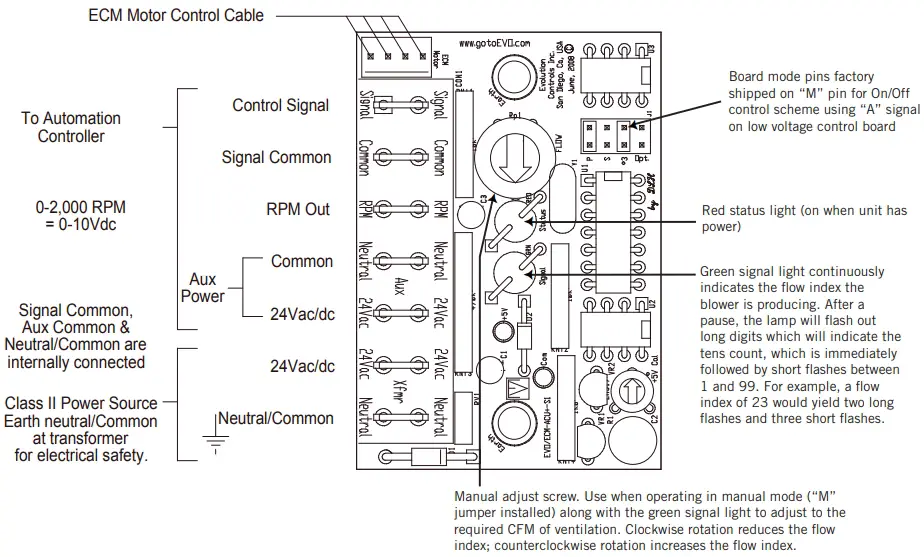
- Locate two 0-10Vdc motor control boards in control panel (see Figure 2 on page 7).
- On intake motor control board, observing green status light, turn manual adjust potentiometer counterclockwise to increase flow index or clockwise to reduce flow index to match desired setting.
NOTE: After long pause, the green status light will blink long-blinks for the ten count of the flow rate index, then immediately followed by fast blinks which indicate the second digit. For example, a flow index of 23 would be two long blinks, followed by three fast blinks of the green status light. - On exhaust motor control board, observing green status light, turn manual adjust potentiometer counterclockwise to increase flow index or clockwise to reduce flow index to match desired setting.
NOTE: Same green status light blink as Step #6.
TABLE 1
ERV “Manual Mode” Jumper Pin on “M” Terminal
| CFM | Flow Index (Light Blink Code) |
| 450 | 100 |
| 425 | 89 |
| 400 | 83 |
| 375 | 76 |
| 350 | 59 |
| 325 | 50 |
| 300 | 40 |
| 275 | 32 |
| 250 | 25 |
| 225 | 12 |
| 200 | 9 |
| 175 | 4 |
| 150 | 1 |
To adjust the airflow ventilation rate (NO CO2 CONTROL/NONMODULATING), determine the flow index needed for the intake and exhaust blowers for the required CFM. Use a small phillips-head screwdriver to make adjustments.
- Locate two (2) 0-10Vdc motor control boards in control panel.
- On intake motor control board (RH side of control panel), observing green status light, turn manual adjust potentiometer counterclockwise to increase flow index or clockwise to reduce flow index to match desired setting. (NOTE: After long pause, the green status light will blink long blinks for the ten count of the flow rate index, which then is immediately followed by fast blinks which indicate the second digit. For example, a flow index of 23 would be two long blinks, followed by 3 fast blinks of the green status light.)
- On exhaust motor control board (LH side of control panel), observing green status light, turn manual adjust potentio meter counterclockwise to increase flow index or clockwise to reduce flow index to match desired setting. (See NOTE in Step 2.)
FIGURE 1 ERV Control Acces
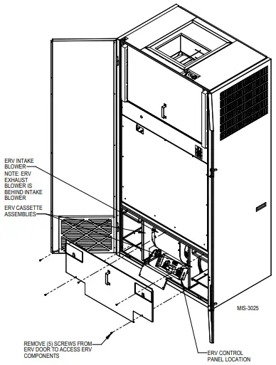
FIGURE 2 Control Board Configuration/Setting
Energy Recovery Ventilator Maintenance
General Information
The ability to clean exposed surfaces within air moving systems is an important design consideration for the maintenance of system performance and air quality.
The need for periodic cleaning will be a function of operating schedule, climate and contaminants in the indoor air being exhausted and in the outdoor air being supplied to the building. All components exposed to the airstream, including energy recovery wheels, may require cleaning in most applications.
Rotary counter flow heat exchanges (heat wheels) with laminar airflow are “self cleaning” with respect to dry particles. Smaller particles pass through; larger particles land on the surface and are blown clear as the flow direction is reversed. For this reason, the primary need for cleaning is to remove films of oil-based aerosols that have condensed on energy transfer surfaces. Buildup of material over time may eventually reduce airflow. Most importantly, in the case of desiccant-coated (enthalpy) wheels, such films can close off micron-sized pores at the surface of the desiccant material, reducing the efficiency with which the desiccant can absorb and desorb moisture.
Frequency
In a reasonably clean indoor environment such as a school, office building or home, experience shows that reductions of airflow or loss of sensible (temperature) effectiveness may not occur for 10 or more years.
However, experience also shows that measurable changes in latent energy (water vapor) transfer can occur in shorter periods of time in commercial, institutional and residential applications experiencing moderate occupant smoking or with cooking facilities.
In applications experiencing unusually high levels of occupant smoking, such as smoking lounges, nightclubs, bars and restaurants, washing of energy transfer surfaces, as frequently as every 6 months, may be necessary to maintain latent transfer efficiency.
Similar washing cycles may also be appropriate for industrial applications involving the ventilation of high levels of smoke or oil-based aerosols such as those found in welding or machining operations, for example. In these applications, latent efficiency losses of as much as 40% or more may develop over a period of 1-3 years.
Cleanability and Performance
In order to maintain energy recovery ventilation systems, energy transfer surfaces must be accessible for washing to remove oils, grease, tars and dirt that can impede performance or generate odors. Washing of the desiccant surfaces is required to remove contaminate buildups that can reduce adsorption of water molecules. The continued ability of an enthalpy.
wheel to transfer latent energy depends upon the permanence of the bond between the desiccant and the energy transfer surfaces.
Bard wheels feature silica gel desiccant permanently bonded to the heat exchange surface without adhesives; the desiccant will not be lost in the washing process. Proper cleaning of the Bard energy recovery wheel will restore latent effectiveness to near original performance.
Maintenance Procedures
NOTE: Local conditions can vary and affect the required time between routine maintenance procedures, therefore all sites (or specific units at a site) may not have the same schedule to maintain acceptable performance. The following timetables are recommended and can be altered based on local experience.
Quarterly Maintenance
- Inspect mist eliminator/prefilter and clean if necessary. This filter is located in the fresh air intake hood on the front of the unit. This is an aluminum mesh filter and can be cleaned with water and any detergent not harmful to aluminum.
- Inspect wall-mount unit filter and clean or replace as necessary. This filter is located either in the unit, in a return air filter grille assembly, or both.
If in the unit it can be accessed by removing the lower service door on the front of the unit. If in a return air filter grille, by hinging the grille open to gain access. - Inspect energy recovery ventilator for proper wheel rotation and dirt buildup. This can be done in conjunction with Step 2 above. Energize the energy recovery ventilator after inspecting the filter and observe for proper rotation and/or dirt buildup.
- Recommended energy recovery wheel cleaning procedures follow Steps 5 through 8.
- Disconnect all power to unit. Remove the lower service door of the wall-mount unit to gain access to the energy recovery ventilator.
- Remove the front access panel on the ventilator.
Unplug amp connectors to cassette motors. Slide energy recovery cassette out of ventilator. - Use a shop vacuum with brush attachment to clean both sides of the energy recovery wheels.
- Reverse shop vacuum to use as a blower and blow out any residual dry debris from the wheel.
NOTE: Discoloration and staining of the wheel does not affect its performance. Only excessive buildup of foreign material needs to be removed. - If any belt chirping or squealing noise is present, apply a small amount of LPS-1 or equivalent dry film lubricant to the belt.
Annual Maintenance
- Inspect and conduct the same procedures as outlined under Quarterly Maintenance.
- To maintain peak latent (moisture) removal capacity, it is recommended that the energy recovery wheels be sprayed with a diluted non acid based evaporator coil cleaner or alkaline detergent solution such as 409.
NOTE: Do not use acid-based cleaners, aromatic solvents, temperatures in excess of 170° F or steam. Damage to the wheel may result.
Do not disassemble and immerse the entire heat wheel in a soaking solution, as bearing and other damage may result. - Rinse wheel thoroughly after application of the cleaning solution, and allow to drain before reinstalling.
- No re-lubrication is required to heat wheel bearings of the drive motor, or to the intake and exhaust blower motors.
- If any belt chirping or squealing noise is present, apply a small amount of LPS-1 or equivalent dry film lubricant to the belt.
FIGURE 3 Hub Assembly with Ball Bearings
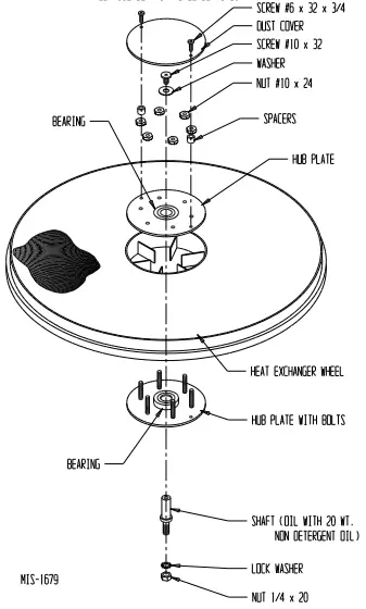
FIGURE 4 Ventilation Airflow Diagram