Bard Air Conditioner User Manual

General Notes
- Revised and/or additional pages may be issued from time to time.
- A complete and current manual consists of pages shown in the contents section.
Important
- Contact the installing and/or local Bard distributor for all parts requirements. Make sure to have the complete model and serial number available from the unit rating plates.
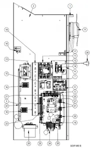
CABINET COMPONENTS
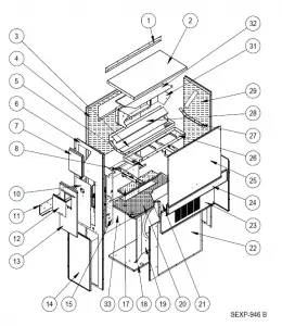
CABINET COMPONENTS
| Dwg No. | Part Number | Description | W3 | W3 | W3 | W3 | W3 | W3 |
| 1 1 1 | 113-149-* ① 113-360 ② 113-149-4 ③ | Top Rain Flashing Top Rain Flashing Top Rain Flashing | X X X | X X X | X X X | X X X | X X X | X X X |
| 2 2 2 | S507-308-* ① S507-319 ② S507-320 ③ | Top Top Top | X X X | X X X | X X X | X X X | X X X | X X X |
| 3 3 | S123-130 S123-143 ②③ | Drain Pan Drain Pan | X X | X X | X X | X X | X X | X X |
| 4 4 4 | S509-451 S509-455 ② S509-453 ③ | Upper Back Upper Back Upper Back | X X X | X X X | X X X | X X X | X X X | X X X |
| 5 | 105-1302 | Grommet Retainer | X | X | X | X | X | X |
| 6 6 6 | S501-935-* ① S501-998 ② S501-943 ③ | Right Side Right Side Right Side | X X X | X X X | X X X | X X X | X X X | X X X |
| 7 7 7 | S543-175-* ① S543-185 ② S543-184 ③ | Right Side Cover Plate (Outer) Right Side Cover Plate (Outer) Right Side Cover Plate (Outer) | X X X | X X X | X X X | X X X | X X X | X X X |
| 8 | 113Y480 | Filter Bracket | 2 | 2 | 2 | 2 | 2 | 2 |
| 9 | 137-259 | Fill Plate | X | X | X | X | X | X |
| 10 10 | S132-104 S132-172 | Control Panel Cover (Inner) Control Panel Cover (Inner) | X | X | X | X | X | X |
| 11 | 113-140 | Bottom Mounting Bracket | X | X | X | X | X | X |
| 12 12 12 | S153-218 ① S153-405 ② S153-387 ③ | Disconnect Access Door Disconnect Access Door Disconnect Access Door | X X X | X X X | X X X | X X X | X X X | X X X |
| 13 13 13 | S533-228 ① S533-235 ② S533-236 ③ | Control Panel Cover (Outer) Control Panel Cover (Outer) Control Panel Cover (Outer) | X X X | X X X | X X X | X X X | X X X | X X X |
| 14 14 14 | 118-124-* ① 118-140 ② 118-139 ③ | Side Grille Side Grille Side Grille | 2 2 2 | 2 2 2 | 2 2 2 | 2 2 2 | 2 2 2 | 2 2 2 |
| 15 | Control Panel Assembly | See Control Panel Assy. Drawing & Parts List Assy. | X | X | X | X | X | X |
| 17 17 | S536-498 S536-877 ② | Cond. Partition Block Off Plate Cond. Partition Block Off Plate | X X | X X | X X | X X | X X | X X |
| 18 18 | S127-472 S127-533 ② | Lower Base Lower Base | X X | X X | X X | X X | X X | X X |
| 19 19 | 125-081 125-083 ② | Fan Shroud Fan Shroud | X X | X X | X X | X X | X X | X X |
| 20 20 | S521Y527 S521*-561 ② | Condenser Partition Condenser Partition | X X | X X | X X | X X | X X | X X |
| 22 22 22 | 118-104-* ① 118-109 ② 118-114 ③ | Condenser Grille Condenser Grille Condenser Grille | X X X | X X X | X X X | X X X | X X X | X X X |
| 23 23 23 | S553-523-* ① S553-549 ② S553-550 ③ | Vent Option Door Vent Option Door Vent Option Door | X X X | X X X | X X X | X X X | X X X | X X X |
| 24 24 24 | S553-524-* ① S553-553 ② S553-554 ③ | Filter Door Filter Door Filter Door | X X X | X X X | X X X | X X X | X X X | X X X |
| 25 25 25 | S514-241-* ① S514-238 ② S514-239 ③ | Upper Front Upper Front Upper Front | X X X | X X X | X X X | X X X | X X X | X X X |
| 26 | 121Y467 | Blower Partition | X | X | X | X | X | X |
| 27 | 105Y850 | Side Support | X | X | X | X | X | X |
| 28 | 137-685 | Bottom Evaporator Fill | X | X | X | X | X | X |
| 29 29 29 | S501-936-* ① S501-999 ② S501-946 ③ | Left Side Left Side Left Side | X X X | X X X | X X X | X X X | X X X | X X X |
| 30 | 147-044 | Evaporator Support | X | X | X | X | X | X |
| 31 | S111Y030 | Outlet Air Frame Assembly | X | X | X | X | X | X |
| 32 | 135Y123 | Heat Shield | X | X | X | X | X | X |
| 33 33 33 | 109-450 109-454 ② 109-452 ③ | Lower Back Lower Back Lower Back | X X X | X X X | X X X | X X X | X X X | X X X |
| NS | 135-329 | Air Baffle | X | X | X | X | X | X |
| NS | BOP-3 | Blank Off Plate | X | X | X | X | X | X |
| NS | 5252-033 | Bard Nameplate | X | X | X | X | X | X |
- Exterior cabinet parts are manufactured with various paint color options. To ensure the proper paint color is received, include the complete model and serial number of the unit for which cabinet parts are being ordered. k Exterior cabinet parts are manufactured from stainless steel Code “S”
- Exterior cabinet parts are manufactured from aluminum Code “A”
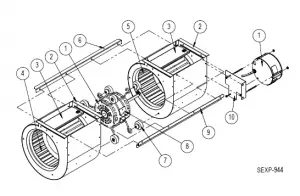
FUNCTIONAL COMPONENTS
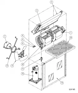
FUNCTIONAL COMPONENTS
| Dwg No. | Part Number | Description | W3 | W3 | W3 | W3 | W3 | W3 | W3 | W3 |
| 1 1 1 1 | S900-364-001 S900-365-001 900-364-002 900-365-002 | Blower Assembly Blower Assembly Blower Assembly Blower Assembly | X | X | X | X |
X |
X |
X |
X |
| 2 2 2 2 | 917-0355 917-0356 917-0357 917-0358 | Evaporator Coil w/Distributor Assy. Evaporator Coil – Coated w/Distributor Assy. Evaporator Coil w/Distributor Assy. Evaporator Coil – Coated w/Distributor Assy. | X X | X X | X X | X X |
X X |
X X |
X X |
X X |
| 3 3 | 800-0456 800-0479 | Distributor Assembly Distributor Assembly | X | X | X | X | X | X | X | X |
| 4 | 1171-023 | 1/4″ Receptacle | X | X | X | X | X | X | X | X |
| 5 | 1171-024 | 1/4″ Turn Retainer | X | X | X | X | X | X | X | X |
| 6 | 1171-022 | 1/4″ Turn Fastener | X | X | X | X | X | X | X | X |
| 7 7 | 8103-029 8103-030 | Condenser Motor Condenser Motor | X | X | X | X | X | X | X | X |
| 8 8 | 8200-001 8200-050 ① | Fan Motor Mount Stainless Steel Fan Motor Mount | X X | X X | X X | X X | X X | X X | X X | X X |
| 9 9 | S5151-045 S5151C045 ① | Fan Blade Coated Fan Blade | X X | X X | X X | X X | X X | X X | X X | X X |
| 10 | CMA-31 | Dirty Filter Switch Kit | X | X | X | X | X | X | X | X |
| 11 | CMA-39 | Low Ambient Control (Screw On) ② | X | X | X | X | X | X | X | X |
| 12 12 12 12 12 12 | 8000-277 8000-365 8000-366 8000-278 8000-283 8000-342 | Compressor Compressor Compressor Compressor Compressor Compressor | X | X |
X |
X |
X |
X |
X |
X |
| 13 13 13 13 | 5051-203BX 5054-203BX 5051-202BX 5054-202BX | Condenser Coil Condenser Coil – Coated Condenser Coil Condenser Coil – Coated | X X | X X | X X | X X |
X X |
X X |
X X |
X X |
| 14 14 14 14 14 | 7004-019 7003-031 7004-026 7004-048 7004-062 | Air Filter 1″ Throw-Away (16x30x1) Air Filter 1″ Washable ② (16x30x1) Air Filter 2″ Pleated ② (16x30x2) Air Filter 2″ Pleated – MERV 11 ② (16x30x2) Air Filter 2″ Pleated – MERV 13 ② (16x30x2) | X X X X X | X X X X X | X X X X X | X X X X X | X X X X X | X X X X X | X X X X X | X X X X X |
| NS | 8406-142 | High Pressure Switch (Screw On) | X | X | X | X | X | X | X | X |
| NS | 8406-140 | Low Pressure Switch (Screw On) | X | X | X | X | X | X | X | X |
| NS | 5201-021 | Filter Drier | X | X | X | X | X | X | X | X |
| NS | 5451-024 | Tubing Isolation Grommet | X | X | X | X | X | X | X | X |
| NS | 6031-009 | Coremax Valve Core | X | X | X | X | X | X | X | X |
| NS | 1171-070 | Filter Door Clip | X | X | X | X | X | X | X | X |
| NS | 1171-068 | Filter Door Screw | X | X | X | X | X | X | X | X |
| NS | 1171-069 | Filter Door Screw Retainer | X | X | X | X | X | X | X | X |
NS – Not Shown
- Used with stainless steel cabinet option
- Optional on these models
CONTROL PANEL
CONTROL PANEL
| Dwg No. | Part Number | Description | W3 | W3 | W3 | W3 | W3 | W3 | W3 | W3 |
| 1 | 117Y137 | Control Panel Top | X | X | X | X | X | X | X | X |
| 2 | 117Y395 | Control Panel | X | X | X | X | X | X | X | X |
| 3 | 135-122 | Wire Shield | X | X | X | X | X | X | X | X |
| 4 | 8201-130 | Blower Relay | X | X | X | X | X | X | X | X |
| 5 | 3020-004 | Communications Sheathed Cable | X | X | X | X | X | X | X | X |
| 6 | 8201-126 | 3 Phase Line Monitor 50/60 Hz | X | X | X | X | X | X | ||
| 7 | 8201-130 | Alarm Relay | X | X | X | X | X | X | X | X |
| 8 | 8201-164 | Compressor Control Module | X | X | X | X | X | X | X | X |
| 9 | 8301-057 | Filter Switch w/Adjustment | X | X | X | X | X | X | X | X |
| 10 | 8301-068-001* | UPC3-MULTI-TEC 2.0.0 | X | X | X | X | X | X | X | X |
| 11 11 | 8401-035 8401-038 | Contactor 3-Pole 25 Amp Contactor 2-Pole 40 Amp | X | X | X | X | X | X | X | X |
| 12 | 8401-039 | Aux. NC Contact | X | X | X | X | X | X | ||
| 13 13 | 8407-048 8407-050 | Transformer 208/240-24 75VA Transformer 480/24VAC 75VA | X | X | X | X | X | X | X | X |
| 14 | 8607-013 | Terminal Block 2 Term. 240V | X | X | ||||||
| 15 | 8607-017 | Terminal Block 240V 2 Terminal | X | X | X | X | X | X | X | X |
| 16 | 8607-037 | Terminal Block 4 Position | X | X | X | X | X | X | X | X |
| 17 | 8607-041 | Park Terminal | X | X | X | X | X | X | X | X |
| 18 | 8611-006 | Ground Terminal | X | X | X | X | X | X | X | X |
| 19 | 8611-140-1200 | 2-1/4″ x 1″ Cable Duct x 12″ | X | X | X | X | X | X | X | X |
| 20 | 8611-147 | 3-Pin Circuit Board Connector | X | X | X | X | X | X | X | X |
| 21 | 8611-148 | 4-Pin Circuit Board Connector | X | X | X | X | X | X | X | X |
| 22 | 8611-149 | 9-Pin Circuit Board Connector | X | X | X | X | X | X | X | X |
| 23 | 8611-185 | 8-Pin Circuit Board Connector | X | X | X | X | X | X | X | X |
| 24 | 8611-189 | 35MM DIN Rail 9″ | X | X | X | X | X | X | X | X |
| 25 | 8611-192 | Small 3-Pin Circuit Board Connector | X | X | X | X | X | X | X | X |
| 26 | 910-1935 | Evap. Temp. Sensor Assembly | X | X | X | X | X | X | X | X |
| 27 | 8611-183 | 2-Pin Circuit Board Connector | X | X | X | X | X | X | X | X |
| 28 | 8611-150 | DIN Rail Terminal Block | X | X | X | X | X | X | X | X |
| 29 29 | 8552-052 8552-002 | Compressor Capacitor Outdoor Motor Capacitor | X | X | X | X | X | X | X | X |
| NS NS | 3000-1224 3000-1231 | Compressor Plug/Harness Compressor Plug/Harness | X | X | X | X | X | X | X | X |
| NS NS NS NS | 8615-038 8615-054 8615-052 8615-067 | Circuit Breaker 35A 2 Pole (Opt.) Circuit Breaker 20A 3 Pole (Opt.) Circuit Breaker 30A 3 Pole (Opt.) Toggle Disconnect (Opt.) | X | X |
X |
X | X | X |
X |
X |
| NS NS NS NS | 4207-108 4207-207 4207-307 4207-602 | Wiring Diagram Wiring Diagram Wiring Diagram Wiring Diagram | X | X | X |
X | X | X | X |
X |
| NS | 8301-075 | USB Micro Cable Female to Male | X | X | X | X | X | X | X | X |
- Replacement part will have a letter attached to the end of the part number to designate software version Example: 8301-068-001A). A software upgrade of all PLCs onsite (units and controllers) should accompany any
PLC replacement. Latest revisions of software, change log and instructions are available on the Bard website at http://www.bardhvac.com/software-download/ - Circuit breakers listed are for units without electric heat, “0Z” models. Hot gas bypass models not available without electric heat. See heater replacement parts manual for units with electric heat.
NS = Not Shown
BLOWER ASSEMBLY
| Dwg No. | Part Number | Description | S90 | S90 | S90 | S90 |
| 1 | S8106-068-0150 | Programmed Blower Motor & Control (230/208V) | X
O | X
O |
X
O |
X
O |
| 1 | S8106-068-0152 | Programmed Blower Motor & Control (230/208V) | ||||
| 1 | S8106-069-0151 | Programmed Blower Motor & Control (460V) | ||||
| 1 | S8106-069-0153 | Programmed Blower Motor & Control (460V) | ||||
| 1 | C8106-068-0150 | Programmed Control Only (230/208V) | ||||
| 1 | C8106-068-0152 | Programmed Control Only (230/208V) | ||||
| 1 | C8106-069-0151 | Programmed Control Only (460V) | ||||
| 1 | C8106-069-0153 | Programmed Control Only (460V) | ||||
| 2 | 151-111 | Housing | 2 | 2 | 2 | 2 |
| 3 | 144-174 | Diffuser | 2 | 2 | 2 | 2 |
| 4 | 5152-090 | Wheel CW | X | X | X | X |
| 5 | 5152-091 | Wheel CCW | X | X | X | X |
| 6 | 105-870 | Back Brace | X | X | X | X |
| 7 | 5451-011 | Grommets | 6 | 6 | 6 | 6 |
| 8 | 8200-031 | Motor Mount | X | X | X | X |
| 9 | 103-401 | Front Brace | X | X | X | X |
| 10 | 113-761 | Motor Control Bracket | X | X | X | X |
FREECOOLING COMPONENTS
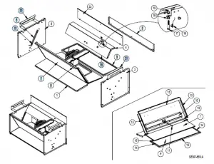
| Dwg. No. | Part Number | Description |
| 1 | 137-738 | Lower Front Partition |
| 2 | 137-745 | Lower Rear Fill |
| 3 | S101-979 | Right Side |
| 4 | S137-865 | Upper Rear Partition |
| 5 | S101-978 | Left Side |
| 6 | S105-1344 | Blade Seal Angle |
| 7 | S139-324 | Blade |
| 8 | S137-867 | Upper Front Partition |
| 9 | S137-740 | Lower Rear Partition |
| 10 | 141-430 | Blade Support |
| 11 | 8602-044 | 1/4 x 9″ Rod |
| 12 | S1921-067-0800 | 29-9/16″ Damper Blade Seal |
| 13 | S1921-067-1004 | 13″ Damper Blade Seal |
| 14 | S1921-067-0802 | 10-11/16″ Damper Blade Seal |
| 15 | S1921-067-2504 | 29-3/8″ Damper Blade Seal |
| 16 | 8408-044 | Sensor 10K Ohm Curve J w/ 5/16″ Clip |
| 17 | 1012-052 | Hex Head Bolt 5/16 – 18×1-3/4″ 0.0005 Zinc w/ Yellow Chromate |
| 18 | 1012-210 | 5/16″ Nut 0.0005 Zinc w/ Yellow Chromate |
| 19 | 113-541 | Sensor Bracket |
| 20 | 113-542 | Filter Bracket |
| 21 | 113-543 | Filter Bracket |
| 22 | 137-746 | Upper Rear Fill |
| 23 | 8602-040 | Rod Bracket |
| NS | 537-751 | Condenser Cover Plate Assembly |
FREECOOLING AIR HOOD
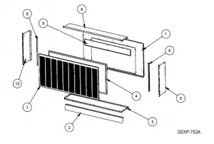
| Dwg. No. | Part Number | Description |
| 1 | 115-284-* ① | Hooded Front Door |
| 1 | 115-291 ② | Hooded Front Door |
| 1 | 115-290 ③ | Hooded Front Door |
| 2 | 113-538-* ① | Bottom Divider Bracket |
| 2 | 113-568 ② | Bottom Divider Bracket |
| 2 | 113-571 ③ | Bottom Divider Bracket |
| 3 | S127-495-* ① | Hood Bottom |
| 4 | 7003-079 | Mist Filter 36-1/4″ x 15-7/8″ x 7/8″ |
| 5 | S101-984-* ① | Right Side |
| 5 | S101-1033 ② | Right Side |
| 5 | S101-1013 ③ | Right Side |
| 6 | 105-1346 | Side Filter Angle |
| 6 | 105-1346 ② | Side Filter Angle |
| 6 | 105-1370 ③ | Side Filter Angle |
| 7 | 553-660-* ① | Hood Mounting Door |
| 7 | 553-712 ② | Hood Mounting Door |
| 7 | 553-703 ③ | Hood Mounting Door |
| 8 | S107-346-* ① | Hood Top |
| 8 | S107-354 ② | Hood Top |
| 8 | S107-353 ③ | Hood Top |
| 9 | 553-613 | Filter Door |
| 9 | 553-632 ② | Filter Door |
| 9 | 553-636 ③ | Filter Door |
| 10 | S101-873-* ① | Left Side |
| 10 | S101-997 ② | Left Side |
| 10 | S101-882 ③ | Left Side |
| 920-0375 | Complete Hood Assembly – Beige | |
| 920-0376 | Complete Hood Assembly – White | |
| 920-0377 | Complete Hood Assembly – Buckeye Gray | |
| 920-0422 | Complete Hood Assembly – Stainless Steel | |
| 920-0411 | Complete Hood Assembly – Aluminum |
- Exterior cabinet parts are manufactured with various paint color options. To ensure the proper paint color is received, reference the following codes: Beige -X Buckeye Gray -4 White -1 k Exterior cabinet parts are manufactured from stainless steel Code “S”
- Exterior cabinet parts are manufactured from aluminum Code “A”
FREECOOLING DAMPER MOTOR
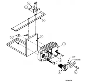
| Dwg. No. | Part Number | Description |
| 1 | 141-466 | Actuator Support Plate |
| 3 | 8602-067 | Direct Coupled Actuator |
| 4 | 8602-008 | Ball Joint |
| 5 | 8602-068 | Belimo Actuator Crank Arm 1/2″ |
| 6 | 1012-174 | 1/4″ – 20×3 – 1/4 Hex Cap Screws |
| 7 | 1012-201 | 1/4-20 Steel Keps Hex Nut Zinc |
| 8 | 141-464 | Actuator Support Bar |
| 9 | 113-655 | Blade Switch Bracket |
| 10 | 8406-150 | Lever Switch SPDT Sealed Pilot Duty |
| 11 | 1012-178 | 4-40 x 5/8″ Phillips Pan Head Machine Screw, Zinc Plated |
| 12 | 1012-231 | 4-40 Steel Keps Hex Nut Zinc |
| NS | 910-2014 | Outdoor Temperature Sensor |


