![]() QR120P Heat Recovery Ventilation Unit
QR120P Heat Recovery Ventilation Unit
Instruction Manual
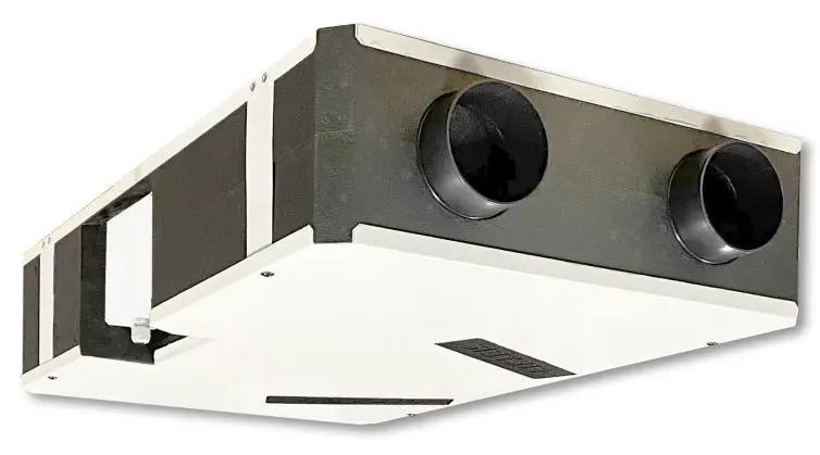
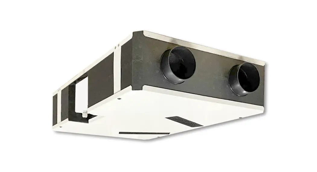
QR120P
Heat Recovery Ventilation Unit
Read this manual carefully before using the product and keep it in a safe place for reference as necessary.
This product was constructed up to standard and in compliance with regulations relating to electrical equipment and must be installed by technically qualified personnel.
The manufacturer assumes no responsibility for damage to persons or property resulting from failure to observe the instructions contained in this manual.
PRECAUTIONS
WARNING
Make sure that the mains supply to the unit is disconnected before performing any installation, service, maintenance, or electrical work!
WARNING
The installation and service of the unit and complete ventilation system must be performed by an authorized installer and in accordance with local rules and regulations.
WARNING
If any abnormality in operation is detected, disconnect the device from the main supply and contact a qualified technician immediately.
Transport and storage
- Do not leave the device exposed to atmospheric agents (rain, sun, snow, etc.).
- Duct connections/duct ends must be covered during storage and installation.
Installation
- After removing the product from its packaging, verify its conditions. Do not leave packaging within the reach of children or people with disabilities.
- Beware of sharp edges. Use protective gloves.
- The device should not be used as an activator for water heaters, stoves, etc., nor should it discharge into hot air/fume vent ducts deriving from any type of combustion unit or tumble dryer. It must expel air outside via its own special duct.
- If the environment in which the product is installed also houses a fuel-operating device (water heater, methane stove etc., that is not a “sealed chamber” type), it is essential to ensure adequate air intake, to ensure good combustion and proper equipment operation.
- The electrical system to which the device is connected must comply with local regulations.
- Before connecting the product to the power supply or the power outlet, ensure that:
– the data plate (voltage and frequency) correspond to those of the electrical mains
– the electrical power supply/socket is adequate for maximum device power. - For installation an omnipolar switch should be incorporated in the fixed wiring, in accordance with the wiring rules, to provide a full disconnection under overvoltage category III conditions (contact opening distance equal to or greater than 3mm).
Use
- The device should not be used for applications other than those specified in this manual.
- This appliance can be used by children aged 8 years and above and persons with reduced physical, sensory or mental capabilities or lack of experience and knowledge if they have been given supervision or instruction concerning the use of the appliance in a safe way and understand the hazards involved. Children shall not play with the appliance. Cleaning and user maintenance shall not be made by children without supervision.
- Do not touch the appliance with wet or damp hands/feet.
- The device is designed to extract clean air only, i.e. without grease, soot, chemical or corrosive agents, or flammable or explosive mixtures.
- Do not use the product in the presence of inflammable vapors, such as alcohol, insecticides, gasoline, etc.
- The system should operate continuously, and only be stopped for maintenance/service.
- Do not obstruct ducts or grilles to ensure optimum air passage.
- Do not immerse the device or its parts in water or other liquids.
- Operating temperature: 0°C up to +40°C.
Service
- Although the mains supply to the unit has been disconnected there is still a risk of injury due to rotating parts that have not come
to a complete standstill. - Beware of sharp edges. Use protective gloves.
- Use original spare parts only for repairs.
PRODUCT INFORMATION
3.1 General
This is the Installation, Use, and Maintenance Manual of the heat recovery ventilation units, model QR120P.
This manual consists of basic information and recommendations concerning installation, commissioning, use, and service operations to ensure a proper fail-free operation of the unit.
The key to proper, safe, and smooth operation of the unit is to read this manual thoroughly, use the unit according to the given guidelines and follow all safety requirements.
The QR120P is supplied with the CTRL-V multi-function control panel. The package also contains 1 plug for water drainage.
3.2 Dimensions and Weight
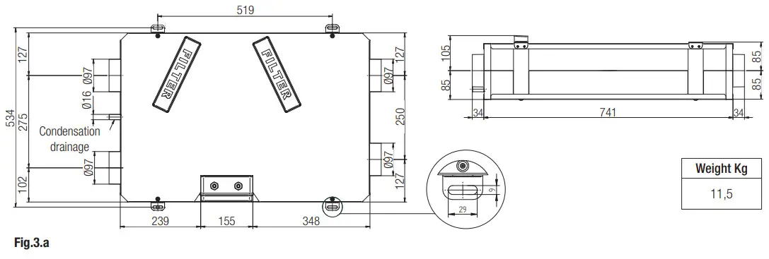
3.3 Duct connections
3.4 Space required
Make sure that enough space is left around the unit to allow easy maintenance (access to filters, terminal box, and inspection panel removal).
3.5 Rating label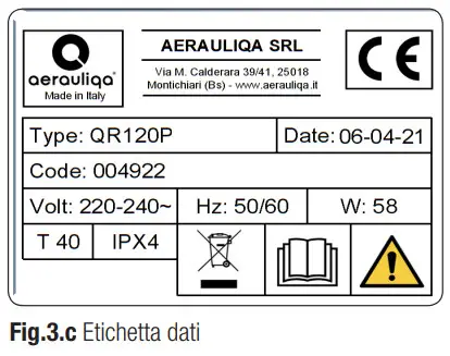
4 TRANSPORT AND STORAGE
WARNING
Make sure that specific warnings and cautions in Chapter 2 are carefully read, understood, and applied!
The appliance is delivered in one carton box.
The appliance should be stored and transported in such a way that it is protected against physical damage that can harm spigots, casing, display, etc…
It should be covered so that dust, rain, and snow cannot enter and damage the unit and its components.
INSTALLATION
WARNING
Make sure that specific warnings and cautions in Chapter 2 are carefully read, understood, and applied!
This section describes how to install the unit correctly.
The unit must be installed according to these instructions.
5.1 Unpacking
Verify that the unit (and eventual accessories) delivered is according to order before starting the installation. Any discrepancies from the ordered equipment must be reported to the supplier.
5.2 Where/how to install
- All OR units are meant for indoor installation in a heated space.
- Mount the unit on flat surface.
- Place the unit preferably in a separate room (e.g. storage, laundry room or similar).
- When choosing the location it should be kept in mind that the unit requires maintenance regularly and that the inspection door should be easily accessible.
- Leave free space for opening the removable panel and for removal of the main components (§3.4).
- The outdoor air intake of the building should if possible be put in the northern or eastern side of the building and away from other exhaust outlets like kitchen fan exhausts or laundry room outlets.
- The unit casing is provided with 1 condensation drainage.
5.3.1 Ceiling installation
The unit must be installed in the following position.
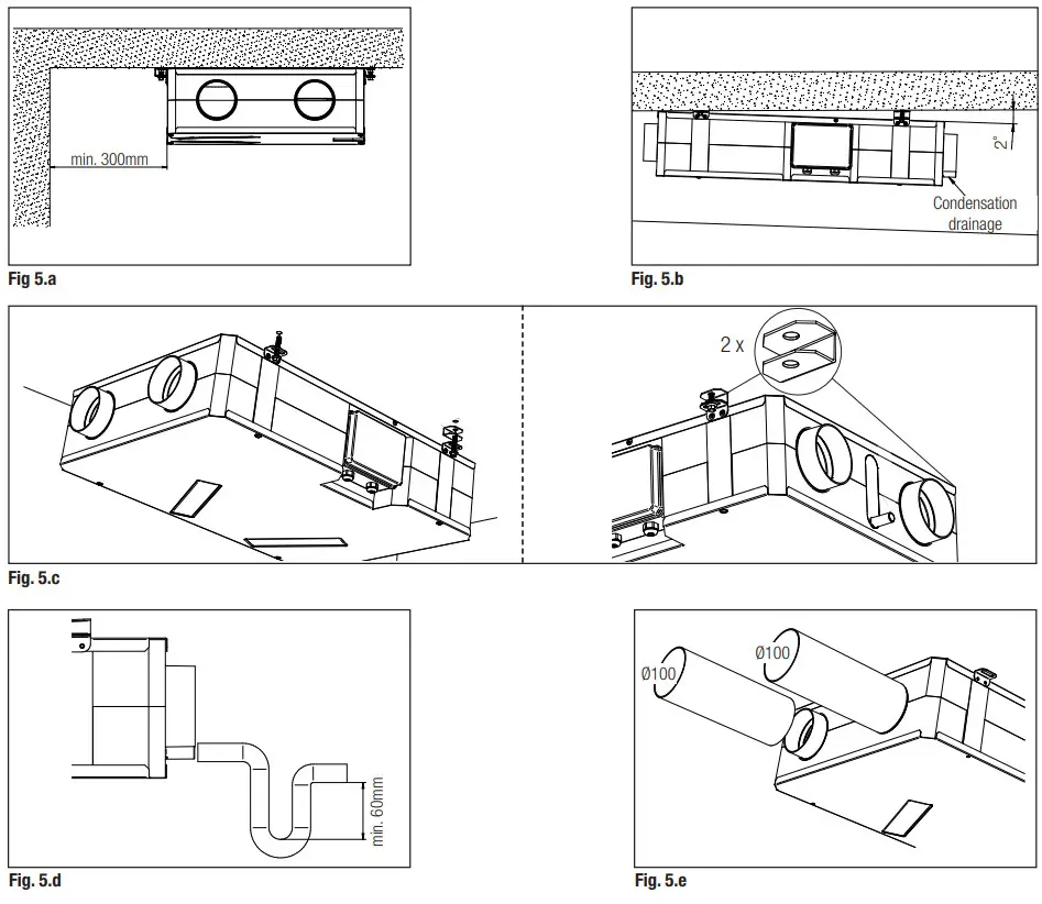
5. Prepare the surface where the unit is to be mounted. Make sure that the surface is flat, leveled and that it supports the weight of the unit. Perform the installation in accordance with local rules and regulations.
5. b.c It is important that the unit is tilted by 2° in order for the condensate drain to function properly: use the spacers supplied which must be mounted on the fixing brackets of the side with the condensate drain.
Use appropriate plugs and rods or screws (not supplied) to fix the unit to the ceiling. It is recommended to fit the unit with anti-vibration mounts (not supplied).
5.d Connect the drain connection to the drainage hole. Make sure of water and air tightness of all connections. It is recommended to use a U-bend (or similar) in the condensation drainage pipe.
5. e Connect the unit to the duct system. Make sure that all necessary accessories are used to create a functional ventilation solution. Connect the unit electrically according to §5.4. Check that it starts up correctly.
5.3.2 Wall installation
The unit must be installed in the following position: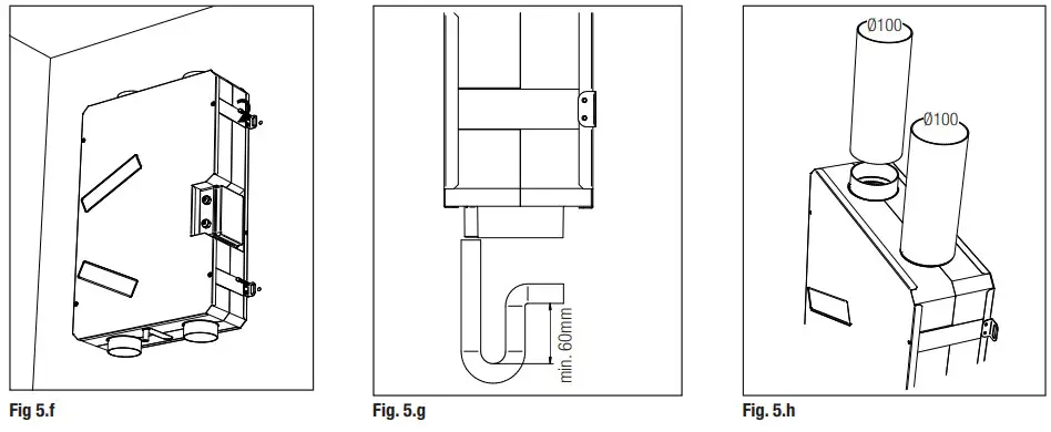
MANUTENZIONE ORDINARIA
5. f Prepare the surface where the unit is to be mounted. Make sure that the surface is flat, and leveled and that it supports the weight of the unit. Perform the installation in accordance with local rules and regulations.
Use appropriate plugs and rods or screws (not supplied) to fix the unit to the ceiling. It is recommended to fit the unit with anti-vibration mounts (not supplied).
5. g Connect the drain connection to the drainage hole. Make sure of water and air tightness of all connections. It is recommended to use a U-bend (or similar) in the condensation drainage pipe.
5. h Connect the unit to the duct system. Make sure that all necessary accessories are used to create a functional ventilation solution. Connect the unit electrically according to §5.4. Check that it starts up correctly.
5.4 Pre-cabled electric connections
WARNING
Make sure that the mains supply to the unit is disconnected before performing any installation, service, maintenance or electrical work!
WARNING
The installation and service of the unit and complete ventilation system must be performed by an authorized installer and in accordance with local rules and regulations.
The unit must be earthed.
The unit is wired internally from the factory.
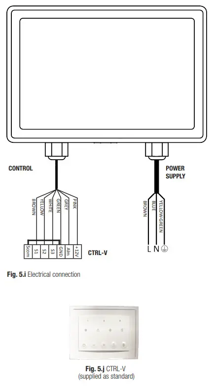
The unit comes pre-wired with:
- power supply cable (3-core: brown, blue, yellow/green).
- control cable, for connection to CTRL-V, supplied (6-core: brown, yellow, white, green, grey, pink).
Factory setting: speed 1 at 40%, speed 2 at 70%, and speed 3 at 100%.
5.5 Additional electric connections
WARNING
Make sure that the mains supply to the unit is disconnected before performing any installation, service, maintenance or electrical work!
WARNING
The installation and service of the unit and complete ventilation system must be performed by an authorized installer and in accordance with local rules and regulations.
The units must be earthed.
The unit is wired internally from the factory.
To connect the CTRL-V to the motherboard using a 6-core cable: 30m max length.
The figures below show the wiring diagram.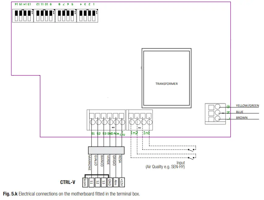
Inputs/commands
N°1 AC supply connector.
N°2 on/off inputs (volt-free contacts), for ambient sensors (named In1, In2).
N°1 6-pole connector for CTRL-V.
COMMISSIONING
6.1 Setting Fan speed
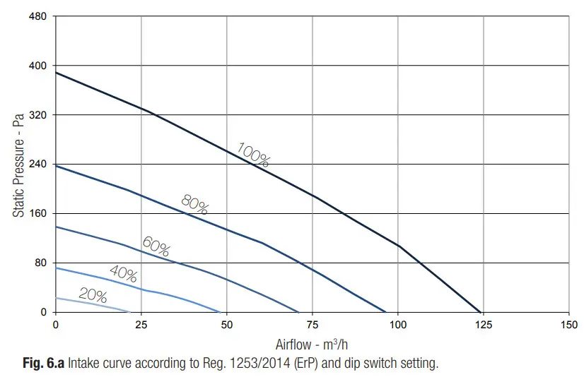
The speed of the unit can be adjusted during installation according to the required ventilation rate, by setting the relevant dip switch.
Figure 6. below shows the performance curve at different settings of the 0-10V signal to the motors. Consumption refers to the 2 motors.
Table 6. b indicates the efficiency of the heat exchanger and of the condensation produced in different climatic conditions, to help the installer or the designer of the ventilation system to decide if to connect one or both condensation drainages.
High production of condensation is the direct consequence of a high-efficiency level as well as of the humidity rate.
Table 6. c indicates the sound level at the different speeds.
| DIP1 | DIP2 | DIP3 | Speed I |
| 0 | 0 | 0 | 40% |
| 0 | 0 | 1 | 25% |
| 0 | 1 | 0 | 30% |
| 0 | 1 | 1 | 35% |
| 1 | 0 | 0 | 45% |
| 1 | 0 | 1 | 50% |
| 1 | 1 | 0 | 55% |
| 1 | 1 | 1 | 60% |
| DIP5 | DIP6 | DIP7 | Speed II |
| 0 | 0 | 0 | 70% |
| 0 | 0 | 1 | 40% |
| 0 | 1 | 0 | 50% |
| 0 | 1 | 1 | 55% |
| 1 | 0 | 0 | 60% |
| 1 | 0 | 1 | 65% |
| 1 | 1 | 0 | 80% |
| 1 | 1 | 1 | 90% |
| DIP4 | Speed III |
| 0 | 100% |
| 1 | 95% |
| Speed % | W max | m3 /h max |
| 20 | 9 | 22 |
| 40 | 13 | 48 |
| 60 | 20 | 71 |
| 80 | 32 | 96 |
| 100 | 58 | 124 |
| EXTERNAL | INTERNAL | 30 m3/h | 60 m3/h | 90 m3/h | 120 m3/h | ||||||
| T °C | R. H. % | T °C | R. H. % | I 96 | H2O kg/h | q 90 | H2O kg/h | q 0, A) | H,0 kg/h | q 90 | H2O kg/h |
| -18 | 60 | 20 | 30 | 93,4 | 0,09 | 89,7 | 0,17 | 86,4 | 0,24 | 83,7 | 0,3 |
| -18 | 70 | 20 | 40 | 94,3 | 0,13 | 91,1 | 0,25 | 88,3 | 0,36 | 86 | 0,46 |
| -18 | 80 | 20 | 50 | 95 | 0,17 | 92,3 | 32 | 89,9 | 0,47 | 87,9 | 0,61 |
| -10 | 60 | 20 | 30 | 93 | 0,06 | 88,9 | 0,1 | 85,3 | 0,13 | 82,1 | 0,16 |
| -10 | 70 | 20 | 40 | 94 | 0,09 | 90,6 | 0,17 | 87,5 | 0,24 | 85 | 0,45 |
| -10 | 80 | 20 | 50 | 94,9 | 0,13 | 92 | 0,24 | 89,5 | 0,35 | 87,3 | 0,00 |
| 0 | 20 | 30 | 91,2 | 0,0 | 86,3 | 0,00 | 82,1 | 0,00 | 78,7 | 0,00 | 0,06 |
| 0 | 20 | 40 | 92,7 | 0,03 | 88,4 | 0,05 | 84,4 | 0,06 | 80,8 | 0,06 | 0,19 |
| 0 | 20 | 50 | 94 | 0,06 | 90,5 | 0,11 | 87,4 | 0,14 | 84,7 | 0,19 | 0,00 |
| 10 | 50 | 20 | 40 | 91,2 | 0,00 | 86,3 | 0,00 | 82,1 | 0,00 | 78,7 | 0,00 |
| 10 | 60 | 20 | 50 | 91,2 | 0,00 | 86,3 | 0,00 | 82,1 | 0,00 | 78,7 | 0,00 |
| 10 | 70 | 20 | 60 | 92,2 | 0,01 | 87,3 | 0,01 | 82,7 | 0,01 | 78,7 | 0,00 |
| 35 | 60 | 26 | 50 | 91,3 | 0,00 | 86,5 | 0,00 | 82,3 | 0,00 | 78,9 | 0,00 |
| 35 | 70 | 26 | 55 | 93,8 | 0,02 | 89,9 | 0,04 | 86,2 | 0,05 | 82,7 | 0,05 |
| 35 | 80 | 26 | 60 | 96,3 | 0,05 | 94,1 | 0,1 | 92,2 | 0,15 | 90,5 | 0,19 |
| 40 | _ 60 | 26 | 50 | 94,3 | _ 0.05 | 90,7 | 0.08 | _ 87.4 | 0.1 | _ 84,3 | 0,12 |
| Speed 100% | Lw dB – SOUND POWER OCTAVE BAND | LwA dB(A) | Lp dB(A) | |||||||
| 125 | 250 | 500 | 1 K | 2 K | 4 K | 8K | Tot | |||
| @3m | ||||||||||
| 48 | 52 | 58 | 54 | 47 | 43 | 36 | 61 | 58 | 38 | |
| Speed 80% | Lw dB – SOUND POWER OCTAVE BAND | LwA dB(A) | Lp dB(A) | |||||||
| 125 | 250 | 500 | 1 K | 2 K | 4 K | 8K | Tot | |||
| 03m | ||||||||||
| 43 | 52 | 53 | 49 | 42 | 37 | 28 | 57 | 53 | 33 | |
| Speed 60% | Lw dB – SOUND POWER OCTAVE BAND | LwA dB(A) | Lp dB(A) | |||||||
| 125 | 250 | 500 | 1 K | 2 K | 4 K | 8K | Tot | |||
| 03m | ||||||||||
| 38 | 46 | 45 | 43 | 36 | 29 | 18 | 50 | 46 | 26 | |
| Speed 40% | Lw dB – SOUND POWER OCTAVE BAND | LwA dB(A) | Lp dB(A) | |||||||
| 125 | 250 | 500 | 1 K | 2 K | 4 K | 8K | Tot | |||
| @3m | ||||||||||
| 34 | 40 | 37 | 35 | 26 | 18 | 14 | 43 | 39 | 18 | |
| Speed 20%* | Lw dB – SOUND POWER OCTAVE BAND | LwA dB(A) | Lp dB(A) | |||||||
| 125 | 250 | 500 | 1 K | 2 K | 4 K | 8K | Tot | |||
| 03m | ||||||||||
| – | – | – | – | – | – | – | – | – | <9 | |
Tabella 6. c Sound level: dB(A) figures are average spherical free-field, for comparative use only.
*measurements compared with chamber background noise.
6.2 Before Starting the System
When the installation is finished, check that:
- Filters are mounted correctly.
- The unit is installed in accordance with the instructions.
- The unit is correctly wired.
- Eventual outdoor and exhaust air dampers and silencers are installed and the duct system is correctly connected to the unit.
- All ducts are sufficiently insulated and installed according to local rules and regulations.
- Outdoor air intake is positioned at a sufficient distance from pollution sources (kitchen ventilator exhaust, central vacuum system exhaust or similar).
- The unit is correctly set and commissioned.
OPERATION
WARNING
Make sure that specific warnings and cautions in Chapter 2 are carefully read, understood, and applied!
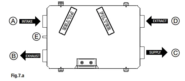
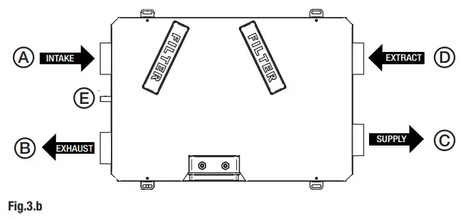
| A | Intake air from outside |
| B | Exhaust air outside |
| C | Supply air to inside |
| D | Extract air from inside |
| E | Condensation drainage |
7.1 3 speed operation with CTRL-V remote controller (supplied as standard)
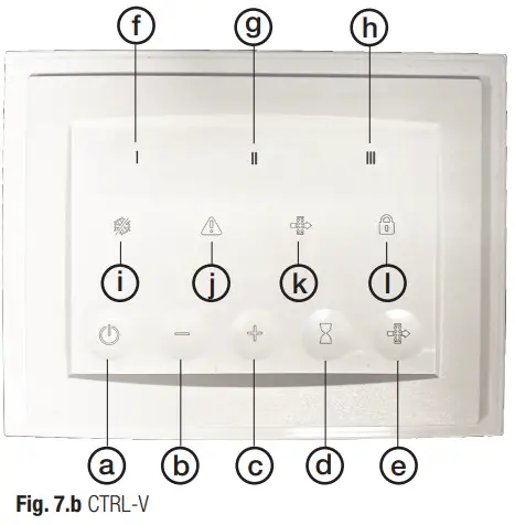
| a | to activate/deactivate the unit |
| b | to change the speed |
| c | to change the speed |
| d | to manually activate the Boost function |
| e | to reset the filter alarm |
| f | green led: speed 1 indicator |
| g | green led: speed 2 indicator |
| h | green led: speed 3 indicator |
| i | blue led: anti-frost activation indicator |
| j | red led: malfunction indicator |
| k | yellow led: filter maintenance/replacement indicator |
| l | yellow led: keypad lock indicator |
| FUNCTIONALITY | DESCRIPTION | TOUCH BUTTON | ICON | LED COLOUR |
| On/Off | ||||
| Pressing the touch button the unit activated/deactivated | – | – | ||
| Continuous running speed | ||||
| Speed I factory set is 40%: if necessary it can be adjusted by acting on the dip switch inside the terminal box as indicated in Fig. 6.a | + and – to change the speed | I | green | |
| Speed II factory set is 70%: if necessary it can be adjusted by acting on dip switch inside The terminal box as indicated in Fig. 6.a | + and — to change the speed | II | green | |
| Speed Ill factory set is 100%: if necessary it can be adjusted by acting on dip switch inside the terminal box as indicated in Fig. 6.a | a -I- and — to change the speed | III | green | |
| BOOST | ||||
| The unit will run at speed III for a fixed period of 15′. At the end of this time, the unit returns to the previously set speed. | IIII | green flashing | ||
| Alter reset | ||||
| Every 3 months the controller alerts the user to perform filter maintenance. By pressing the button for at least 1 second, the timing is reactivated | yellow | |||
| Antifrost | ||||
| The unit is equipped with a thermistor that, when necessary, reduces the speed of the inlet fan to prevent the formation of ice in the exchanger, which would irreparably damage the exchanger itself. When conditions return to normal, the function is automatically deactivated. | – | blue | ||
| Motor anomaly | ||||
| In case of a motor malfunction, the red led lights up. Contact technical assistance. | – | red | ||
| Keypad lock | ||||
| The CTRL-V buttons can be blocked. Keep the + and — buttons pressed contemporaneously for at least 5 seconds. Repeat this operation to unlock | + and — (keep pressed for at least 5 seconds) | yellow | ||
In the absence of alarms, the CTRL-V remote control goes into standby mode (no LEDs on) 3 minutes after the last button press.
7.2 Remote Enable
It allows to activate/deactivation of the unit from the remote by means of a volt-free contact by connecting the In1 input as per fig.5.k.
To enable this function it is necessary to act on dip switch 8.
| DIP8 | Remote Enable |
| 0 | disable |
| 1 | enable |
7.3 Modbus control
The unit can be controlled via Modbus (Modbus RTU over RS485). For specifications, contact our customer service.
MAINTENANCE AND SERVICE
WARNING
Make sure that specific warnings and cautions in Chapter 2 are carefully read, understood, and applied!
Maintenance can be carried out by the user.
Service must be performed only by an authorized installer and in accordance with local rules and regulations.
Questions regarding installation, use, maintenance, and service of the unit should be answered by your installer or place of purchase!
8.1 Components list
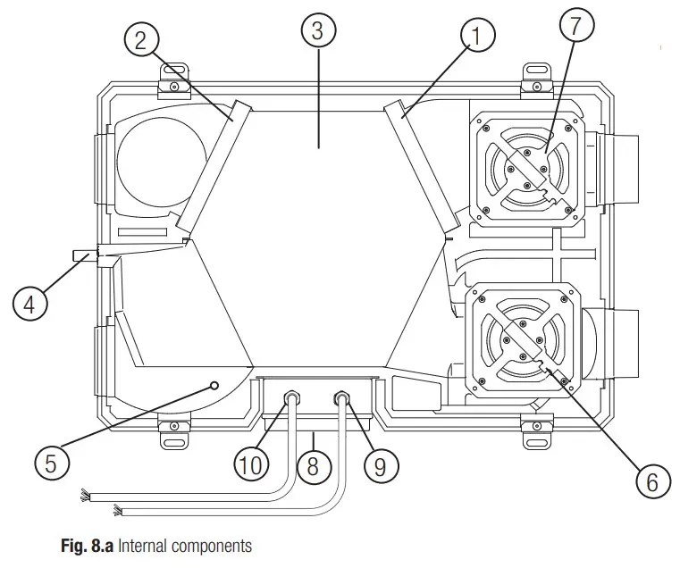
| 1 | G4 FILTER – EXTRACT AIR |
| 2 | G4 FILTER – SUPPLY AIR |
| 3 | HEAT EXCHANGER |
| 4 | CONDENSATION DRAINAGE |
| 5 | THERMISTOR |
| 6 | FAN, INTAKE AIR |
| 7 | FAN, EXHAUST AIR |
| 8 | TERMINAL BOX |
| 9 | CONTROL CABLE |
| 10 | POWER SUPPLY CABLE |
8.2 Description of Components
Fans
The fans have external rotor motors of EC type which can be steplessly controlled individually between 10-100%. The motor bearings are lifetime lubricated and maintenance-free. It is possible to easily disconnect and replace the fans if necessary.
Filters
The 2 filters are of filter quality G4 for both the supply air and extract air filter.
The filters need to be cleaned regularly (and replaced when polluted) during maintenance. New sets of filters can be acquired from your installer or wholesaler.
Heat exchanger
The unit is equipped with a highly efficient, counter-flow plate heat exchanger. Supply air temperature is therefore normally maintained without adding additional heat. The heat exchanger is removable for cleaning and maintenance during service.
Condensation drainage
Depending on the relative humidity in the extract air, condensation may occur on the cold surfaces of the heat exchanger, on one side in the winter time, on the other side in summer time (Table 6. b).
The condensate water is led out through a drainage pipe.
Thermistor
Temperature probe to implement temperature-dependent functions.
8.3 Maintenance
WARNING
Make sure that the mains supply to the unit is disconnected before performing any installation, service, maintenance or electrical work!
- Keep the unit surface free from dust.
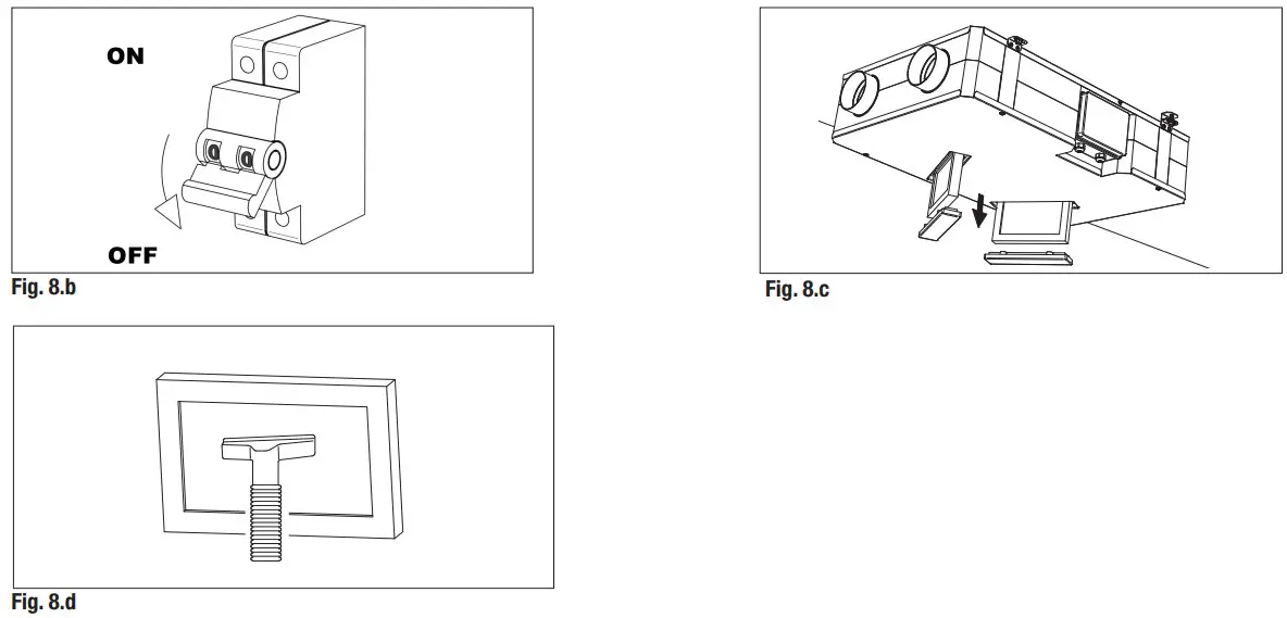
- Once every 3 months (fixed period), the unit warns the user to perform the filter maintenance (Fig. 7.b – ). The actual need to perform this operation may vary depending on indoor and outdoor ambient conditions.
- Clean the filters every 3 months with a vacuum cleaner (Fig. 8.b-c-d).
- Press the CTRL-V button (Fig. 7.b) to reactivate the filter alarm.
- Replace the filters every year.

8.4 Service
WARNING
Make sure that the mains supply to the unit is disconnected before performing any installation, service, maintenance or electrical work!
WARNING
The installation and service of the unit and complete ventilation system must be performed by an authorized installer and in accordance with local rules and regulations.
- Keep the unit surface free from dust.
- Once every 3 months (fixed period), the unit warns the user to perform the filter maintenance (Fig. 7.b – ). The actual need to perform this operation may vary depending on indoor and outdoor ambient conditions.
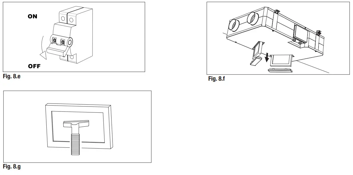
- Clean the filters every 3 months with a vacuum cleaner (Fig. 8.e-f-g).
- Press the CTRL-V button (Fig. 7.b) to reactivate the filter alarm.
- Replace the filters every year.

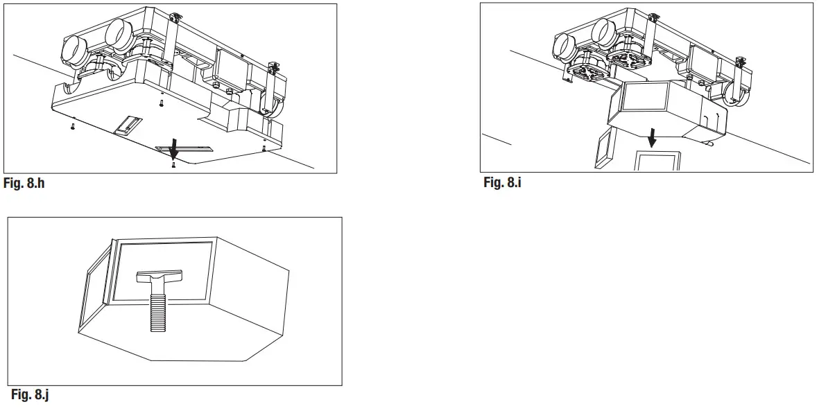
- Clean the heat exchanger every year with a vacuum cleaner. This may differ per situation depending on internal and external environmental conditions and on the frequency of filter cleaning (Fig. 8.e-h-i-j).

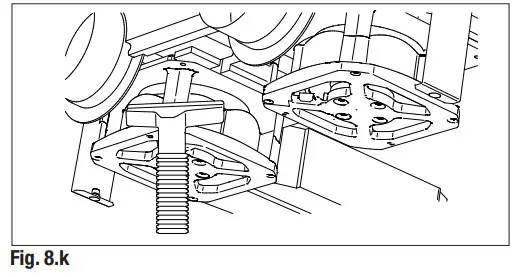
- Clean the fans every year with a vacuum cleaner. This may differ per situation depending on internal and external environmental conditions and on the frequency of filter cleaning. Do not move the balance clips of the fan (Fig. 8.e-h-k).

8.5 Troubleshooting
Fans do not start
- Check that the main supply gets to the unit.
- Check that all connections are working (all connections in the terminal box and fast couplings of intake and exhaust air fans).
Led on CTRL-V lights on
- Check paragraph 7
Reduced airflow
- Check the setting of fan speed in the terminal box or remote controller.
- Check filters. Change of filters required?
- Check diffusers. Re-setting or cleaning of grilles and diffusers required?
- Check fans and heat exchange block. Cleaning required?
- Check if the air intake and exhaust have been clogged.
- Check ducting system for damage and/or dirt accumulation.
Fan noise/vibrations
- Clean fan impellers. Cleaning required?
- Check that the fans are firmly in place within the unit.
Excessive air noise
- Check the setting of fan speed in the terminal box or remote controller.
- Check grilles and diffusers. Re-setting or cleaning of grilles and diffusers required?
Gurgling noise
- Drain connections have not been installed correctly.
- The drain connection has a too-low water level, fill it up with water.
Unpleasant smell
- Drain connections have not been installed correctly.
- The drain connection has a too-low water level, fill it up with water.
- Check filters. Change of filters required?
- Check ducting system and grilles and diffusers. Cleaning required?
Water leakage near the unit
- Drain connections have not been installed correctly. Checking necessary?
- Drain connections are dirty. Is cleaning necessary?
DISPOSAL AND RECYCLING
![]() Information on disposal of units at the end of life.
Information on disposal of units at the end of life.
This product complies with EU Directive 2002/96/EC.
The symbol of the crossed-out dustbin indicates that this product must be collected separately from other waste at the end of its life. The user must, therefore, dispose of the product in question at suitable electronic and electro-technical waste disposal collection centers, or else send the product back to the retailer when purchasing a new, equivalent type device.
Separate collection of decommissioned equipment for recycling, treatment, and environmentally compatible disposal helps to prevent negative effects on the environment and on health and promotes the recycling of the materials that make up the equipment.
Improper disposal of the product by the user may result in administrative sanctions as provided by law.
10. Direttiva ErP – Regolamenti 1253/2014 – 1254/2014
ErP Directive – Regulations 1253/2014 – 1254/2014
| a) | Math | AERAULIOA | |||
| b) | Model | – | CIR120P | ||
| c) | SEC class | A | A | B | |
| Cl) | SEC warm climates | kWh/1112.a | -14,7 | -11,3 | -8,5 |
| c2) | SEC average climates | Nohemi. a | -39,5 | -35,5 | -31,8 |
| c3) | SEC cold climates | kWWm2.a | -82,8 | -77,7 | -67,8 |
| Energy label | – | SiYes | |||
| s | Unit typology | Residential – bidirectional | |||
| e) | Type of drive | – | Variable speed drive | ||
| fl 1′ | Sistema di recupero calore Type of Heat Recovery System | A recipe Heat recovery | |||
| S | Thermal efficiency of heat recovery | % | 82 | ||
| h) | Maximum flow rate (0100Pa | m3/h | 102 | ||
| ,, ” | Electric premier Nut at a maximum flow rate | W | 58 | ||
| j) | Sound power level (Lts) | dBA | 50 | ||
| k) | Reference flow rate | m3/1) | 71 | ||
| „ ll | Reference pressure difference | Pa | 50 | ||
| E | Specific po vier input (SPI) | W/(m3/h) | 352 | ||
| n1) | Control factor | 0,65 | 0,85 | 1 | |
| n2) | Control typology | – | Local demand control | Central demand control | Manual control (no DCV) |
| n„ | Maximum internal leakage rate | % | 2 | ||
| A91 “`’ | Maximum external leakage rate | % | 1 | ||
| p1) | Internal mixing rate | % | N/A | ||
| p2) | External mixing rate | % | N/A | ||
| s | Visual filter warning | Visual filter warning on the display | |||
| r) | Instructions to install regulated grilles | N/A | |||
| s) | Internet address for pre/CFS assembly instructions | – | www.aerauliqa.it www.aerauliqa.com | ||
| t) | Airflow sensitivity to pressure variations | % | N/A | ||
| I | Indooriaddoor air tightness | m3/h | N/A | ||
| v1 | Annual electricity consumption – warm climates | kWh | 2,3 | 3,5 | 4,4 |
| v2) | Annual electricity consumption – average climates | kWh | 2,3 | 3,5 | 4,9 |
| v3) | AnnualOen/ally consumption – cold climates | kWh | 2,3 | 3,5 | 10,2 |
| mix | Annual heating sated – warm climates | kWh | 20,5 | 20,0 | 19,6 |
| I | Annual heating saved – average climates | kWh | 45,3 | 44,1 | 43,3 |
| w3) | – al hived – cold climates | kWh | 88,6 | 86,3 | 84,6 |
Registered office: via Mario Calderara 39/41, 25018 Montichiari (Bs)
C.F. e P.IVA/VAT 03369930981 – REA BS-528635
Tel: +39 030 674681 – Fax: +39 030 6872149 – www.aerauliqa.com – [email protected]
Aerauliqa Srl reserves the right to modify/make improvements to products and/or this instruction manual at any time and without prior notice.


