![]() 2479 00 Heating Ventilation Air Conditioning
2479 00 Heating Ventilation Air Conditioning
User Manual
Safety information
![]() Electrical devices may only be installed and connected by a qualified electrician.
Electrical devices may only be installed and connected by a qualified electrician.
Serious injury, fire or damage to property possible. Read and observe these instructions completely.
Danger of electric shock. Isolate before working on the device or load. In doing so, take all circuit breakers supplying dangerous voltage to the device or load into account. These instructions are an integral part of the product and must remain with the end customer.
Intended use
The terminal strip is for
- setting up a single-room control with up to 6 heating zones for heating and cooling systems,
- connecting up to 15 servos and 6 room temperature controllers,
- connecting servos with NC (normally closed) operation,
- connecting to an external timer,
- connecting to a pump, a heating/cooling switchover, a temperature limiter or dew point sensor,
- fixed installation.
Device components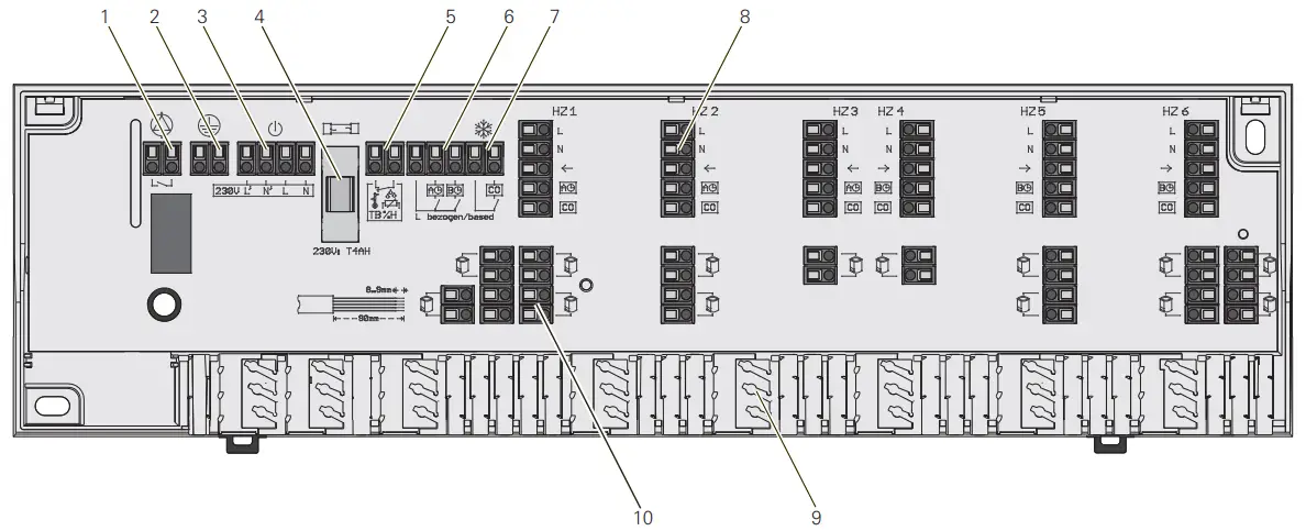
| 1. Pump connection | 6. Lowering temperature (ECO) via master clock |
| 2. Protective conductor connection | 7. Heating/cooling mode switchover |
| 3. Power supply | 8. Room temperature controller connection |
| 4. Fuse | 9. Strain relief |
| 5. Temperature limiter or dew point sensor | 10. Servo connection |
Installation
- Remove the cover.
- Mount the terminal strip.
In the case of wall mounting, secure the terminal strip with two Ø 4 mm screws and appropriate wall plugs depending on the wall structure and materials.
– or
Mount the terminal strip on the top-hat rail. - Establish the electrical connection, see “Electrical connection”.
- Mount the cover.
Technical data
| Operating voltage: | 230 V ±10%, 50 Hz |
| Power consumption: | 230 V, max. 50 VA |
| Protection: | T4AH |
| Number of heating zones: | 6 |
| Connectible servos | max. 15 |
| Switch-on current per servo: | max. 500 mA |
| Pump control switching capacity: | 2 A, 200 VA inductive |
| Operation: | NC |
| Ambient temperature: | 0 to +50 °C |
| Storage temperature: | -20 to +70 °C |
| Ambient humidity: | 80% non-condensing |
| Temperature ball thrust test: | Connection terminals: 100 °C Plastic housing: 75 °C |
| Pollution level: | 2 |
| Rated surge voltage: | 1500 V |
| IPC class according to EU 811/2013: | 1=1% |
| Protection class: | II |
| Protection type: | IP 20 |
| Mode of action: | Type 1.C |
| Dimensions (H x L x D): | 90 x 326.5 x 50 mm |
Electrical connection![]() DANGER!
DANGER!
Risk of death from electric shock.
Disconnect the device. Cover any live parts.
- The cable cross-sections must measure 1.5 mm² for connecting the power supply.
- A temperature limiter/dew point sensor can be connected on contact TB/%H. If this contact is not used, it must be bridged (performed at the factory). As soon as a connection is made at contact TB/%H, the bridge must be removed. The temperature limiter/dew point sensor must be designed as a normally closed contact.
- The connected room temperature controller and servos must match the connected supply.
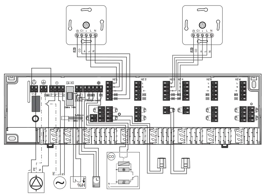
| Room temperature controller | |
| Servo | |
| Pump | |
| Power supply | |
| Temperature limiter/dew point sensor | |
| System clock | |
| Heating/cooling mode switchover | |
| Cooling | |
| Heating |
Warranty
The warranty is provided in accordance with the statutory requirements via the retailer.
Please submit or send faulty devices postage paid and with a fault description to your sales representative (retailer / installation company / electronics retailer). They will forward the devices to the Gira Service Centre.
| Operating instructions | Gira Giersiepen GmbH & Co. KG Elektro-InstallationsSysteme |
| Terminal strip, 6-gang 230 V 2479 00 | Industriegebiet Mermbach Dahlienstrasse 42477 Radevormwald P. O. Box 12 20 42461 Radevormwald Germany |
| Heating, ventilation, air conditioning | Tel +49(0)21 95 – 602-0 Fax +49(0)21 95 – 602-191 www.gira.de [email protected] |