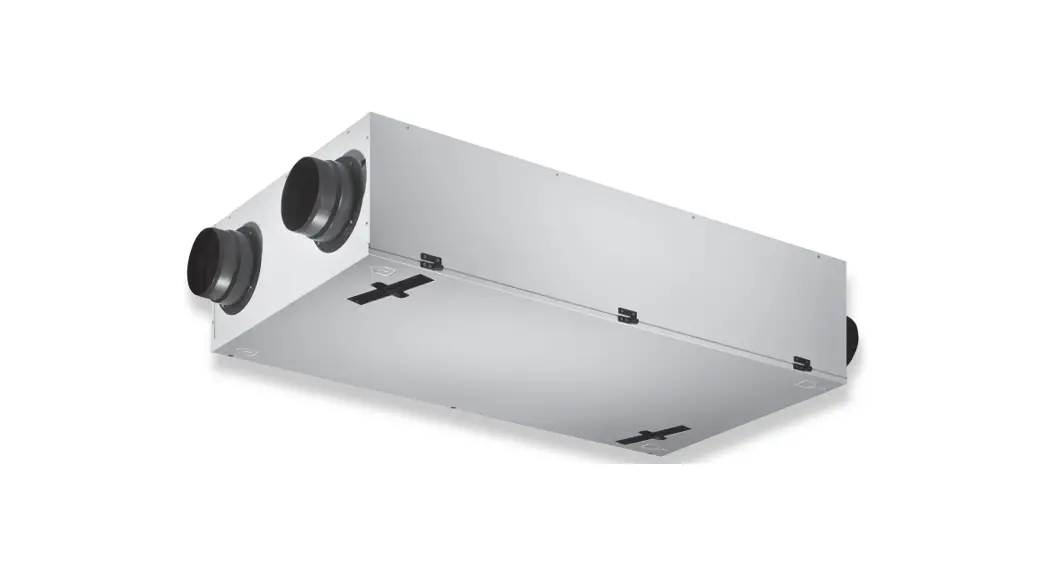
![]() Renovent Sky 300 (Plus)
Renovent Sky 300 (Plus)
INSTALLATION INSTRUCTIONS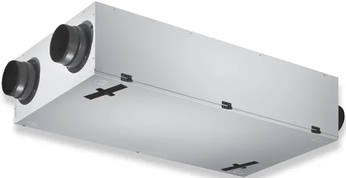
Sky 300 Mechanical Ventilation with Heat Recovery
This appliance can be used by children aged from 8 years and above and persons with reduced physical, sensory or mental capabilities or lack of experience and knowledge if they have been given supervision or instruction concerning use of the appliance in a safe way and understand the hazards involved. Children shall not play with the appliance. Cleaning and user maintenance shall not be made by children without supervision.
Chapter 1 Delivery
1.1 Scope of delivery
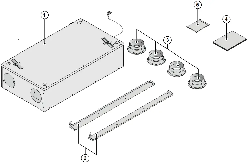
Before starting installation of the heat recovery unit, check that it has been supplied complete and undamaged.
The scope of delivery of the heat recovery unit Renovent Sky 300 includes the following components:
| 1: Heat recovery appliance | – 2x suspension strips |
| 2: Wall mounting bracket kit; | – 4x collars Ø150/160 mm |
| 3: Duct connecting kit; | – 1x installation instructions |
| 4: Documentation set; | – Mounting material collars, including 16 fixation screws |
| 5: Connecting kit; | – Connectors : 2-pole screw connector (eBus) and 9-pole screw connector (only for Plus version) |
1.2 Accessories Renovent Sky 300
| Electric postheater | 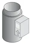 | 310671 |
| Electric (extra) preheater | 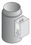 | 310681 |
| Splitter RJ12 | 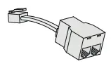 | 510472 |
| CO2 |  | 532126 |
| sensor E-Bus surface-mounted | 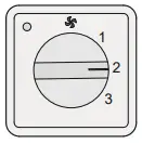 | 540262 |
| Transmitter wireless remote control 2 positions (with. battery) |  | 532170 |
| Transmitter wireless remote control 4 positions (with. battery) |  | 532171 |
| Receiver wireless remote control (for battery version) | 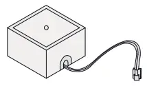 | 532172 |
| Kit wireless remote control 2 positions (1 transmitter & 1 receiver) | 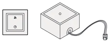 | 532173 |
| Kit wireless remote control 4 positions (1 transmitter & 1 receiver) | 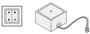 | 532174 |
| RH (humidity)-sensor | 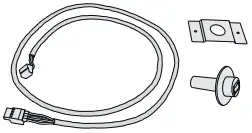 | 310657 |
| Filterset 1*ISO ePM 1 50% (F7) filter (1 Pcs) | 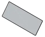 | 532001 |
| Filterset 1x ISO Coarse 60% (G4) & 1x ISO ePM 1 50% (F7) (2 pcs) | 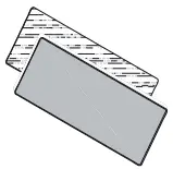 | 532002 |
| Servicetool | 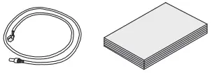 | 531961 |
| Enthalpie heat exchanger | 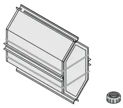 | 532060 |
| Demperunit 2 x Ø160 mm | 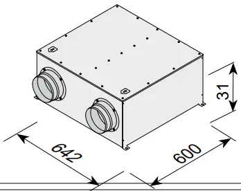 | 422500 |
| Demperunit 18 x Ø75 mm | 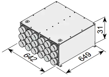 | 422501 |
| Demperunit 18 x 100 – 50 mm | 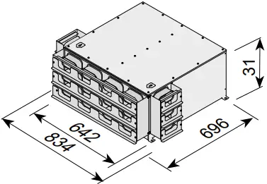 | 422502 |
| Demperunit 12 x 130 – 60 mm | 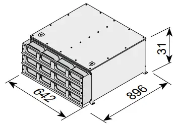 | 422503 |
Chapter 2 Application
The Brink Renovent Sky 300 is a ventilation unit with heat re-covery with an efficiency of 95%, a maximum ventilation capac-ity of 300 m3/h and low-energy fans. Features Renovent Sky:
- steplessly adjustable air flow rates through a “Brink Air Con-trol” (supplied with appliance).
- filter indication on the “Brink Air Control” / multiple switch.
- a completely new intelligent frost protection system which ensures that also at low outdoor temperatures the appli-ance’s performance remains optimal and that, if necessary, it activates the optional preheater.
- low sound level
- comes as standard with automatic bypass valve
- constant flow control
- low energy consumption
- high efficiency
Renovent Sky 300 is available in two types:
- “Renovent Sky 300”
- “Renovent Sky 300 Plus”
Compared to the Renovent Sky 300, the Renovent Sky 300 Plus has a more extensive control board which increases the connection options.
These installation instruction describe both the standard Reno-vent Sky 300 and the Renovent Sky 300 Plus.
With the aid of the supplied mounting brackets, the Renovent Sky 300 (Plus) can be mounted either on the wall or on the ceiling. For the correct position of the connection ducts and dimensions see §3.2.
When ordering an appliance always state the correct type; subsequent conversion to a different version is highly labour-intensive.
The Renovent Sky 300 comes ready to plug in with a 230 V mains plug.
The appliance comes as standard with a “Brink Air Control”, but connection of a simple 4-way switch is possible as well. If a 4-way switch is installed instead of a “Brink Air Con-trol”, the settings of the appliance can only be changed with a laptop!
Connecting a combination of “Brink Air Control” and multiple switch is another option.
Chapter 3 Version
3.1 Technische specifications
| Renovent Sky 300 | |||||
| Supply voltage [V/Hz] | 230/50 | ||||
| Protection degree | IP30 | ||||
| Dimensions (w x d x h) [mm] | 1185 x 644 x 310 | ||||
| Duct diameter [mm] | 0150 / 0160 | ||||
| External diameter condensate discharge [mm] | 32 | ||||
| Weight [kg] | 37 | ||||
| Filter class | ISO Coarse 60% (G4) | ||||
| Fan setting (factory setting) -“Brink Air Control” | Max | ||||
| 4-way switch | |||||
| Ventilation capacity [m3/h] | 50 | 100 | 150 | 225 | 300 |
| Permissible resistance ducts system [Pa] | 3 – 6 | 11 – 26 | 25 – 58 | 56 – 129 | 100 – 230 |
| Rated power (excl. optionel preheater) [W] | 8,7 – 9,1 | 14,9 – 16,3 | 25,7 – 31,7 | 57,8 – 77,8 | 116,1 – 162,9 |
| Rated current (excl. optionel preheater) [A] | 0,10 | 0,15 – 0,17 | 0,25 – 0,29 | 0,50 – 0,66 | 0,95 – 1,34 |
| Rated power (incl. optionel preheater) [W] | 6 | ||||
| Cos (f) | 0,39 | 0,42 | 0,45 – 0,47 | 0,50 – 0,51 | 0,53 |
| Sound power Sky 300 | ||||||||||
| Ventilation capacity [m3/11] | 100 | 150 | 225 | 300 | ||||||
| Sound power level Lw (A) | Static pressure [Pa] | 17 | 40 | 38 | 80 | 84 | 100 | 160 | 150 | 178 |
| Housing emission [dB(A)] | 29 | 30 | 37 | 40 | 46 | 46 | 47 | 53 | 53 | |
| Duct “from dwelling” [dB(A)] | 32 | 32 | 41 | 43 | 49 | 49 | 50 | 55 | 55 | |
| Duct “to dwelling” [dB(A)] | 43 | 44 | 51 | 53 | 60 | 61 | 62 | 69 | 68 | |
In practice, the value may deviate 1 dB(A) as a result of measuring tolerances.
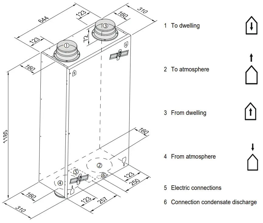
3.2 Connections and dimensions
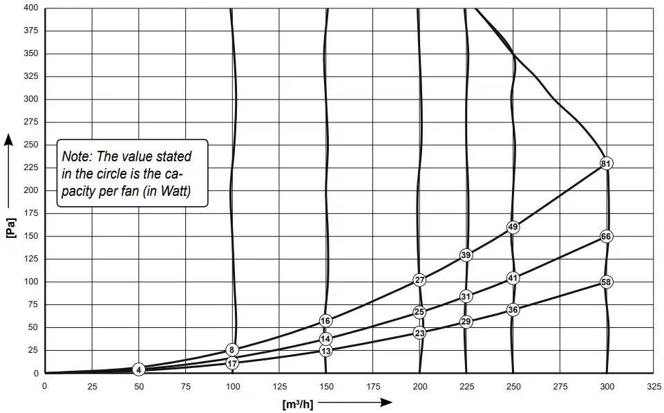
3.3 Fan graph
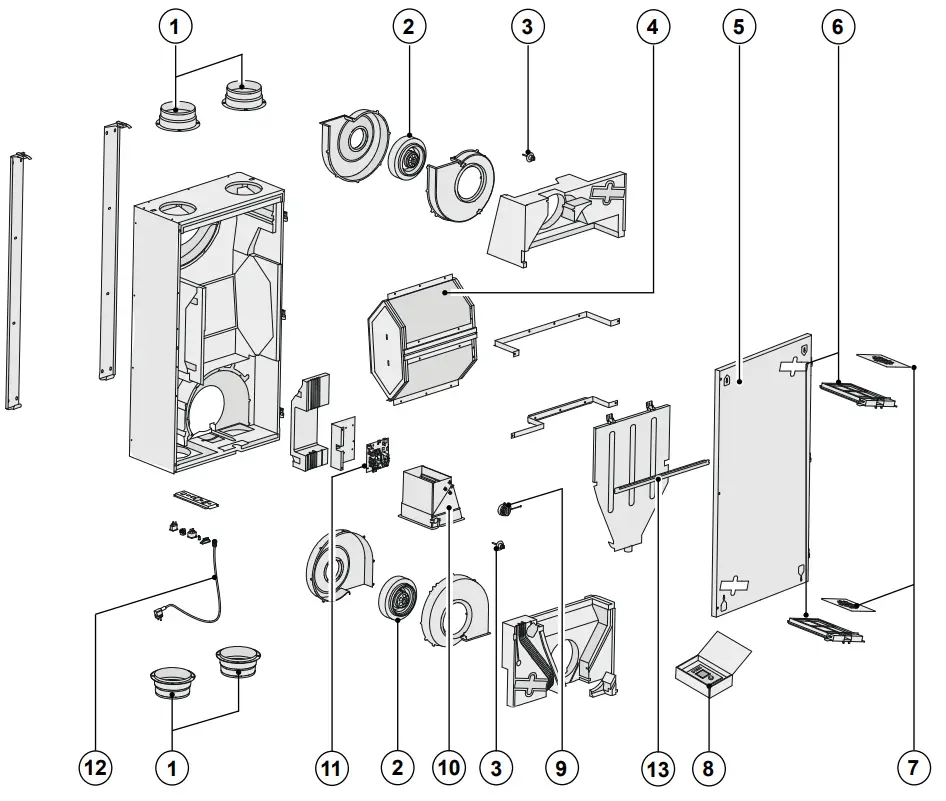
3.4 Exploded view
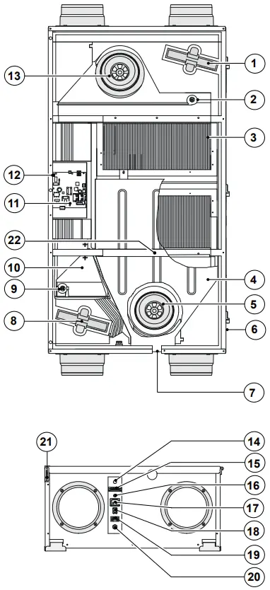
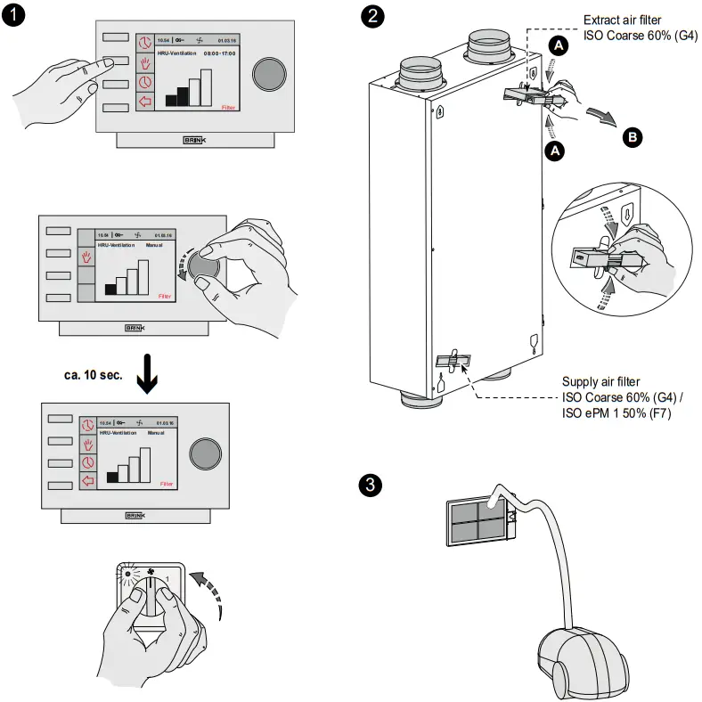
| 1 | Extract air filter |
| 2 | Indoor temperature sensor |
| 3 | Heat exchanger |
| 4 | Condensate bin |
| 5 | Extract fan |
| 6 | Locking screw front panel (mounted in front panel) |
| 7 | Condensate discharge |
| 8 | Supply air filter |
| 9 | Outdoor temperature sensor |
| 10 | Bypass |
| 11 | Control board |
| 12 | Connector X14 |
| 13 | Supply fan |
| 14 | Sleeve cable 230 V. postheater or extra preheater |
| 15 | 9-pole connector (only for Plus version) |
| 16 | Service connector |
| 17 | Connection 230V preheater |
| 18 | Modular connector multiple switch |
| 19 | Connector eBus |
| 20 | Mains cable 230 V. |
| 21 | Fall protection front panel |
| 22 | Mounting strip |
Chapter 4 Operation
4.1 Description
The appliance comes plug and play and operates fully automatically. The extracted indoor air heats up the fresh, clean outdoor air. That saves energy and fresh air is sent to the required rooms.
The control system has four ventilation modes.
The air flow rate can be adjusted per ventilation mode. The constant volume control system ensures that the air flow rate of the supply and extract fans is realised independent of the duct pressure.
4.2 Bypass conditions
The standard bypass valve makes it possible to supply fresh outside air that is not heated by the heat exchanger. Particular-ly during summer nights it is desirable to supply cooler outside air. Then the hot air in the dwelling is replaced by cooler outside air in so far as possible.
The bypass valve opens and closes automatically when a num-ber of conditions are satisfied (refer to the table below for by-pass conditions). The operation of the bypass valve can be adjusted in step num-ber 5, step number 6 and step number 7 in the settings menu (see chapter 12).
| Bypass valve open | – The outdoor temperature is higher than 7°C and – the outdoor temperature is lower than the indoor temperature in the dwelling and – the temperature in the dwelling is higher than the temperature set at step no. 5 in the settings menu (set a standard at 22°C). |
| Bypass valve closed | – The outdoor temperature is lower than 7°C or – the outdoor temperature is higher than de indoor temperature in the dwelling or – the temperature from the dwelling is lower than the temperature set at step no. 5 in the settings menu minus the set temperature by the hysteresis (step no. 6), this temperature is factory 20 °C (22,0 °C minus 2,0 °C).. |
4.3 Frost protection
To prevent freezing of the heat exchanger at extremely low outdoor temperatures, the Renovent Sky features intelligent frost control. Temperature sensors measure the temperatures across the heat exchanger and, if necessary, the preheater is switched on. That guarantees a proper ventilation balance, also at very low outdoor temperatures. If, with switched on preheater(s), the exchanger temperature still starts to drop below zero, steplessunbalance is created in the appliance.
The user information menu shows when the Renovent Sky frost control system is activated (see § 6.4).
The Renovent Sky is also available as Plus version. This verconnectors (X14 & X15) with more connection options for various applications.
Only the Plus is equipped with a 9-pole connector (connected to X15 on control board) that is accessible from the outside of the appliance.
If a postheater or extra preheater is connected to connector X14 (accessible after opening the front panel) the installer must feed the connected 230 Volt cable to outside the appliance through a strain reliever. For this strain reliever (not supplied with the appliance) a plug must be removed from the position where this strain relieve must be placed.
See §9 for more information on the connection possibilities of connectors X14 and X15.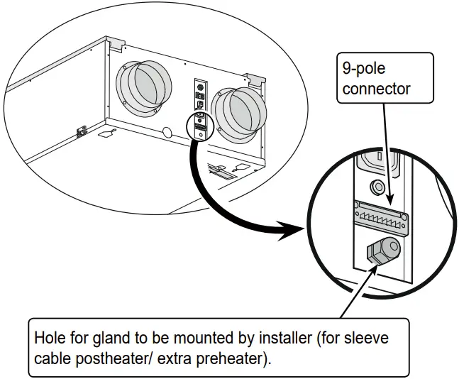
Chapter 5 Installation
Installation must take place under:
- Quality requirements ventilation systems dwellings.
- Quality requirements balanced ventilation in dwellings.
- The regulations for ventilation of dwellings and residential buildings.
- The safety regulations for low-voltage installations.
- The regulations for connection to interior sewers in dwell-ings and residential buildings.
- Any additional regulations of the local utilities.
- The installation instructions for the Renovent Sky 300
- In addition to the above design and installation requirements and recommendations, the national building and ventilation regulations must be complied with.
5.1 Installation general
Installation must take place under:
- Quality requirements ventilation systems dwellings.
- Quality requirements balanced ventilation in dwellings.
- The regulations for ventilation of dwellings and residential buildings.
- The safety regulations for low-voltage installations.
- The regulations for connection to interior sewers in dwell-ings and residential buildings.
- Any additional regulations of the local utilities.
- The installation instructions for the Renovent Sky 300
- In addition to the above design and installation requirements and recommendations, the national building and ventilation regulations must be complied with.
5.2 Placing the appliance
The Renovent Sky 300 can directly be mounted to the wall or ceiling using the mounting brackets supplied for that purpose.![]() Because of the appliance’s weight, mounting the appliance must always be done by two people!
Because of the appliance’s weight, mounting the appliance must always be done by two people!
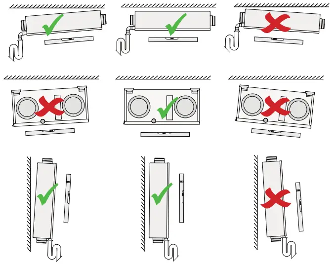
The Renovent Sky can directly be mounted to the wall/ ceiling using the suspension brackets supplied for that purpose. For a vibration-free result the appliance must be mounted to a solid wall with a minimum mass of 200 kg/m2. A gypsum block or metal stud wall does not suffice! Additional measures such as double panelling or extra studs are required in that case. In ad-dition, the following aspects must be taken into account.
- The appliance must be placed level.

- The installation room must be such that a good conden-sate discharge with air trap and pitch for condensate can be made.
- We recommend not to install the heat recovery unit in spaces with an average high RH (for instance bathroom). That will prevent condensation on the outside of the heat recovery unit.
 Make sure that under no condition the condensate discharge is installed at a pitch towards the appli-ance! The appliance is only suitable for ceiling or wall mounting! Never mount the appliance flat on the floor because of the position of the condensate discharge bin!
The heat recovery unit must be installed in an insulated, frost-free room to prevent, among other things, freezing of the condensate discharge - When mounting flexible ducts, bear in mind that it must be possible to replace them in due course.
- Make sure there is sufficient free space at the appliance to allow cleaning of the filters and maintaining the appliance. It must be possible to swing the door open.
- Avoid the use of petroleum-based adhesives in air plant systems.
- Dwellings with construction moisture must be ventilated naturally during a certain period!
Ceiling mounting:
At least 70 cm at the underside of the appliance and a free headroom of 1.8 m; if 70 cm free space is not available, for instance when mounting on top of a suspended ceiling, there must be sufficient room to partly open and remove the front panel.
The front panel can be detached after removing a lock screw at the hinge! (§ 3.4 / nr. 6)
Make sure the filters can always freely be removed, so there is no frame or other obstacle at the level of the filters!
Wall mounting:
Make sure there is a free space of at least 70 cm at the front of the appliance and a free headroom of 1.8 m. - Make sure there is at least 20 cm free space at the appliance side where the electric connections are located, so connectors and sleeves remain accessible.
Air ducts:
- The air ducts must be mounted air-tight
- The air ducts to and from the dwelling must be fitted with a muffler.
- Mounting of air ducts to the roof deck must be avoided in order to prevent sound transmission.
- It is recommended to restrict the external duct pressure in the design to 100 Pa at the design flow rate in order limit the total sound level. In all events the practical external duct pressure must be limited to 150 Pa
- The air velocity must be limited to 5 m/s in the main ducts and 3,5 m/s in the branches.
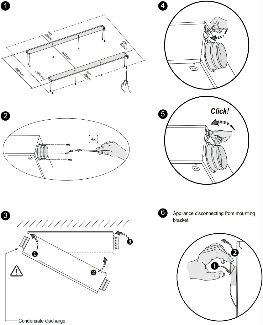
5.2.1 Placing the appliance for ceiling mounting
 5.2.2 Placing the appliance for wall mounting
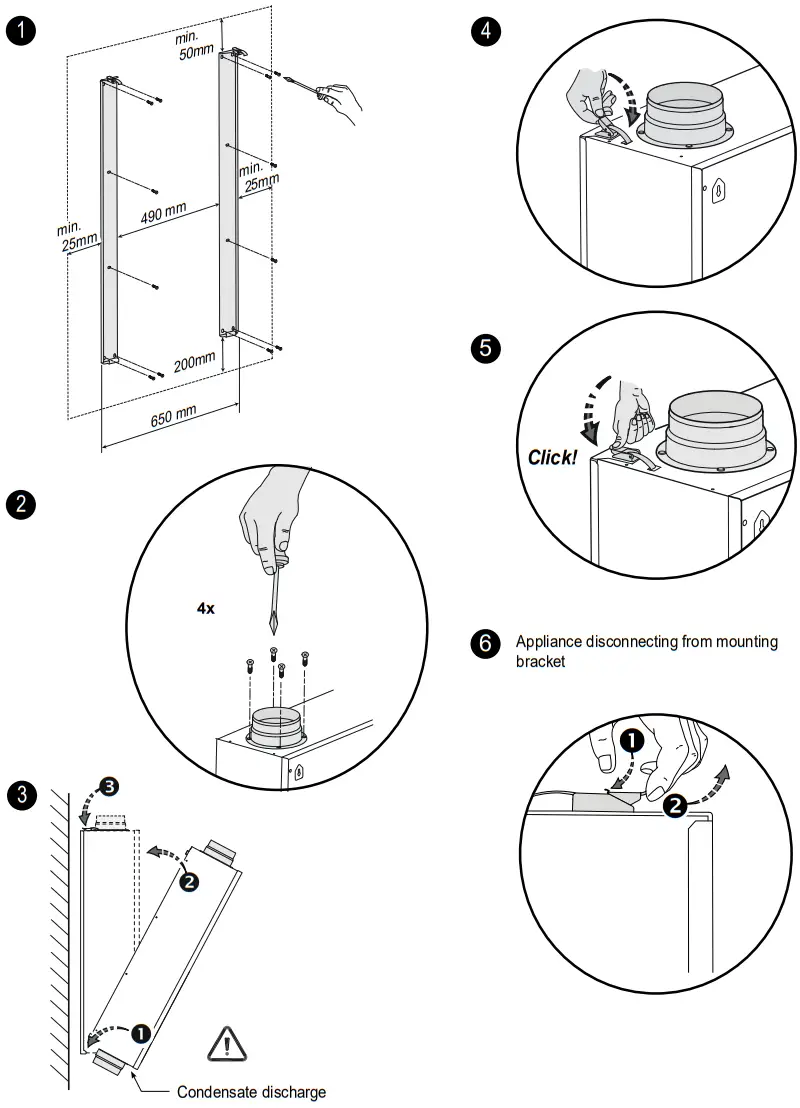
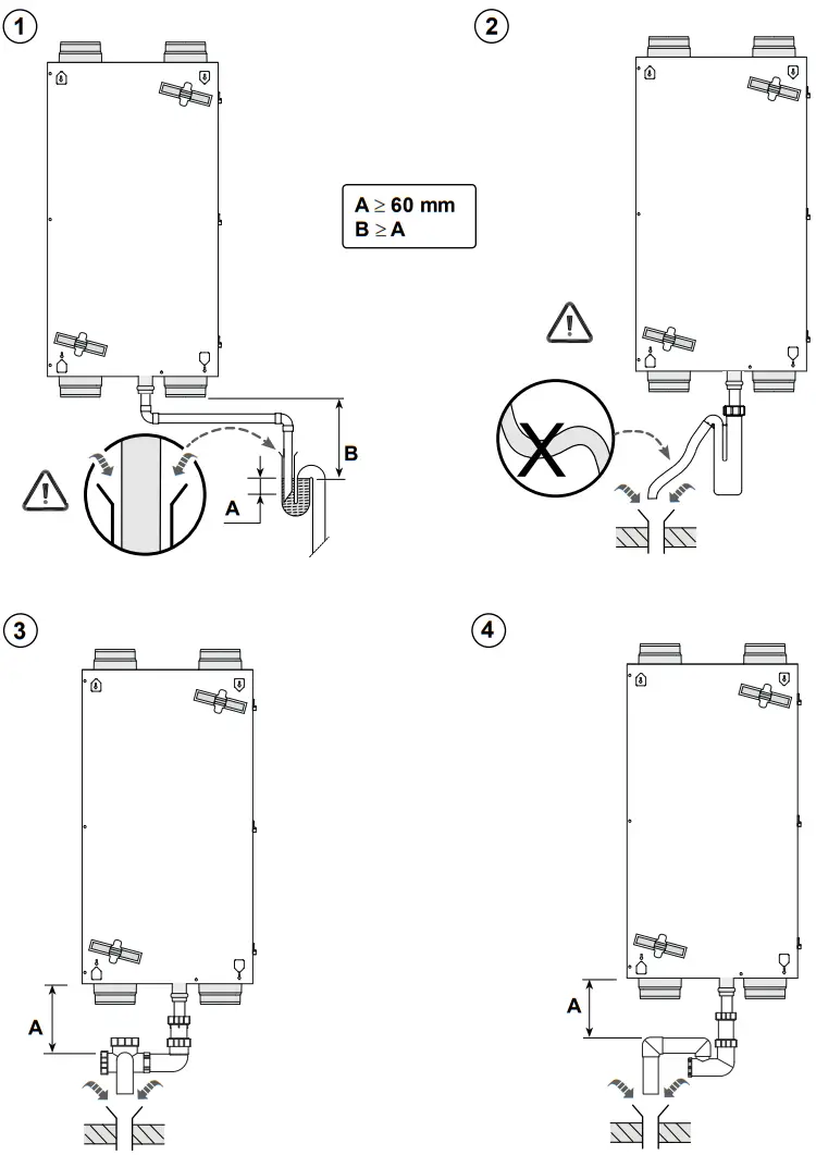
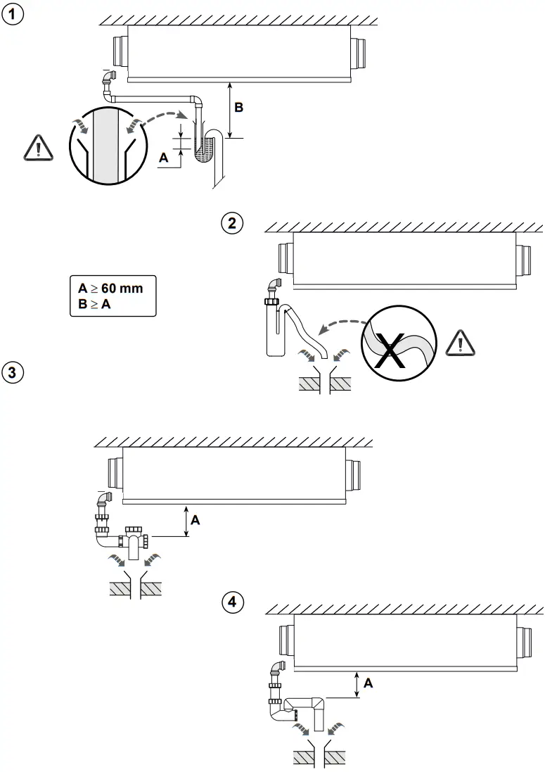
5.3 Connecting the condensate discharge
The Renovent Sky must always be fitted with a condensate discharge. The condensate must be discharged through a drainpipe
The condensate discharge must be connected using a 32 mm condensate line with plug-in sleeve and sealing ring (HT DN32) (not supplied with the appliance). Do not use a glued or screwed connection here!
Important:![]() Always apply a lubricant (for instance acid-free petroleum jelly) on the rubber sealing ring in the sleeve prior to assembly. That allows disassembly of the sleeve connection when servicing the appli-ance!
Always apply a lubricant (for instance acid-free petroleum jelly) on the rubber sealing ring in the sleeve prior to assembly. That allows disassembly of the sleeve connection when servicing the appli-ance!
The condensate discharge can for instance be connected using a straight or elbow sleeve fitting. Slide the sleeve fitting into the appliance with sufficient length over the condensate bin socket to ensure a leakage-proof seal. The drain must discharge un-der the water level in the U-trap. Use a condensate discharge line with a diameter of 32mm.
Particularly for ceiling mounting, make sure the conden-sate discharge is below the level of the condensate bin in the Renovent Sky!
Before connecting the condensate discharge to the appliance, pour water into the U-trap to create an air trap.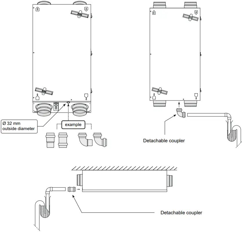
5.4 Electric connections
5.4.1 Connecting the power plug
The appliance can be connected to an easily accessible, earthed wall socket with the plug that is mounted to the appliance. The electric installation must comply with the requirements of your power company.
The appliance comes ready to plug in with a 230 V mains plug
Make allowance for the 1000 W preheater; if in addition also a postheater or extra preheater is installed, the rated power increases to 2000 W.
Warning![]() The fans and control board carry a high voltage. Al-ways take the voltage from the appliance by pulling the power plug when working on the appliance.
The fans and control board carry a high voltage. Al-ways take the voltage from the appliance by pulling the power plug when working on the appliance.
5.4.2 “Brink Air Control” connection
The “Brink Air Control” that comes as standard with the appli-ance must be connected to the eBus connector. This (detachable) 2-pole eBus connector is mounted on the outside of the appliance (see also §10.1). 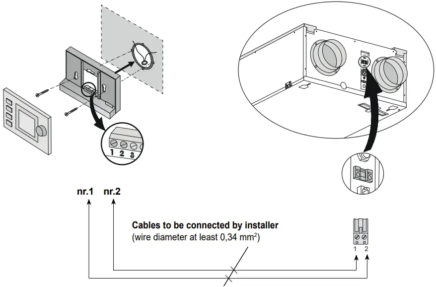
Chapter 6 Display
6.1 Switching the appliance on and off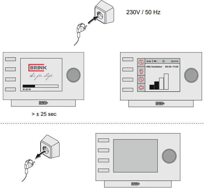
Warning![]() When working on the appliance, always take the voltage from the appliance by first switching it off through software and subsequently pulling the power plug.
When working on the appliance, always take the voltage from the appliance by first switching it off through software and subsequently pulling the power plug.
6.2 General explanation Brink Air control
The “Brink Air control” display shows what the operating mode of the appliance is. Settings in the “Brink Air control” software of the Renovent Sky can be called up and changed with the aid of the operating keys. Ex factory the “Brink Air Control” is set for the English language. In the setting menu “Brink Air Control”, §6.4.2, you can choose a language. 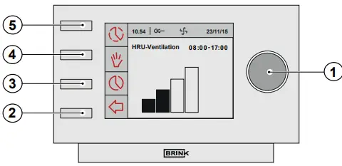
| 1. | Setting tting knob | Pressing the Right-hand setting knob’ takes you to the Main Menu of the Sky appliance (§6.4). |
| 2. | Return key | Press the Return key ( |
| 3. | Setting & activating timer programme | Use this key ( |
| 4. | Manual control key | After pressing the manual control key ( |
| 5. | Bypassing the timer programme | Pressing the key ( |
6.3 View on Display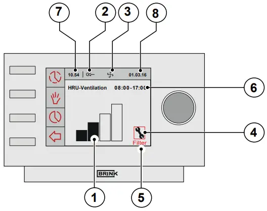
When the Renovent Sky is in operating mode, the “Brink Air control” display indicates a number of different values:
- Flow rate indicator
- eBus connection indicator
- Fan indicator
- Fault symbol
- Filter message
- Current time block
- Current time
- Current date (day / month / year)
- The display shows a bar chart (flow rate indicator) of the current ventilation rate.
Flow rate indicator 4-way switch 

The supply and extract fans are running at 50 m3/h or they are stopped (step number 1). 
1 The supply and extract fans are running in ventilation mode 1 (step number 2). 
2 The supply and extract fans are running in ventilation mode 2 (step number 3) 
3 The supply and extract fans are running in ventilation mode 3 (step number 4) - This eBus indicator appears when the eBus connection is active; if it is not visible, no communication is possible between the “Brink Air control” and the Sky appliance.
- This ventilation indicator appears when the fans in the appliance are running.
- This fault symbol appears when an appliance fault has occurred.
- When the text “Filter” appears on the “Brink Air control” display, the filters in the appliance must be cleaned or replaced.
- This indicates in what (preprogrammed) time interval the appliance is.
When the manual control key ( ) or temporary bypassing of the timer programme (
 ) its activated, the time interval picture disappears and is replaced by the message “Manual or Temporary”.
 - The current time is shown at this position. It is important for proper performance of the appliance that the time is set correctly.
- The current date is shown at this position.
6.4 Main menu
Pressing the right-hand setting knob on the “Brink Air control” takes you to the MAIN MENU.
In this main menu you can use the right-hand setting knob to select one of the 3 available manuals (rotate to select and press to confirm) including: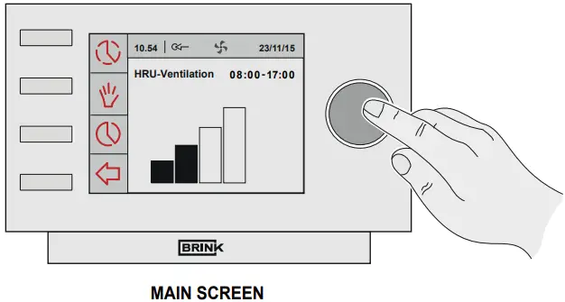
- Device information §6.4.1
- Basic settings §6.4.2
- Installer §6.4.3
Selected menus can be closed by pressing the return key (![]() ); if the return key (
); if the return key (![]() ) is not pressed, the display will return to the main screen some 5 minutes after the last time a key is operated.
) is not pressed, the display will return to the main screen some 5 minutes after the last time a key is operated.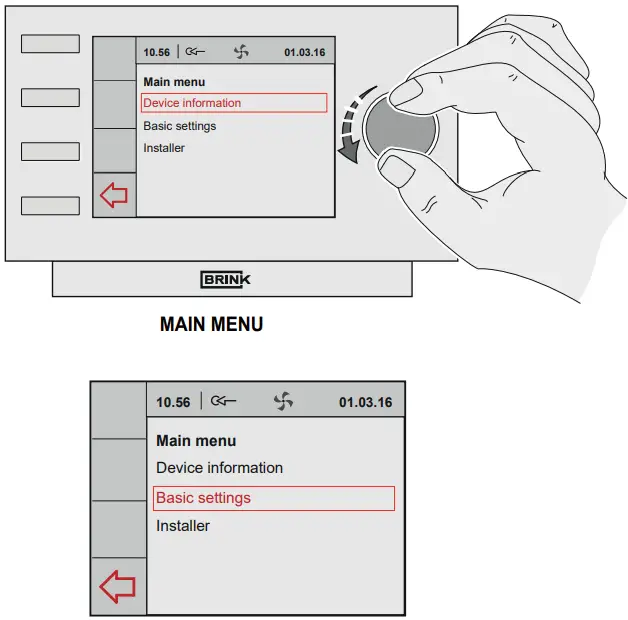 6.4.1 Device information menu
From the main menu, turn the right-hand setting knob to select the “Device information” menu and confirm the selection by pressing the right-hand setting knob.
If several appliances are connected, a selection from the appliances can be made in this menu; if only a Sky appliance is connected, then select HRV appliance:
– HRU-appliance
Turning the right-hand setting knob calls up the various current values. Modifying values or settings is not possible in this menu!
Selected menus can be closed by pressing the return key (![]() ); if the return key (
); if the return key (![]() ) is not pressed, the display will return to the main screen some 5 minutes after the last time a key is operated.
) is not pressed, the display will return to the main screen some 5 minutes after the last time a key is operated.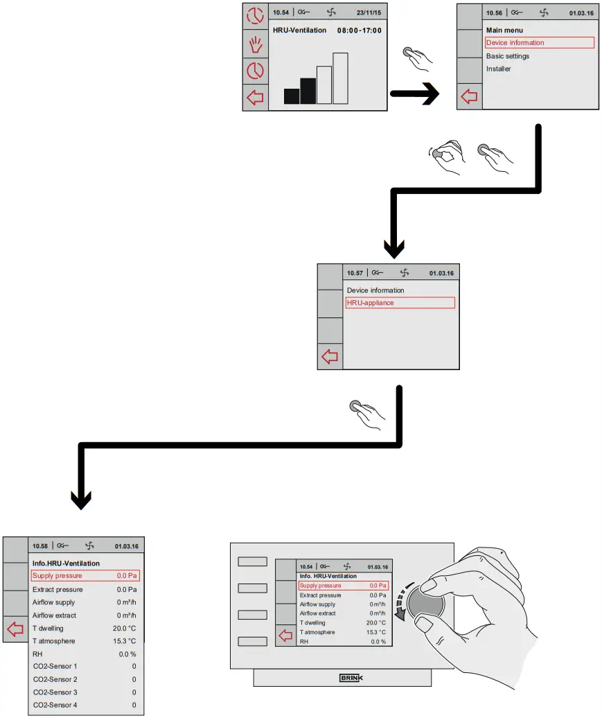 6.4.2 Basic settings menu
From the main menu, turn the right-hand setting knob to select the “Basic settings’ menu and confirm the selection by pressing the right-hand setting knob. In this menu, you
can select from five submenus, including:
- Language
- Clock
- Date
- Backlight
- Key lock
(A) Language
In this menu you can choose a language; ex factory the “Brink Air Control” is set for the English language. The optional languages are: Dutch/English/German/French/ Italian/Spanish/Polish/Lithuanian /Danish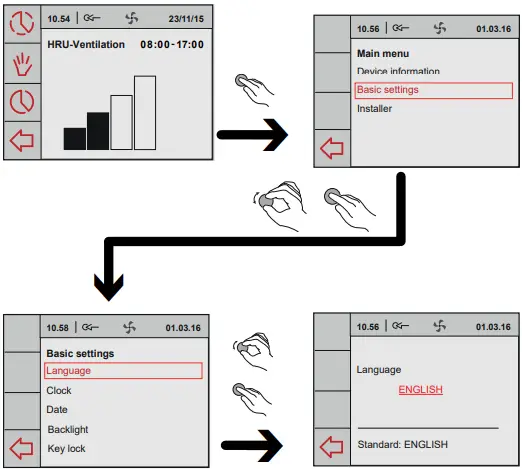 (B) Clock
The current time must be set in this menu.
The time is always shown in 24 hours mode.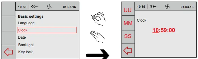 (C) Date
The current date must be set in this menu; the day, month and year must be entered.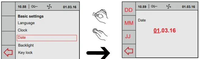 (D) Backlight
In this menu the display backlighting can be adjusted.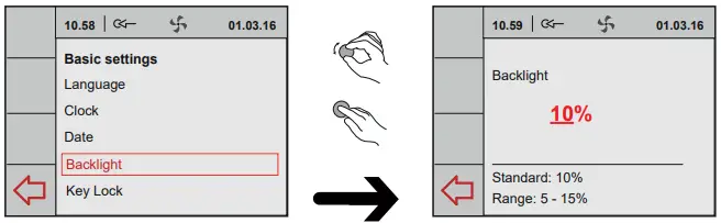 (E) Key lock
This can be used to prevent unwanted use and the changing of settings.
It will become active 1 minute after the last setting has been made.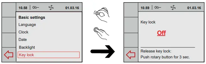 Deactivate the key lock once-only by holding down the right-hand setting knob for 3 seconds!
Permanently deactivate it by changing the setting in the key lock menu.
6.4.3 Installer menu
From the main menu, turn the right-hand setting knob to select the “Installer”
by pressing the right-hand setting knob.
If several appliances are connected, a selection from the appliances can be made in this menu; if only a Sky appliance is connected, then select HRV appliance:
– HRU-appliance
From this menu can be chosen from:
A Device settings
B Factory setting
A. Device settings
Selecting parameter takes you to the overview of all step numbers of the appliance as described in chapter 12. In this menu you can view these values and, if necessary, modify them.![]() Incorrect settings may se-riously affect the proper performance of the appli-ance!
Incorrect settings may se-riously affect the proper performance of the appli-ance!
B. Factory setting
Selecting factory setting will restore all step numbers to the original fac-tory setting. All fault messages will be deleted as well. 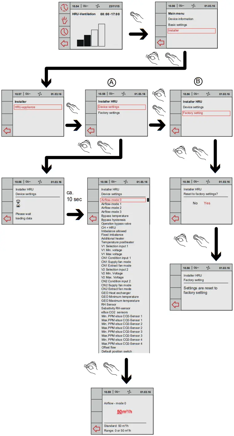
Chapter 7 Fault
7.1 Trouble shooting
When the appliance control system detects a fault, it is indicated on the display of the “Brink Air control” with a spanner symbol, possibly together with a fault code.
Non-locking fault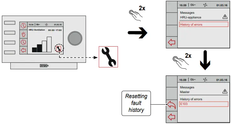 When the appliance detects a non-locking fault, it will still keep running (limitedly).
The display does show the fault symbol (spanner).
This fault can be read out in the menu “Messages”.
Locking fault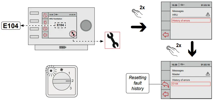 When the appliance detects a locking fault, it will no longer work. The (permanently lighted) display shows the fault symbol (spanner) together with fault code. The red LED on the multiple switch (if applicable) will be blinking. Contact the installer to remedy this fault. A locking fault cannot be remedied by taking
![]() Warning
Warning
When working on the appliance, always take the voltage from the appliance by first switching it off through software and subsequently pulling the power plug.
7.2 Display codes
| Fault code | Cause | Action appliance | Action installer |
| E100 | Pressure sensor supply fan defective. Red pressure hoses blockedor “kinked” | – Switches to constant rpm control. – The preheater switches on at outdoor temperatures below 0°C. | • Take the voltage from the appliance. • Check the red pressure hoses (and pressure tubes) for fouling, kinking and damage |
| E101 | Pressure sensor extract fan defective. Blue pressure hoses blocked or “kinked” | – Switches to constant rpm control. – The preheater switches on at outdoor temperatures below 0°C | • Take the voltage from the appliance. • Check blue pressure hoses (and pressure tubes) for fouling, kinking and damage |
| E103 | Bypass fault . | – None. (Current too low →, stepper motor not correctly connected or effective; current too high → short-circuit in wiring or stepper motor) | • Take the voltage from the appliance. • Check connection stepper motor; replace wiring or stepper motor |
| E104 | Extract fan defective. | – Both fans are switched off. – Preheater is switched off. – If applicable: Postheater is switched off. – Restart every 5 minutes. | • Take the voltage from the appliance. • Replace extract fan. • But voltage back on appliance; Fault will automatically be reset. • Check cabling. |
| E105 | Supply fan defective. | – Both fans are switched off. – Preheater is switched off. – If applicable: Postheater is switched off. eve 5 minutes. – Restart every | • Take the voltage from the appliance. • Replace • Put voltage back on appliance; Fault will automatically be reset. • Check cabling. |
| E106 | The temperature sensor that measures the outdoor tempe- rature is defective.. | – Both fans are switched off. – Preheater is switched off. – Bypass closes and is blocked. | • Take the voltage from the appliance. • Replace temperature sensor • Put voltage back on appliance; fault will automatically be reset. |
| E107 | The temperature sensor that measures the temperature of the extract air is defective.. | – Bypass closes and is blocked. | • Take the voltage from the appliance. • Replace indoor temperature sensor |
| E108 | If present: The temperature sensor that measures the external temperature is defective. | – Postheater is switched off. – If applicable: Geo heat exchanger is switched off. | • Replace external temperature sensor |
| E109 | Fault on connected sensor CO2 | – Appliance continues to operate | • Take the voltage from the appliance. • Replace CO2-sensor, Correct setting dipswitches of new CO2 sensor • Put voltage back on appliance; fault is automatically reset. |
| E111 | If present: The RH-sensor that measures the huminity is de- festive. | – Appliance continues to operate | • Take the voltage from the appliance. • Replace RH-sensor. |
| Dip switches on control board not set correctly. | – Appliance does nothing; red fault LED on multiple switch is not activated either. | • Put dip switches incorrect position. (see § 9). |
Note! If mode 2 of a multiple switch does not work, the modular connector of the multiple switch has been connected the wrong way round. Cut off one of the RJ connectors to the multiple switch and mount a new connector the other way round.
Chapter 8 Maintenance
8.1 User maintenance
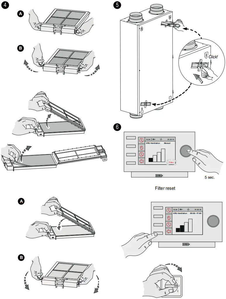
User maintenance is limited to periodically cleaning or replac-ing the filters. The filter only has to be cleaned when that is indicated on the display (it shows the text “FILTER”) or, if a multiple switch with filter indication is mounted, when the red LED at the switch lights up. The filters must be replaced every year.![]() It is not permitted to use the appliance without filters!
It is not permitted to use the appliance without filters! 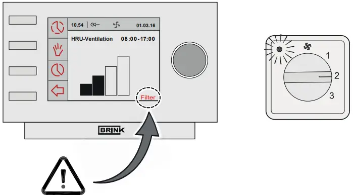
 8.2 Maintenance installer
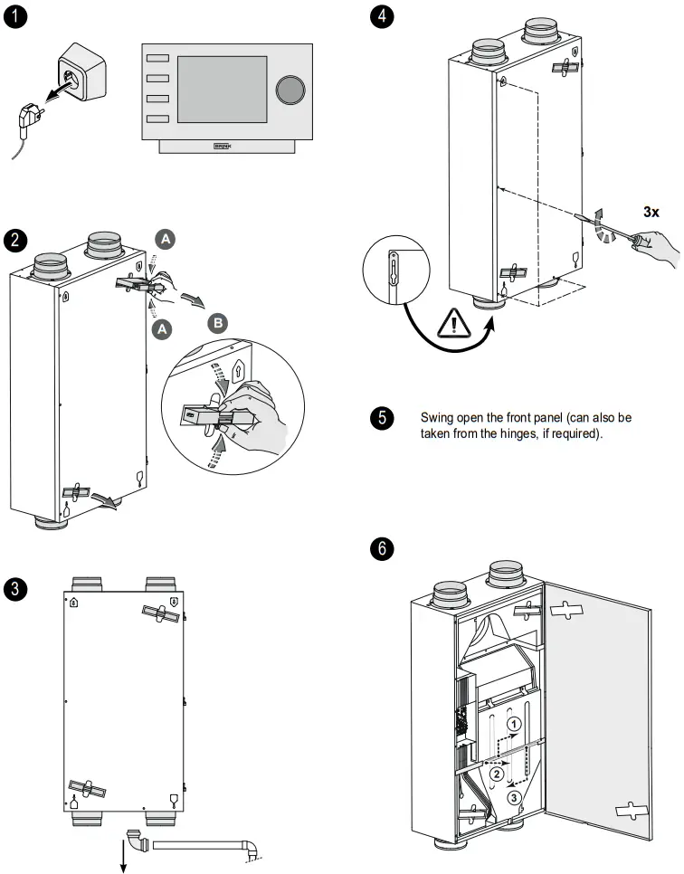
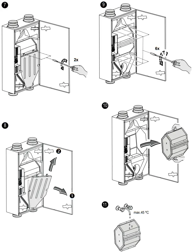
![]() Rinse the exchanger with hot water and a regular detergent.
Rinse the exchanger with hot water and a regular detergent.![]() For ceiling mounting, carefully remove the condensate bin; there may still be some condensate left in the condensate bin!
For ceiling mounting, carefully remove the condensate bin; there may still be some condensate left in the condensate bin!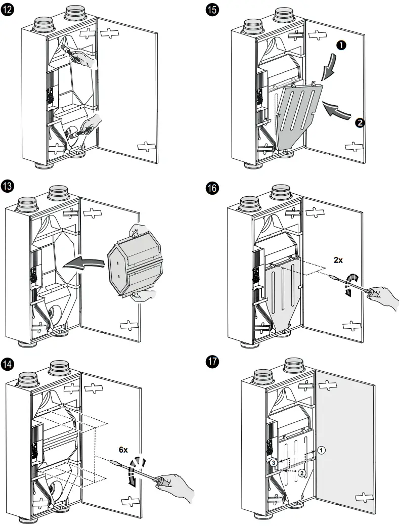
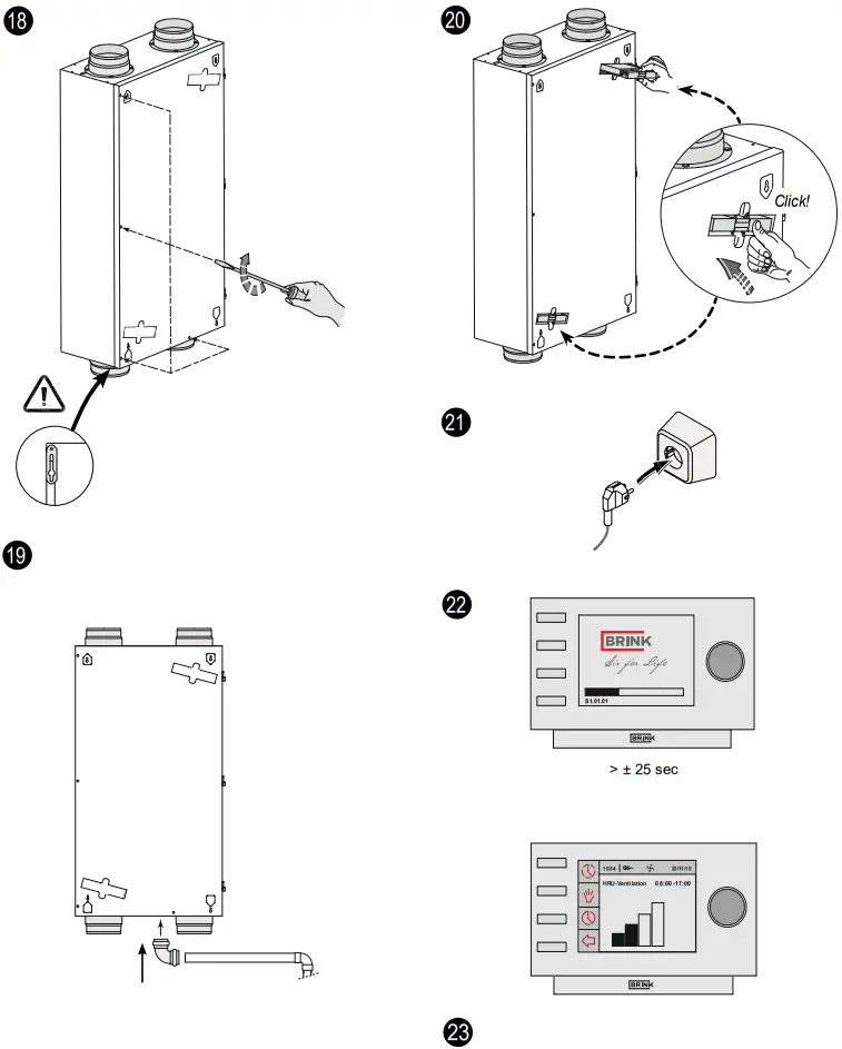 Filter reset; see §8.1 point 6
Press the Return key (![]() ) to leave any selected menu and the appliance will return to operating mode.
) to leave any selected menu and the appliance will return to operating mode.
Chapter 9 Electric connections
Wiring diagram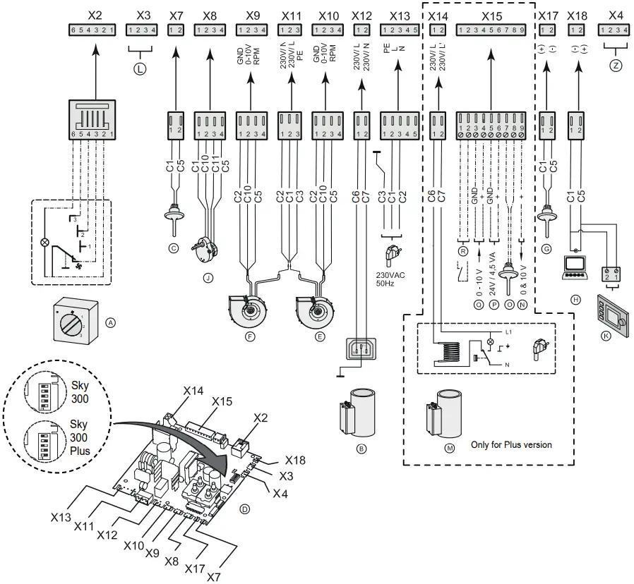
| C1 | C2 | C3 | C5 | C6 | C7 | C10 | C11 |
| brown | blue | green/ yellow | white | nr.1 | nr.2 | green | yellow |
| A | B | C | D | E | F | G | H | J |
| multiple switch | pre-heater | outdoor temperature sensor | control board | supply fan | extract fan | Indoor temperature sensor | service connector | Motor bypass valve |
| K | L | M | N | 0 | P | Q | R | Z |
| “Brink Air Control” | not applicable | post-heater | output 0-10V | sensor post-heater | 24V. | 0-10 V input | external switch contact | RH-sensor (optional) |
Chapter 10 Electric connections accessories
10.1 Connections connectors
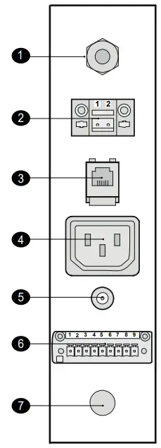
- Power plug 230V.
- EBus connector
- Modular connector for rpm control
- Connector for postheater
- Service connector
- Nine-pole screw connector (only for Plus version)
- Additional cable feed option
10.2 Connecting wireless remote control
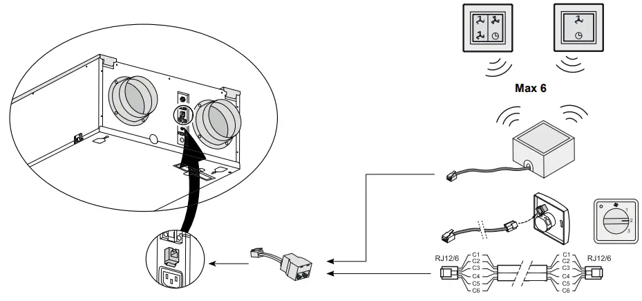
When several remote controls are used, the appliance will always run according to the remote control with the highest set ventilation mode.
The 4-way switch can also be used to activate a 30-minutes boost mode by putting the switch to setting 3 for less than 2 seconds and directly turning it back to setting 1 or 2. The boost mode can be reset by putting the switch to setting 3 for longer than 2 seconds or by switching it to absence mode (![]() ).
).
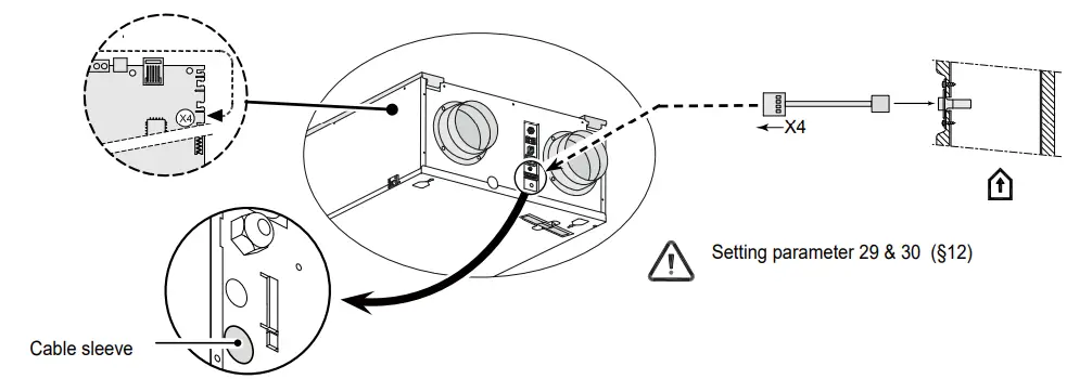
10.3 Connection RH (humidity)- sensor
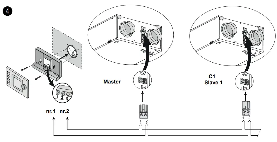
10.4 Coupling several Renovent Sky 300 appliances
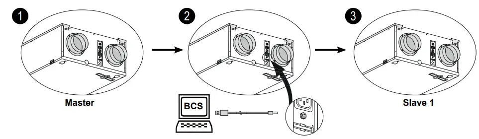
The slave appliances must be set as slaves before the appliances are interconnected through eBus! Refer to the supplied service tool manual for further instructions!
There must be a separate 230 volt wall socket for every appliance.
Because of polarity sensitivity, always connect contacts X1-1 to X1-1 and contacts X1-2 to X1-2. Never connect X1-1 and X1-2. Amaximum of 10 appliances (1 Master + 9 Slave max.)
10.5 Preheater connection
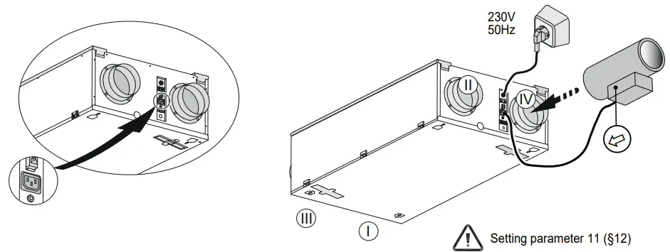
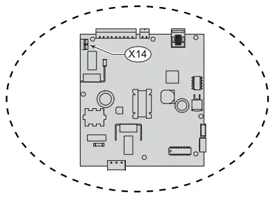
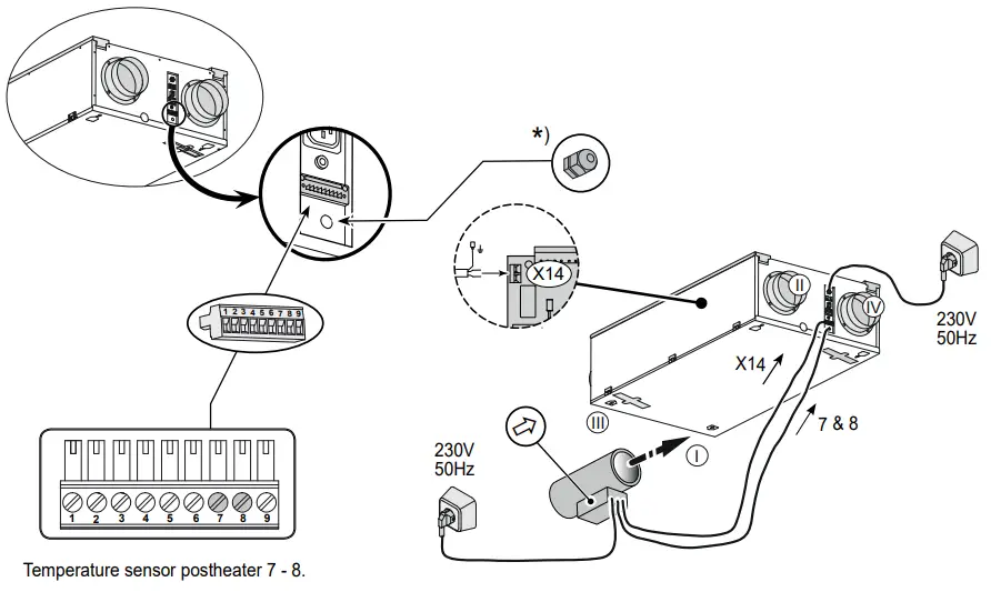
10.6 Connection postheater or extra preheater
The postheater or extra preheater (only possible for Renovent Sky Plus) are electrically connected to connector X14; just for a postheater there is also a temperature sensor that must be connected to no. 7 and 8 of the 9-pole connector that is only installed in the Plus version.
When using a postheater or extra preheater, step number 12 is applied (and for extra preheater also step number 13). Please refer to the mounting instructions that came with the heater for more extensive information regarding installation of the postheater or the extra preheater.
![]() Setting parameter 12 & 13 (§12)
Setting parameter 12 & 13 (§12)
The strain reliever to be installed by the *) installer (not supplied with the appliance:for feeding the 230 volt cable to the postheater or extra preheater.
10.7 Connection geo heat heat exchanger
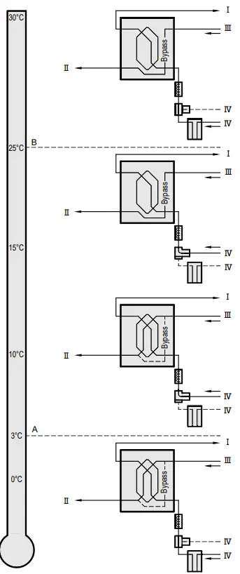
| A | Minimum temperature |
| B | Maximum temperature |
| Ⅰ | To dwelling |
| Ⅱ | To atmosphere |
| Ⅲ | From dwelling |
| Ⅳ | From atmosphere |
![]() Setting parameter 26, 27 & 28 (§12)
Setting parameter 26, 27 & 28 (§12)
10.8 Connecting external switch contact
An external switch contact (e.g. switch or relay contact) can be connected to the Renovent Sky Plus.
(f a second input is required as external switch contact, if necessary connections no. 3 and no. 4 can be reprogrammed.
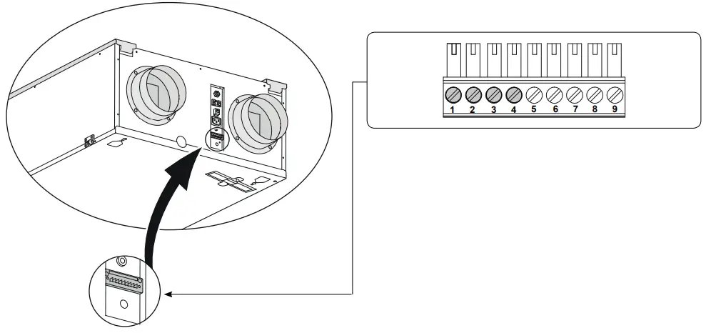
Connections no. 1 and no. 2 standard extemal switch contact; connections no. 3 and no. 4 can optionally be used as external switch contact as well.![]() Setting parameter 16, 17 & 18 (§ 12)
Setting parameter 16, 17 & 18 (§ 12)
10.9 Connection to 0-10 V input
The Renovent Sky Plus can be equipped with an external provision with 0-10 volt control.
Connections X15-3 and X15-4 are set as standard as 0 – 10 V input; it is activated as standard.
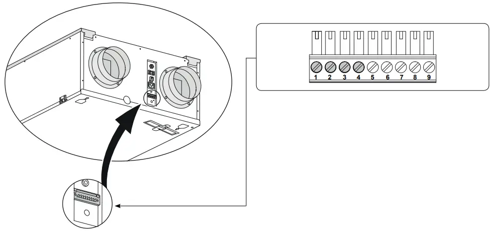
Connections no. 3 and no. 4 standard 0-10 volt input; connections no. 1 and no. 2 can optionally be used as 0-10 volt input as well.![]() Setting parameter 20, 21 & 22 (§12)
Setting parameter 20, 21 & 22 (§12)
Chapter 11 Service
11.1 Exploded view
When ordering parts, in addition to the article code number (see exploded view), please state the type of the heat recovery appliance, the serial number, the year of production and the name of the part:
N. B.:
Appliance type, serial number and year of production are state on the identification plate on the top of the appliance.
| Example | |
| Appliance type | Renovent Sky 300 |
| Serial number | 422004184301 |
| Year of production | 2018 |
| Part | Fan |
| Article code | 531774 |
| Qty | 1 |
Service Parts
| Nr. | Description | Code |
| 1 | Air duct connections (4 pcs) | 532004 |
| 2 | Fan (1 pcs) | 531774 |
| 3 | Temperature sensor NTC 10K (1 pcs) | 531775 |
| 4 | Heat exchanger | 532006 |
| 5 | Front cover with hinges | 532007 |
| 6 | Filter holder set (2 pieces) | 532005 |
| 7 | Filter kit 2x ISO Coarse 60% (G4) filter (standard version) | 532000 |
| 8 | Air Control | 510498 |
| 9 | Motor bypass valve | 531778 |
| 10 | Bypass valve | 531779 |
| 11 | Control board UWA-01 (Plus version) When replacing, note the correct dip switch settings. | 531780 |
| 12 | Cable with power plug 230 volt * | 531978 |
| 13 | Mounting strip | 530510 |
* The mains cable has a print connector.
When replacing it, always order a replacement mains cable Brink
To avoid dangerous situations, a damaged mains should only be replaced by a qualified person!
Modifications reserved
Brink Climate Systems B. V. continuously strives after improvement of products and reserves the right to change the specifications without prior notice.
Chapter 12 Setting values
| STEP NO. | DESCRIPTION | FACTORY SETTING RENOVENT SKY | ADJUSTING RANGE | STEP |
| 1 | Air flow rate mode | 50 m3/h | 0 m³/h or 50 m³/h | |
| 2 | Air flow rate mode 1 / | 100 m³/h | 50 m³/h – 300 m³/h | 5 m³/h |
| 3 | Air flow rate mode 2 / | 150 m³/h | 50 m³/h – 300 m³/h | 5 m³/h |
| 4 | Air flow rate mode 3 / | 225 m³/h | 50 m³/h – 300 m³/h | 5 m³/h |
| 5 | Bypass temperature | 22,0 °C | 15,0 °C – 35,0 °C | 0,5 °C |
| 6 | Bypass hysterese | 2,0 °C | 0,0 °C – 5,0 °C | 0,5 °C |
| 7 | Operation bypass valve | 0 | 0 (= Automatic) 1 (= Bypass valve closed) 2 (= Bypass valve open) | |
| 8 | Central heating + heat recovery | OFF | OFF (=Central heating+heat recovery off) ON (= Central heating+heat recovery on) | |
| 9 | Imbalance permissible | ON | OFF (= flow rate supply equals extract) ON (= imbalance permissible) | |
| 10 | Fixed imbalance | 0 m³/h | -100 m³/h t/m 100 m³/h | 1 m³/h |
| 11 | Preheater connected | OFF | ON (= preheater connected) OFF (= no preheater) | |
| STEP NO. | DESCRIPTION | FACTORY SETTING RENOVENT SKY PLUS | ADJUSTING RANGE | STEP |
| 12 | Heater | 0 | 0 (= no additional heater) 1 (= additional preheater) 2 (= postheater) | |
| 13 | Temperature postheater | 21,0 °C | 15,0 °C – 30,0 °C | 0,5 °C |
| 14 | Selection input 1 | 0 | 0 (= normally open contact) 1 (= 0 – 10V input active) 2 (= normally closed contact) 3 (= input 1/ bypas open ⇒ 12V; bypass closed ⇒ 0V) 4 (= input 1/ bypas open ⇒ 0V; bypass closed ⇒ 12V) | |
| 15 | Minimum voltage input 1 | 0,0 V | 0 Volt – 10 Volt | 0,5 V |
| 16 | Maximum voltage input 1 | 10,0 V | 0 Volt -10 Volt | 0,5 V |
| 17 | Conditions switching input 1 | 0 1 (on) | 0 (off) 2 (= On if conditions bypass open satisfied) 3 (= Bypass control) 4 (= Bedroom valve) | |
| 18 | Supply fan mode switching input 1 | 5 | 0 (= Input fan off) 1 (= Absolute min. flow rate 50 ma/h) 2 (= Flow rate mode 1 ) 3 (= Flow rate mode 2) 4 (= Flow rate mode 3) 5 (= Multiple switch 6 (= Maximum flow rate) 7 (= No input fan activation) |
| STEP NO. | DESCRIPTION | FACTORY SETTING RENOVENT SKY PLUS | ADJUSTING RANGE | STEP |
| 19 | Extract fan mode switching input 1 | 5 | 0 (= Extract fan off) 1 (= Absolute min. flow rate 50 m³/h) 2 (= Flow rate mode 1) 3 (= Flow rate mode 2) 4 (= Flow rate mode 3) 5 (= Multiple switch) 6 (= Maximum flow rate) 7 (= No extract fan activation) | |
| 20 | Selection input 2 | 1 | 0 (= normally open contact) 1 (= 0 – 10V input active) 2 (= normally closed contact) 3 (= input 2/ bypas open ⇒12V; bypass closed ⇒0V) 4 (= input 2/ bypas open ⇒0V; bypass closed ⇒12V) | |
| 21 | Minimum voltage input 2 | 0,0 V | 0,0 Volt – 10,0 Volt | 0,5 V |
| 22 | Maximum voltage input 2 | 10,0 V | 0,0 Volt- 10,0 Volt | 0,5 V |
| 23 | Conditions switching input 2 | 0 | 0 (off) 1 (on) 2 (= On if conditions bypass open satisfied) 3 (= Bypass control) 4 (= Bedroom valve) | |
| 24 | Supply fan mode switching input 2 | 5 | 0 (= Input fan off) 1 (= Absolute min. flow rate 50 m³/h) 2 (= Flow rate mode 1) 3 (= Flow rate mode 2) 4 (= Flow rate mode 3) 5 (= Multiple switch) 6 (= Maximum flow rate) 7 (= No input fan activation) | |
| 25 | Extract fan mode switching input 2 | 5 | 0 (= Extract fan off) 1 (= Absolute min. flow rate 50 m³/h) 2 (= Flow rate mode 1) 3 (= Flow rate mode 2) 4 (= Flow rate mode 3) 5 (= Multiple switch) 6 (= Maximum flow rate) 7 (= No extract fan activation) | |
| 26 | Geo heat exchanger | OFF | OFF (= Valve control geo heat exchanger off) ON (= Valve control geo heat exchanger on) | |
| 27 | Minimum temperature geo heat exchanger (Below this temperature the valve opens.) | 5,0 °C | 0,0 °C – 10,0 °C | 0,5 °C |
| 28 | Maximum temperature geo heat exchanger (Above this temperature the valve opens.) | 25,0 °C | 15,0 °C – 40,0 °C | 0,5 °C |
| STEP NO. | DESCRIPTION | FACTORY SE TTINKYG RENOVENT SKY | ADJUSTING RANGE | STEP |
| 29 | RH-sensor | OFF | OFF (= RH-sensor not active) ON (= RH-sensor active) | |
| 30 | Sensitivity RH-sensor | 0 | +2 most sensitive +1 ↑ 0 default setting RH-sensor -1 ↓ -2 least sensitive |
| STEP NO. | DESCRIPTION | FACTORY SETTING RENOVENT SKY PLUS | ADJUSTING RANGE | STEP |
| 35 | Switching on and off eBus CO2 sensor | OFF | ON – OFF | – |
| 36 | Min. PPM eBus CO₂-sensor 1 | 400 1200 | 400-2000 | 25 |
| 37 | Max. PPM eBus CO₂-sensor 1 | |||
| 38 | Min. PPM eBus CO₂-sensor 2 | 400 | ||
| 39 | Max. PPM eBus CO₂-sensor 2 | 1200 | ||
| 40 | Min. PPM eBus CO₂-sensor 3 | 400 | ||
| 41 | Max. PPM eBus CO₂-sensor 3 | 1200 | ||
| 42 | Min. PPM eBus CO₂-sensor 4 | 400 | ||
| 43 | Max. PPM eBus CO₂-sensor 4 | 1200 | ||
| 4 | Flow correction | 100% | 90% – 110% | % |
| 45 | Default position switch 1 | 0 – 1 | – | |
| STEP NO. | DESCRIPTION | FACTORY SETTING RENO- VENT SKY | ADJUSTING RANGE | STEP |
| 46 | Brink Connect | 1 | 1 Brink Connect function (external, Brink connect no RH sensor) 3 Brink Connect (internal) |
Chapter 13 ERP-values
| Productdatasheet conform Ecodesign (EU), nr. 1254/2014 (Annex IV) | |||||
| Supplier: | Brink Climate Systems B.V. | ||||
| Model: | Renovent Sky 300 (Plus) | ||||
| Climate zone | Type of control | SEC-Value in kWh/m2/a | Energyclass (SEC) | The annual electricity consumption (AEC) in kWh | The annual heating saved (AHS) in kWh |
| Average | “Brink Air Control” | -36,99 | A | 328 | 4365 |
| Central demand control | -38,84 | A | 298 | 4415 | |
| Local demand control | -42,09 | A+ | 239 | 4516 | |
| Cold | “Brink Air Control” | -79,22 | Ai- | 865 | 8539 |
| Central demand control | -81,56 | A+ | 835 | 8637 | |
| Local demand control | -85,79 | A+ | 776 | 8835 | |
| Warm | “Brink Air Control” | -12,79 | E | 283 | 1974 |
| Central demand control | -14,37 | E | 253 | 1997 | |
| Local demand control | -17,06 | E | 194 | 2042 | |
| Type of ventilation unit: | Ventilation unit with heat recovery | ||||
| Fan: | Variable speed EC fan | ||||
| Type of heat exchanger: | Recuperative plastic cross-counterflow heatexchanger | ||||
| Thermal efficiency: | 84% | ||||
| Maximum flow rate: | 300 m³/h | ||||
| Electric power input: | 116 W | ||||
| Sound power level Lwa: | 44 dB(A) | ||||
| Reference flow rate : | 210 m³/h | ||||
| Reference pressure difference: | 50Pa | ||||
| Specific Power Input (SEL): | 0,24 W/m³/h | ||||
| Control factor: | 1,0 in combination with manual switch | ||||
| 0,95 in combination with “Brink Air Control” | |||||
| 0,85 in combination with central demand control withl sensor | |||||
| 0,65 in combination with local demand control with at least two or more sensors and with at least a two-zone control | |||||
| Leakage*: | Internal | 0,9% | |||
| External | 2,0% | ||||
| Filterwaming: | On the Manual switch / “Brink Air Control” Attention! For optimal energy efficiency and a proper operation a regular filter inspection, cleaning or replacement is necessary. | ||||
| Internet address for Assembly instructions: | http://www.brinkdimatesystems.nl/installateurs/kenniscentrum/Documentatie.aspx | ||||
| Bypass: | Yes; 100% Bypass | ||||
* Measurements executed by TNO according to the EN 13141-7 standard (TNO-report TNO 2012M10384A, July 2012)
| Classification from 1 January 2016 | |
| SEC Class “Average climate”) | SEC in kWh/m²/a |
| A+ (Most efficient) | SEC < -42 |
| A | -42 ≤ SEC < -34 |
| B | -34 ≤ SEC < -26 |
| C | -26 ≤ SEC < -23 |
| D | -23 ≤ SEC < -20 |
| E (Least efficient) | -20 ≤ SEC < -10 |
DECLARATION OF CONFORMITY
Manufacturers: Brink Climate Systems B.V.
Address:
P.O. Box 11
NL-7950 AA Staphorst,
The Netherlands
Product :
Renovent Sky 300
Renovent Sky 300 plus
The product described above complies with following directives:
♦ 2014/35/EU (low voltage directive)
♦ 2014/30/EU (EMC directive)
♦ RoHS 2011/65/EU (substances directive)
♦ 2009/125/EG (1253/1254 EU (EU ErP- directive))
The product bears the CE label: ![]()
Staphorst, 05-01-12
W. Hijmissen,
Managing director
WWW.BRINKAIRFORLIFE.NL
![]() BRINK CLIMATE SYSTEMS B.V.
BRINK CLIMATE SYSTEMS B.V.
P.O. Box 11 NL-7950 AA Staphorst The Netherlands
Wethouder Wassebaliestraat 8 7951SN Staphorst The Netherlands
T. +31 (0) 522 46 99 44
F. +31 (0) 522 46 94 00
[email protected]
www.brinkclimatesystems.nl
612378-G Octobor 2018
 Mechanical Ventilation With Heat Recovery Instruction Manual")


