Altronix T1PHK1F4S 4 Door Kit with Fused Outputs
Access & Power Integration
T1PHK1F4S
4 Door Kit with Fused Outputs
Fully assembled kit includes:
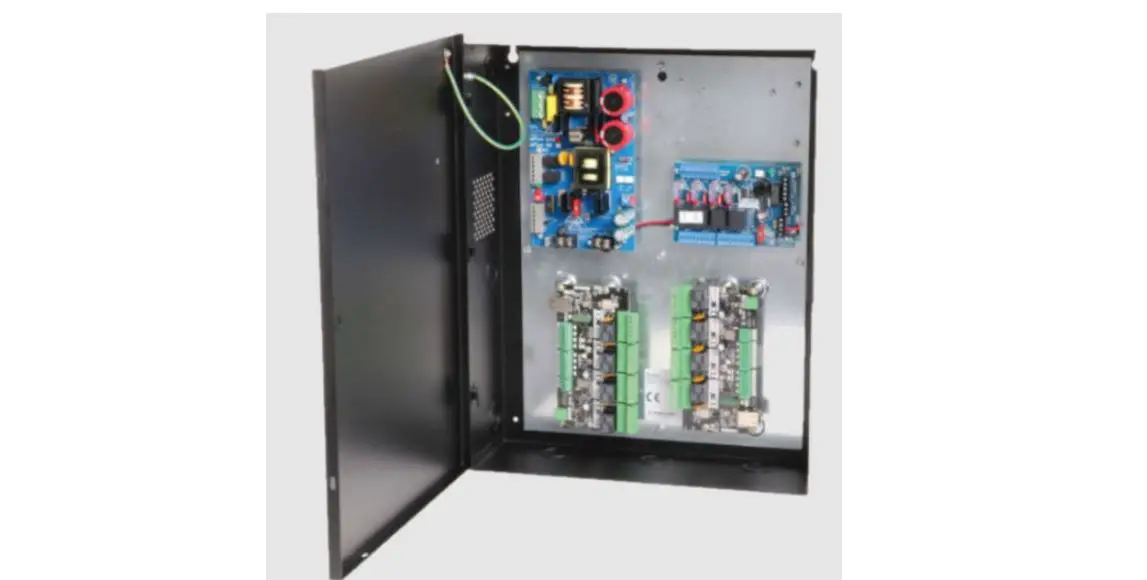
- Trove1 enclosure with TC1 Altronix/Open path backplane
- One (1) eFlow4NB – Power Supply/Charger
- One (1) ACM4 – Fused Access Power Controller
- One (1) VR6 – Voltage Regulator
- One (1) PDS8 – Dual Input/ Output Fused Power Distribution Module
T1PHK3F8
8 Door Kit with Fused Outputs
Fully assembled kit includes:
- Trove1 enclosure with TC1 Altronix/Open path backplane
- One (1) eFlow6NB – Power Supply/Charger
- One (1) ACM8 – Fused Access Control Module
T2PHK33F16
16 Door Kit with Fused Outputs
Fully assembled kit includes:
- Trove2 enclosure with TCV2 Altronix/Open path backplane
- Two (2) eFlow6NB – Power Supply/Chargers
- Two (2) ACM8 – Fused Access Control Modules
T2PHK77F24
24 Door Kit with Fused Outputs
Fully assembled kit includes:
- Trove2 enclosure with TCV2 Altronix/Open path backplane
- Two (2) eFlow104NB – Power Supply/Chargers
- Three (3) ACM8 – Fused Access Control Modules
T1PHK1F4SD
4 Door Kit with PTC Outputs
Fully assembled kit includes:
- Trove1 enclosure with TC1 Altronix/Open path backplane
- One (1) eFlow4NB – Power Supply/Charger
- One (1) ACM4CB – PTC Access Power Controller
- One (1) VR6 – Voltage Regulator
- One (1) PDS8CB – Dual Input/ Output PTC Power Distribution Module
T1PHK3F8D
8 Door Kit with PTC Outputs
Fully assembled kit includes:
- Trove1 enclosure with TC1 Altronix/Open path backplane
- One (1) eFlow6NB – Power Supply/Charger
- One (1) ACM8CB – PTC Access Control Module
T2PHK33F16D
16 Door Kit with PTC Outputs
Fully assembled kit includes:
- Trove2 enclosure with TCV2 Altronix/Open path backplane
- Two (2) eFlow6NB – Power Supply/Chargers
- Two (2) ACM8CB – PTC Access Control Modules
T2PHK77F24D
24 Door Kit with PTC Outputs
Fully assembled kit includes:
- Trove2 enclosure with TCV2 Altronix/Open path backplane
- Two (2) eFlow104NB – Power Supply/Chargers
- Three (3) ACM8CB – PTC Access Control Modules
All components of these Trove kits are UL Listed sub-assemblies. Please refer to the included corresponding Sub-Assembly Installation Guides for further information.
Installation Guide
All registered trademarks are property of their respective owners.
Rev. TPHK_080921
Installing Company: _________________________ Service Rep. Name: __________________________________________
Address: _________________________________________________________ Phone #: _________________________
Overview:
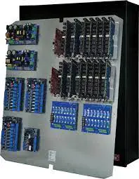
Altronix Trove Open path kits are pre-assembled and consist of Trove enclosures/backplanes with factory installed Altronix power supply/chargers and sub-assemblies. These kits also accommodate various combinations of Open path boards for up to twenty four (24) doors in a single enclosure.
Configuration Chart:
|
Altronix Model Number | Power Supply Board Input Fuse Rating | Power Supply Board Battery Fuse Rating | 120VAC 60Hz Input Current (A) | Maximum Supply Current for Main and Aux. Outputs on Power Supply board, ACM4(CB)/ ACM8(CB) Access Power Controllers’ or PDS8(CB) outputs | Nominal DC Output Voltage | Fail-Safe/Fail-Secure or Dry Form “C” Outputs | Additional Fuse or PTC Protected Outputs | ACM4/ACM4CB Board Input Fuse Rating | ACM4 Board Output Fuse Rating | ACM4CB Board Output PTC Rating | ACM8(CB) Board Input Fuse Rating | ACM8 Board Output Fuse Rating | ACM8CB Board Output PTC Rating | PDS8 Board Input Fuse Rating | PDS8 Board Output Fuse Rating | PDS8CB Board Input PTC Rating | PDS8 Board Output PTC Rating | |
| Power Supply | ||||||||||||||||||
| [DC] | [Aux] | |||||||||||||||||
| Output Range (VDC) | Output Range (VDC) | |||||||||||||||||
| T1PHK1F4S |
5A/ 250V |
15A/ 32V | 3.5 | 24VDC @ 3.7A | 20.17-26.4 | 20.28-26.4 | 4 | 8 | 10A/32V | 3A/ 32V | – | – | – | – | 10A/ 32V | 3A/ 32V | – | – |
| T1PHK1F4SD | – | 2.5A | – | – | 9A | 2.5A | ||||||||||||
| T1PHK3F8 | 3.5 | 24VDC @ | 20.17- 26.4 | 20.28- 26.4 | 8 | – | – | – | – | 10A/ 250V | 2.5A/ 250V | – |
– |
– |
– |
– | ||
| T1PHK3F8D | – | 2.5A | ||||||||||||||||
| T2PHK33F16 | 7.0 | 24VDC @ 5.9A | 20.17-26.4 | 20.28-26.4 | 16 | – | 2.5A/ 250V | – | ||||||||||
| T2PHK33F16D | – | 2.5A | ||||||||||||||||
| T2PHK77F24 | 6.3A/ 250V | 15A/ | 9.0 | 24VDC @ 9.7A + 24VDC @9.7A | 20.17-26.4 | 20.28-26.4 | 24 | – | – | – | – | 10A/ 250V | 2.5A/ 250V | – | – | – | – | – |
| T2PHK77F24D | – | 2.5A | ||||||||||||||||
Installation Instructions:
Wiring methods shall be in accordance with the National Electrical Code/NFPA 70/ANSI, and with all local codes and authorities having jurisdiction. Product is intended for indoor use only.
- Remove backplane from enclosure. Do not discard hardware.
- Mark and predrill holes in the wall to line up with the top three keyholes in the enclosure. Install two/three upper fasteners and screws in the wall with the screw heads protruding. Place the enclosure’s upper keyholes over the two/three upper screws; level and secure. Mark the position of the lower two/three holes. Remove the enclosure. Drill the lower holes and install the fasteners. Place the enclosure’s upper keyholes over the upper screws. Install the lower screws and make sure to tighten all screws.
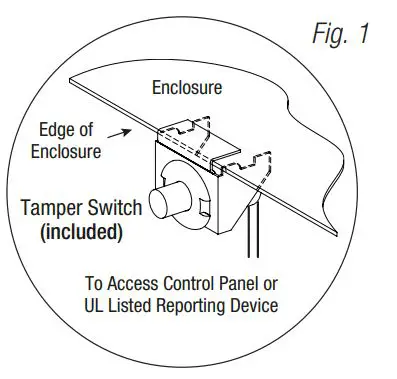
- Mount included UL Listed tamper switch(as) (Altronix Model TS112 or equivalent) in desired location, opposite hinge. Slide the tamper switch bracket onto the edge of the enclosure approximately 2” from the right side (Fig. 1, pg. 2). Connect tamper switch wiring to the Access Control Panel input or the appropriate UL Listed reporting device. To activate alarm signal open the door of the enclosure.
- Mount Open path boards to backplane, refer to pages 3-6.
- Refer to the fellow Power Supply/Charger Installation Guide (eFlow4NB, eFlow6NB, eFlow104NB) and corresponding Sub-Assembly Installation Guide (ACM4(CB), ACM8(CB), PDS8(CB) and VR6) for further installation instructions.
T1PHK1F4S(D): Configuration of Open path Boards
- Mount appropriate Open path boards into the correct positions by positioning pre-mounted spacers over appropriate holes on the backplane and depressing down on board to secure spacer to the backplane (Fig. 2, pg. 3).
- Fasten TC1 backplane to Trove1 enclosure utilizing pan head screws (provided).
Access Controller Position Chart for the Following Open path Modules:
| Open path | Mounting Position |
| OP-ACC | A |
| OP-EX-4E | B |
| OP-EX-8E | C |
| OP-16EM | D |

T1PHK3F8(D): Configuration of Open path Boards
- Mount appropriate Open path boards into the correct positions by positioning pre-mounted spacers over appropriate holes on the backplane and depressing down on board to secure spacer to the backplane (Fig. 3, pg. 4).
- Fasten TC1 backplane to Trove1 enclosure utilizing pan head screws (provided).
Access Controller Position Chart for the Following Open path Modules:
| Open path | Mounting Position |
| OP-ACC | A |
| OP-EX-4E | B |
| OP-EX-8E | C |
| OP-16EM | D |
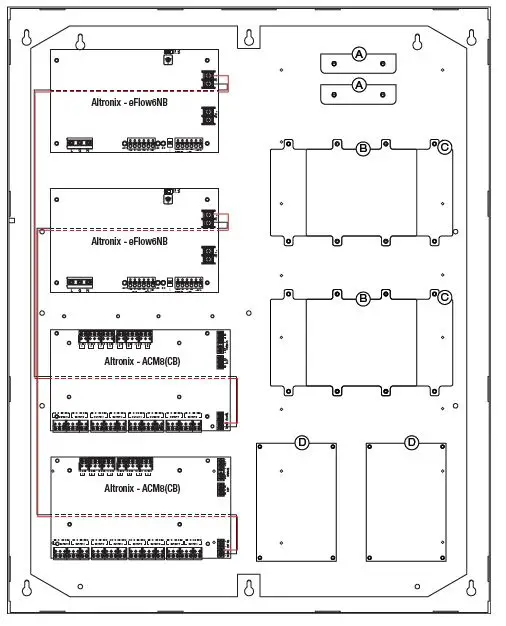
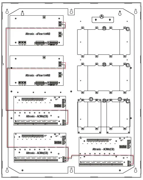
T2PHK33F16(D): Configuration of Open path Boards
- Mount appropriate Open path boards into the correct positions by positioning pre-mounted spacers over appropriate holes on the backplane and depressing down on board to secure spacer to the backplane (Fig. 4, pg. 5).
- Fasten TC2 backplane to Trove2 enclosure utilizing pan head screws (provided).
Access Controller Position Chart for the Following Open path Modules:
| Open path | Mounting Position |
| OP-ACC | A |
| OP-EX-4E | B |
| OP-EX-8E | C |
| OP-16EM | D |
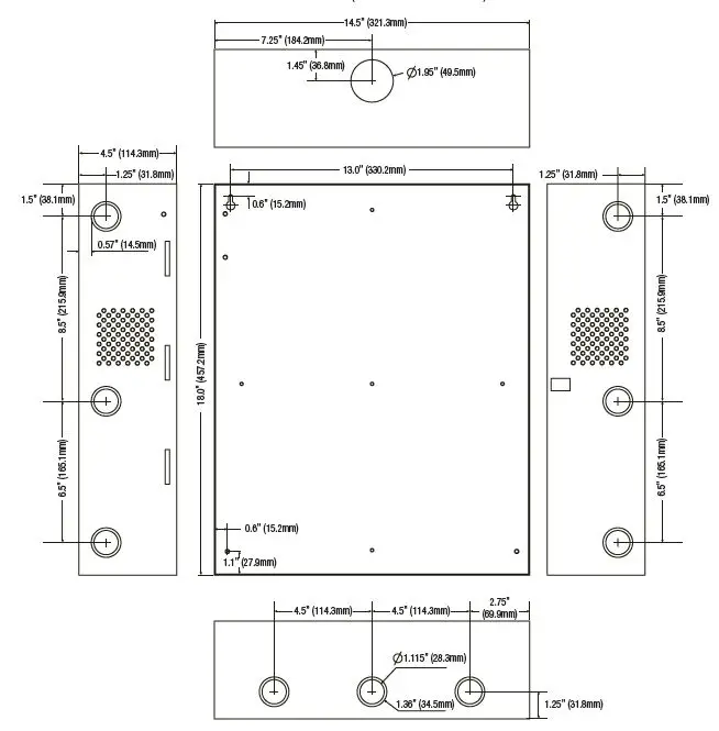
T1PHK1F4S(D) and T1PHK3F8(D) (Trove1) Enclosure Dimensions (H x W x D approximate):
18” x 14.5” x 4.625” (457mm x 368mm x 118mm)
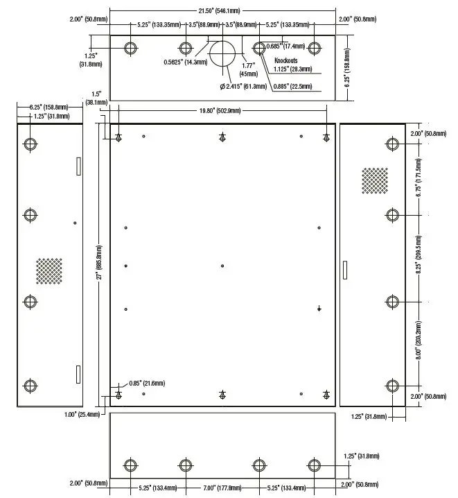
T2PHK33F16(D) and T2PHK77F24(D) (Trove2) Enclosure Dimensions (H x W x D approximate):
27.25” x 21.5” x 6.5” (692.2mm x 552.5mm x 165.1mm)
Altronix is not responsible for any typographical errors.140 58th Street, Brooklyn, New York 11220 USA
phone: 718-567-8181
fax: 718-567-9056
website: www.altronix.com
e-mail: [email protected]
Lifetime Warranty
II Trove Open path Kits H09U


