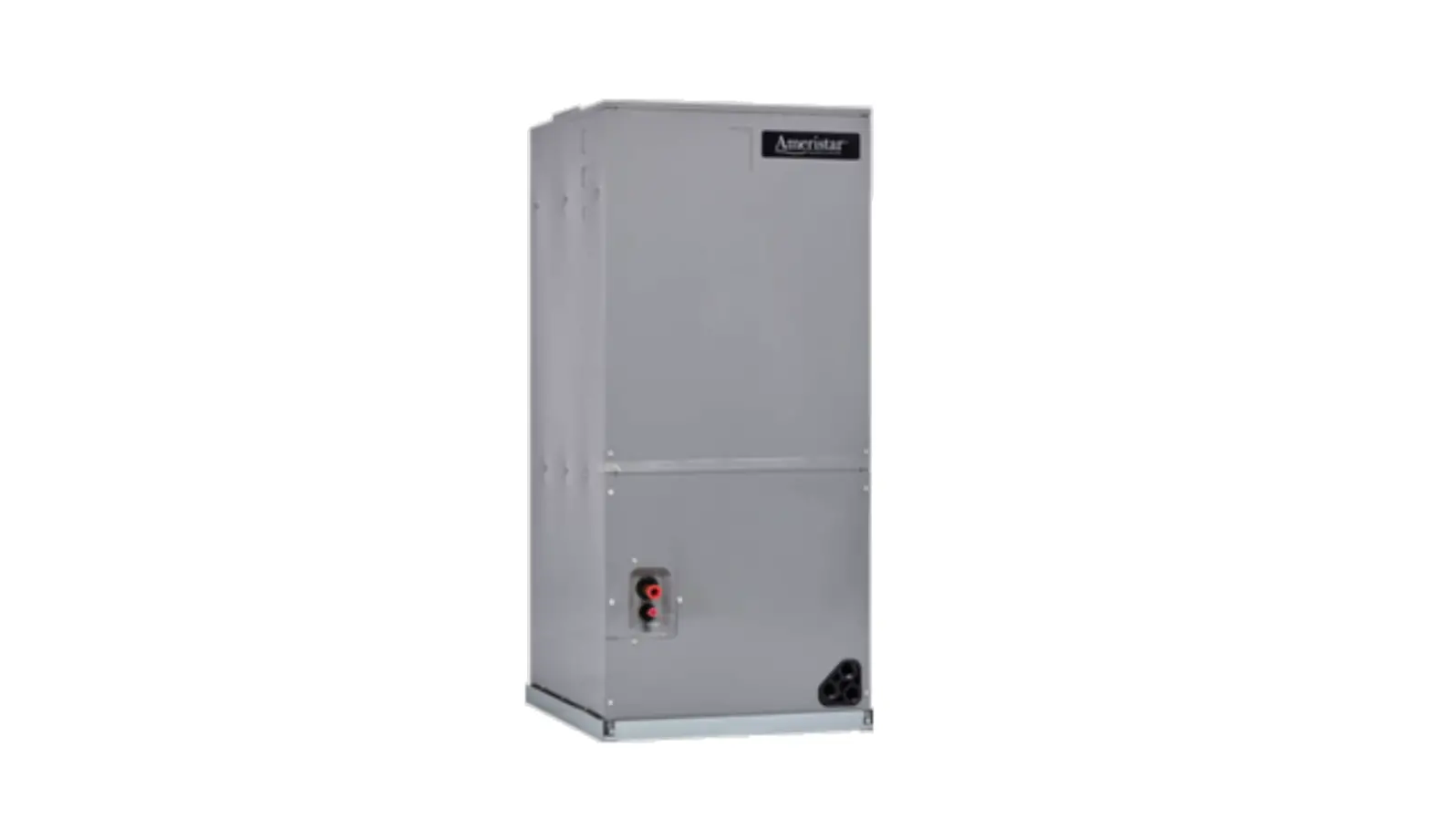
AMERISTAR A4AH4E60A1C30C 5.0 Ton Convertible Air Handler User Manual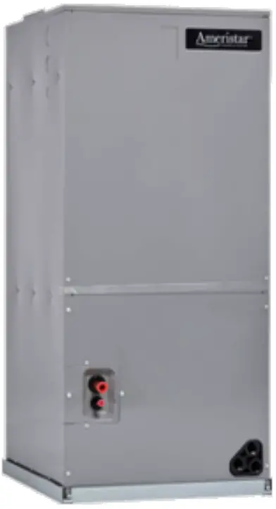
Outline Drawing
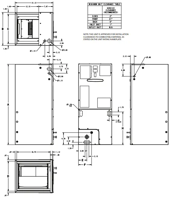
| PRODUCT DIMENSIONS | |||||||||
| Air Handler Model | A | B | C | D | E | F | H | Flow Control | Gas Line Braze |
| A4AH4E60 | 51.27 | 23.50 | 21.50 | 21.75 | 7.01 | 9.66 | 24.59 | TXV | 7/8 |
| All dimensions are in inches | |||||||||
Product Specifications
| MODEL | A4AH4E60A1C30C |
| RATED VOLTS/PH/HZ | 208-230/1/60 |
| RATINGS(a) | See O.D. Specifications |
| INDOOR COIL — Type | Plate Fin |
| Rows — F.P.I. | 4 – 14 |
| Face Area (sq. ft.) | 5.91 |
| Tube Size (in.) | 3/8 |
| Refrigerant Control | TXV |
| Drain Conn. Size (in.)(b) | 3/4 NPT |
| DUCT CONNECTIONS | See Outline Drawing |
| INDOOR FAN — Type | Centrifugal |
| Diameter-Width (In.) | 11 X 8 |
| No. Used | 1 |
| Drive – No. Speeds | Direct – 3 (c) |
| CFM vs. in. w.g. | See Fan Performance Table |
| No. Motors — H.P. | 1 – 3/4 |
| Motor Speed R.P.M. | 1050 |
| Volts/Ph/Hz | 208-230/1/60 |
| F.L. Amps | 6.3 |
| FILTER | |
| Filter Furnished? (d) | No |
| REFRIGERANT | R-410A |
| Ref. Line Connections | Brazed |
| Coupling or Conn. Size — in. Gas | 7/8 |
| Coupling or Conn. Size — in. Liq. | 3/8 |
| DIMENSIONS | H x W x D |
| Crated (In.) | 52–1/2 x 26 x 24 |
| Uncrated | 51-3/8 x 23-1/2 x 21-1/8 |
| WEIGHT | |
| Shipping (Lbs.) / Net (Lbs.) | 145/138 |
- These Air Handlers are A.H.R.I certified with various Split System Air Conditioners and Heat Pumps (AHRI STANDARD 210/240). Refer to the Split System Outdoor Unit Product Data Guides for performance data.
- 3/4” Male Plastic Pipe (Ref: ASTM 1785–76)
- ECM Motor
- Remote filter required.
Minimum Airflow CFM
| A4AH4E60A1C30C | ||
| Heater | Minimum Heat Speed Tap | |
| With Heat Pump | Without Heat Pump | |
| BAYHTR1504BRK, BAYHTR1504LUG, BAYHTR1505BRK, BAYHTR1505LUG | Low | Low |
| BAYHTR1508BRK, BAYHTR1508LUG, BAYHTR1510BRK, BAYHTR1510LUG, BAYHTR3510LUG | Low | Low |
| BAYHTR1517BRK | Low | Low |
| BAYHTR1523BRK | Med-Low | Med-Low |
| BAYHTR1525BRK | Med | Med-Low |
| BAYHTR3517LUG | Low | Low |
| Low = Taps 1–3 | ||
Fixed Orifice Superheat Charging Table
| Indoor Wet Bulb Temp (F) | ||||||||||||||||||||||||||||||
| Outdoor Dry Bulb Temperature (F) | 50 | 51 | 52 | 53 | 54 | 55 | 56 | 57 | 58 | 59 | 60 | 61 | 62 | 63 | 64 | 65 | 66 | 67 | 68 | 69 | 70 | 71 | 72 | 73 | 74 | 75 | 76 | 77 | 78 | |
| 55 | 7 | 9 | 10 | 11 | 12 | 14 | 15 | 17 | 18 | 20 | 21 | 23 | 24 | 26 | 27 | 29 | 30 | |||||||||||||
| 60 | 5 | 7 | 8 | 9 | 10 | 12 | 13 | 15 | 16 | 18 | 19 | 21 | 22 | 24 | 25 | 27 | 28 | 30 | 31 | |||||||||||
| 65 | 4 | 6 | 8 | 10 | 11 | 13 | 14 | 16 | 17 | 18 | 19 | 21 | 22 | 24 | 25 | 27 | 28 | 27 | 31 | |||||||||||
| 70 | 5 | 7 | 8 | 10 | 11 | 13 | 14 | 16 | 17 | 18 | 19 | 21 | 22 | 24 | 25 | 27 | 28 | 30 | 31 | |||||||||||
| 75 | 5 | 6 | 7 | 9 | 10 | 12 | 14 | 16 | 18 | 19 | 21 | 22 | 24 | 26 | 28 | 29 | 31 | 32 | ||||||||||||
| 80 | 4 | 6 | 7 | 9 | 10 | 11 | 12 | 14 | 16 | 18 | 19 | 21 | 23 | 25 | 26 | 28 | 29 | 31 | 33 | |||||||||||
| 85 | 4 | 6 | 7 | 9 | 10 | 13 | 14 | 16 | 18 | 20 | 21 | 23 | 24 | 26 | 28 | 29 | 30 | 31 | 32 | |||||||||||
| 90 | 4 | 6 | 8 | 10 | 11 | 13 | 14 | 16 | 18 | 20 | 22 | 24 | 25 | 27 | 28 | 30 | 31 | |||||||||||||
| 95 | 4 | 6 | 8 | 10 | 13 | 14 | 16 | 18 | 20 | 22 | 23 | 25 | 26 | 28 | 29 | |||||||||||||||
| 100 | 6 | 8 | 10 | 12 | 13 | 16 | 18 | 20 | 21 | 23 | 25 | 27 | 29 | |||||||||||||||||
| 105 | 4 | 6 | 7 | 9 | 11 | 13 | 15 | 18 | 20 | 22 | 24 | 26 | 28 | |||||||||||||||||
| 110 | 4 | 7 | 9 | 11 | 13 | 16 | 18 | 21 | 23 | 26 | 28 | |||||||||||||||||||
| 115 | 6 | 9 | 12 | 14 | 16 | 19 | 21 | 24 | 26 | |||||||||||||||||||||
| Using a digital psychrometer, measure the return air wet-bulb temperature at the unit just before the coil. Also measure the outdoor dry-bulb temperature. Use these temperatures to locate the target superheat on the charging table. Do not attempt to charge the system if these conditions fall outside of this charging table. ADD refrigerant to DECREASE total superheat. REMOVE refrigerant to INCREASE total superheat. Always allow 10 to 15 minutes of operation after any refrigerant or air flow change prior to determining the final superheat. | ||||||||||||||||||||||||||||||
Heater Pressure Drop Table
A4AH4 Air Handler Models
| Airflow CFM | Number of Racks | Heater Racks | ||||
| 1 | 2 | 3 | 4 | Heater Model | No. of Racks | |
| Air Pressure Drop — Inches W.G. | BAYHTR1504 | 1 | ||||
| 1800 | 0.02 | 0.04 | 0.06 | 0.14 | BAYHTR1505 | 1 |
| 1700 | 0.02 | 0.04 | 0.06 | 0.14 | BAYHTR1508 | 2 |
| 1600 | 0.02 | 0.04 | 0.06 | 0.13 | BAYHTR1510 | 2 |
| 1500 | 0.02 | 0.04 | 0.06 | 0.12 | BAYHTR3510 | 3 |
| 1400 | 0.02 | 0.04 | 0.06 | 0.12 | BAYHTR1517 | 3 |
| 1300 | 0.02 | 0.04 | 0.05 | 0.11 | BAYHTR3517 | 3 |
| 1200 | 0.01 | 0.04 | 0.05 | 0.10 | BAYHTR1523 | 4 |
| 1100 | 0.01 | 0.03 | 0.05 | 0.09 | BAYHTR1525 | 4 |
| 1000 | 0.01 | 0.03 | 0.04 | 0.09 | ||
| 900 | 0.01 | 0.03 | 0.04 | 0.08 | ||
| 800 | 0.01 | 0.03 | ||||
| 700 | 0.01 | 0.02 | ||||
| 600 | 0.01 | 0.02 | ||||
Performance and Electrical Data
- See Product Data or Air Handler nameplate for approved combinations of Air Handlers and Heaters.
- Heater model numbers may have additional suffix digits.
Table 1. Air Flow Performance
| A4AH4E60A1C30C | |||
| EXTERNAL STATIC (in w.g) | AIRFLOW | ||
| Speed Taps — 208 – 230 VOLTS | |||
| High | Med † | Low | |
| 0.1 | 1836 | 1744 | 1665 |
| 0.2 | 1790 | 1698 | 1612 |
| 0.3 | 1743 | 1650 | 1560 |
| 0.4 | 1694 | 1601 | 1509 |
| 0.5 | 1644 | 1550 | 1457 |
| 0.6 | 1593 | 1499 | 1406 |
| 0.7 | 1540 | 1447 | 1355 |
| |||
Table 2. Electrical Data
| A4AH4E60A1C30C | |||||||||||
|
Heater Model No. | No. of Circuits/ Phases | 240 Volt | 208 Volt | ||||||||
| Capacity | Heater Amps per Circuit | Minimum Circuit Ampacity | Maximum Overload Protection | Capacity | Heater Amps per Circuit | Minimum Circuit Ampacity | Maximum Overload Protection | ||||
| kW | BTUH | kW | BTUH | ||||||||
| No Heater | 6.3 * | 8 | 15 | 6.3 * | 8 | 15 | |||||
| BAYHTR1504BRK BAYHTR1504LUG | 1/1 | 3.84 | 13100 | 16.0 | 28 | 30 | 2.88 | 9800 | 13.8 | 25 | 25 |
| BAYHTR1505BRK BAYHTR1505LUG | 1/1 | 4.8 | 16400 | 20.0 | 33 | 35 | 3.6 | 12300 | 17.3 | 30 | 30 |
| BAYHTR1508BRK BAYHTR1508LUG | 1/1 | 7.68 | 26200 | 32.0 | 48 | 50 | 5.76 | 19700 | 27.7 | 42 | 45 |
| BAYHTR1510BRK BAYHTR1510LUG | 1/1 | 9.6 | 32800 | 40.0 | 58 | 60 | 7.2 | 24600 | 34.6 | 51 | 60 |
| BAYHTR1517BRK- Circuit 1 (a) | 2/1 | 9.6 | 32800 | 40.0 | 58 | 60 | 7.2 | 24600 | 34.6 | 51 | 60 |
| BAYHTR1517BRK- Circuit 2 | 4.8 | 16400 | 20.0 | 25 | 25 | 3.6 | 12300 | 17.3 | 22 | 25 | |
| BAYHTR1523BRK- Circuit 1 (a) | 2/1 | 9.6 | 32800 | 40.0 | 58 | 60 | 7.2 | 24600 | 34.6 | 51 | 60 |
| BAYHTR1523BRK- Circuit 2 | 9.6 | 32800 | 40.0 | 50 | 50 | 7.2 | 24600 | 34.6 | 43 | 45 | |
| BAYHTR1525BRK- Circuit 1 (a) | 4/1 | 6.0 | 20500 | 25.0 | 39 | 40 | 4.5 | 15400 | 21.6 | 35 | 35 |
| BAYHTR1525BRK- Circuit 2 | 6.0 | 20500 | 25.0 | 31 | 35 | 4.5 | 15400 | 21.6 | 27 | 30 | |
| BAYHTR1525BRK- Circuit 3 | 6.0 | 20500 | 25.0 | 31 | 35 | 4.5 | 15400 | 21.6 | 27 | 30 | |
| BAYHTR1525BRK- Circuit 4 | 6.0 | 20500 | 25.0 | 31 | 35 | 4.5 | 15400 | 21.6 | 27 | 30 | |
| BAYHTR3510LUG | 1/3 | 9.6 | 32800 | 23.1 | 36 | 40 | 7.2 | 24600 | 20.0 | 32 | 35 |
| BAYHTR3517LUG | 1/3 | 14.4 | 49100 | 34.6 | 50 | 50 | 10.8 | 36900 | 30.0 | 44 | 45 |
| BAYHTR1517BRK with single circuit power source kit BAYSPEKT201A | 1/1 | 14.4 | 49200 | 60.0 | 83 | 90 | 10.8 | 36900 | 51.9 | 73 | 80 |
| BAYHTR1523BRK with single circuit power source kit BAYSPEKT201A | 1/1 | 19.2 | 65600 | 80.0 | 108 | 110 | 14.4 | 49200 | 69.2 | 94 | 100 |
| * = Motor Amps | |||||||||||
- MCA and MOP for circuit 1 contains the motor amps.
Features and Benefits
- Galvanized metal cabinet with captured foil face insulation
- 2% or less air leakage
- R-4.2 Insulating Value
- Multi-Position UP/Down Flow, Horizontal Left /Right
- ALL Aluminum Coil
- Electric Heaters with polarized plug connections (sold as accessory)
- R-410A Thermal Expansion Valve
- ECM Motor (3.5 – 5 Ton Models )
- Low Voltage Pigtail Connections
- Draw Through Design
- Horizontal Drain pan
- Fused 24V Power
- 5 year warranty
- Optional extended warranty available
Important: Condensate management kit is required for all 5 ton air handler models installed in downflow applications.
Support
About Trane and American Standard Heating and Air Conditioning
Trane and American Standard create comfortable, energy efficient indoor environments for residential applications. For more information, please visit www.trane.com or www.americanstandardair.com.

The manufacturer has a policy of continuous data improvement and it reserves the right to change design and specifications without notice. We are committed to using environmentally conscious print practices.
A4AH4E60A1C-SUB-1D-EN 09 Mar 2022
Supersedes A4AH4E60A1C-SUB-1C-EN (September 2020)


