A4AH4E36A1C30A Submittal 3.0 Ton Convertible Air Handler
![]()
Submittal
3.0 Ton
Convertible Air Handler
A4AH4E36A1C30A
September 2022
A4AH4E36A1C-SUB-1A-EN
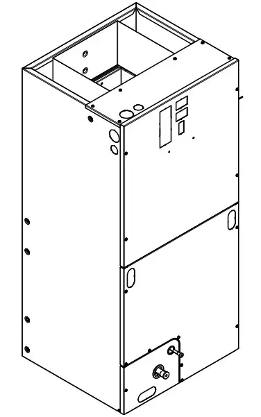
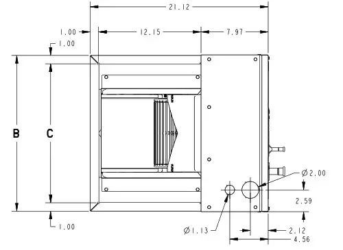
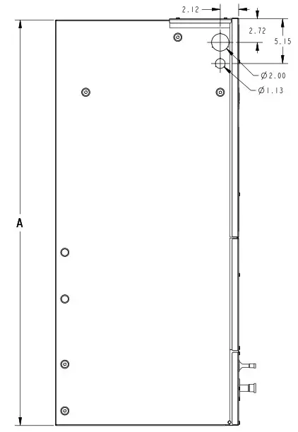
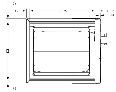
Outline Drawing
 |  |  |
| M I N I M UM U N I T CL EA R A NCE TABLE | |
| SER V I CE CLEA R A NCE (R ECOM M E N DED ) | |
| SIDES | 2″ |
| FRONT | 2 I” |
| BACK | 0″ |
| INLET DUCT | I” |
| OUTLET DUCT | N / A |
NOTE: THIS UNIT IS APPROVED FOR INSTALLATION CLEARANCES TO COMBUSTIBLE MATERIAL AS STATED ON THE UNIT RATING NAMEPLATE
ALL DIMENSIONS ARE REFERENCE DIMENSIONS
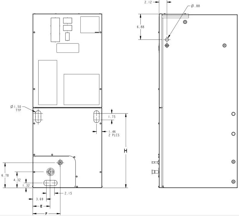
| PRODU CT DIMENSIONS | ||||||||||
| Air Handler Model | A | B | c | D | E | F | H | Flow Control | Gas Line Braze | |
| A4AH4E36A 1C30A | 51.27 | 23.50 | 21.50 | 21.75 | 7.01 | 9.66 | 24.59 | TXV | 7/8 | |
| All dimensions are in inches | ||||||||||
Product Specifications
| MODEL | A4AH4E36A1C30A |
| RATED VOLTS/PH/HZ | 208-230/ 1/60 |
| RATINGS(a) | See O.D. Specifications |
| INDOOR COIL -Type | Plate Fin |
| Rows – F.P.I. | 4 – 14 |
| Face Area (sq. ft.) | 4.59 |
| Tube Size (in.) | 3/8 |
| Refrigerant Control | TXV |
| Drain Conn. Size (in.) (b) | 3/4 NPT |
| DUCT CONNECTIONS | See Outline Drawing |
| INDOOR FAN – Type | Centrifugal |
| Diameter-Width ( n.) | 11X 8 |
| No. Used | 1 |
| Drive – No. Speeds | Direct – 5 Ccl |
| CFM vs. in. w.g. | See Fan Performance Table |
| No. Motors – H.P. | 1- 1/2 |
| Motor Speed R.P.M. | 1050 |
| Volts/ Ph/Hz | 208-230/ 1/60 |
| F.L. Amps | 4.1 |
| FILTER | |
| Filter Furnished? (b) | No |
| REFRIG ERANT | R-410A |
| Ref. Line Connections | Brazed |
| Coupling or Conn. Size – in. Gas | 7/8 |
| Coupling or Conn. Size – in. Liq. | 3/8 |
| DIM ENSIONS | H x W x D |
| Crated ( n.) | 52-3/4 x 27-1/2 x 25-1/2 |
| Uncrated | 51-3/8 x 23-1/2 x 21-1/8 |
| WEIGHT | |
| Shipping (Lbs.)I Net (Lbs.) | 155/ 144 |
(a) These Air Handlers are A.H.R.I certified with various Split System Air Conditioners and Heat Pumps (AHRI STANDARD 210/240). Refer to the Split System Outdoor Unit Product Data Guides for performance data.
(b) 3/4″ Male Plastic Pipe (Ref: ASTM 178576)
(c) ECM Motor
(d) Remote filter required.
Minimum Airflow CFM
| A4AH4E36A1C30A | ||
| Heater | Minimum Heat Speed Tap | |
| With Heat Pump | Without Heat Pump | |
| BAYHTR1504BRK, BAYHTR1504LUG, BAYHTR1505BRK, BAYHTR1505LUG | Low | Low |
| BAYHTR1508BRK, BAYHTR1508LUG, BAYHTR1510BRK, BAYHTR1510LUG | Med-High | Med-Low |
| BAYHTR1523BRK | Med-High | Med |
| BAYHTR1517BRK,BAYHTR3517LUG, BAYHTR3510LUG | High | Med |
Heater
BAYHTR1504BRK, BAYHTR1504LUG, BAYHTR1505BRK, BAYHTR1505LUG BAYHTR1508BRK, BAYHTR1508LUG, BAYHTR1510BRK, BAYHTR1510LUG BAYHTR1523BRK BAYHTR1517BRK, BAYHTR3517LUG, BAYHTR3510LUG
A4AH4E36A1C30A
Minimum Heat Speed Tap
With Heat Pump
Without Heat Pump
Low
Low
Med-High Med-High
High
Med-Low Med Med
A4AH4E36A1C-SUB-1A-EN
3
Heater Pressure Drop Table
Airflow CFM
1800 1700 1600 1500 1400 1300 1200 1100 1000 900 800 700 600
1
0.02 0.02 0.02 0.02 0.02 0.02 0.01 0.01 0.01 0.01 0.01 0.01 0.01
Number of Racks
2
3
Air Pressure Drop — Inches W.G.
0.04
0.06
0.04
0.06
0.04
0.06
0.04
0.06
0.04
0.06
0.04
0.05
0.04
0.05
0.03
0.05
0.03
0.04
0.03
0.04
0.03
0.02
0.02
4
0.14 0.14 0.13 0.12 0.12 0.11 0.10 0.09 0.09 0.08
Heater Racks
Heater Model
No. of Racks
BAYHTR1504
1
BAYHTR1505
1
BAYHTR1508
2
BAYHTR1510
2
BAYHTR1517
3
BAYHTR3510
3
BAYHTR3517
3
BAYHTR3515
3
BAYHTR1523
4
BAYHTR1525
4
4
A4AH4E36A1C-SUB-1A-EN
Performance and Electrical Data
1. See Product Data or Air Handler nameplate for approved combinations of Air Handlers and Heaters. 2. Heater model numbers may have additional suffix digits.
Table 1. Air Flow Performance
EXTERNAL STATIC (in w.g)
0.1 0.2 0.3 0.4 0.5 0.6 0.7
High 1492 1460 1426 1390 1352 1311 1269
A4AH4E36A1C30A
AIRFLOW
Speed Taps: 208 230 VOLTS
Med-High
Med
1418
1302
1385
1266
1349
1228
1311
1187
1271
1144
1229
1099
1184
1051
Med-Low 1268 1230 1190 1147 1101 1053 1003
1. Values are with wet coil, no filter, and no heaters 2. CFM Correction for dry coil = Add 3% 3. = Factory Setting 4. In downflow applications, airflow must not exceed 1600 cfm due to condensate blowoff. 5. Low = Tap 1, Med-Low = Tap 2, Med = Tap 3, Med-High= Tap 4, High = Tap 5
Low 1140 1096 1050 1002 952 899 845
A4AH4E36A1C-SUB-1A-EN
5
Performance and Electrical Data
Table 2. Electrical Data
A4AH4E36A1C30A
Heater Model No.
No. of Circuits/ Phases
Capacity kW BTUH
240 Volt
Heater Amps per
Circuit
Minimum Circuit
Ampacity
Maximum Overload Protection
No Heater
4.1 *
5
15
BAYHTR1504BRK BAYHTR1504LUG
1/1
3.8 13100
16.0
25
25
BAYHTR1505BRK BAYHTR1505LUG
1/1
4.8 16400
20.0
30
30
BAYHTR1508BRK BAYHTR1508LUG
1/1
7.7 26200
32.0
45
45
BAYHTR1510BRK BAYHTR1510LUG
1/1
9.6 32800
40.0
55
60
BAYHTR1517BRKCircuit 1 (a)
9.6 32800
40.0
55
60
2/1
BAYHTR1517BRKCircuit 2
4.8 16400
20.0
25
25
BAYHTR1523BRKCircuit 1 (a)
9.6 32800
40.0
55
60
2/1
BAYHTR1523BRKCircuit 2
9.6 32800
40.0
50
50
BAYHTR3510LUG
1/3
9.6 32800
23.1
33
35
BAYHTR3517LUG
1/3
14.4 49100
34.6
48
50
BAYHTR1517BRK
with single circuit power source kit
1/1
14.4 49100
60.0
83
90
BAYSPEKT201A
* = Motor Amps
(a) MCA and MOP for circuit 1 contains the motor amps.
Capacity kW BTUH
208 Volt
Heater Minimum Amps per Circuit
Circuit Ampacity
4.1 *
5
2.9 9800
13.8
22
3.6 12300 17.3
27
5.8 19700 27.7
40
7.2 24600 34.6
48
7.2 24600 34.6
48
3.6 12300 17.3
22
7.2 24600 34.6
48
7.2 24600 34.6
43
7.2 24600 20.0
30
10.8 36900 30.0
42
10.8 36900 51.9
73
Maximum Overload Protection
15 25
30
40
50
50
25
50
45 30 45
80
6
A4AH4E36A1C-SUB-1A-EN
Features and Benefits
· Galvanized metal cabinet with captured foil face insulation
· 2% or less air leakage · R-4.2 Insulating Value · Multi-Position UP/Down Flow, Horizontal Left /Right · ALL Aluminum Coil · Electric Heaters with polarized plug connections
(sold as accessory) · R-410A Thermal Expansion Valve · ECM Motor ( 3.0 5 Ton Models ) · Low Voltage Pigtail Connections
· Draw Through Design · Horizontal Drain pan · Single Color · Fused 24V Power · 5 year warranty · Optional extended warranty available
Important: Condensate management kit is required for all 5 ton air handler models installed in downflow applications.
A4AH4E36A1C-SUB-1A-EN
7
About Trane and American Standard Heating and Air Conditioning Trane and American Standard create comfortable, energy efficient indoor environments for residential applications. For more information, please visit www.trane.com or www.americanstandardair.com.
The manufacturer has a policy of continuous data improvement and it reserves the right to change design and specifications without notice. We are committed to using environmentally conscious print practices.
A4AH4E36A1C-SUB-1A-EN 06 Sep 2022 Supersedes (New)
©2022


