CMA DISHMACHINES EST-FL Low Temperature Door Type Dishwasher

Product Information
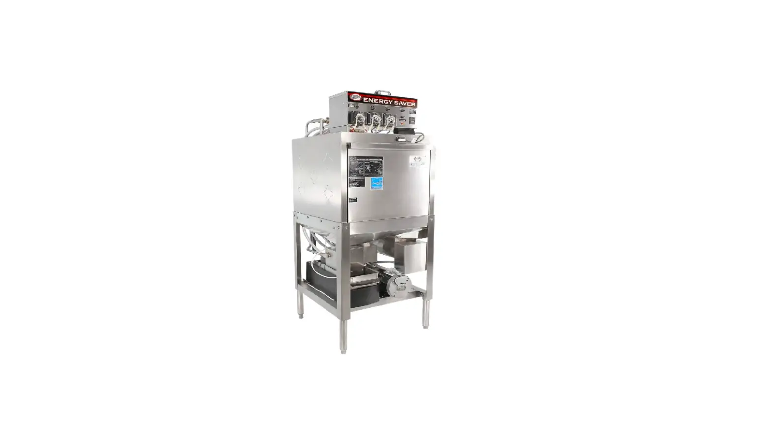
CMA DISH MACHINES EST-FL
The CMA DISHMACHINES EST-FL is a front-loading commercial dishwasher designed for washing dishes in a restaurant or food service establishment. The dishwasher comes with a range of parts and accessories, including a drain motor, pump assembly, spray arm, timer, peristaltic pump assembly, toggle switches, and more. The optional Sani Alarm provides an additional level of safety by alerting users when the sanitizer level is too low. The cabinet assembly is made up of various components, including the front loader wrapper panel, drain screen, tray tracks, and scrap trap drawer.
Product Usage Instructions
Before using the CMA DISHMACHINES EST-FL, it is important to read the user manual thoroughly and familiarize yourself with the various parts and accessories that come with the dishwasher. Follow these steps to use the dishwasher:
- Load dirty dishes into the dishwasher, making sure to stack them according to the manufacturer’s instructions.
- Add detergent and sanitizer to the appropriate compartments in the dishwasher.
- Close the dishwasher door and turn on the toggle switch to start the washing cycle.
- Monitor the dishwasher during the washing cycle to ensure that it is working correctly.
- When the cycle is complete, open the dishwasher door and remove the clean dishes.
- Clean and maintain the dishwasher regularly to ensure its proper functioning.
Note: If you have purchased the optional Sani Alarm, follow the manufacturer’s instructions for installation and use. The alarm will alert you when the sanitizer level is too low, indicating that it is time to add more sanitizer to the dishwasher.
Parts Manual
Initial Parts Kit (P/N 01100.84)
| P/N | DESCRIPTION | Qty |
| 00104.50 | Drain Motor, 120V 60Hz | 1 |
| 00108.83 | Drain Actuator Arm (V) | 1 |
| 00109.60 | Drain Actuator Shaft (V) | 1 |
| 00115.87 | Drain Screen | 1 |
| 00120.02 | Thermometer | 1 |
| 00121.60 | Drain Diaphragm | 1 |
| 00200.10 | Pump Assembly, 110/220V 60Hz | 1 |
| 00206.30 | Pump Seal Kit | 1 |
| 00304.06 | Spray Arm | 1 |
| 00308.50 | Spray Arm End Plug, SS | 1 |
| 00341.00 | Spray Arm Bearing | 1 |
| 00406.00 | Control Box Light, .5” Diameter, Red | 1 |
| 00407.83 | Timer, 90 Sec, 8 Cam | 1 |
| 00416.00 | Peristaltic Pump Assembly, 120V/60Hz | 1 |
| 00425.51 | Chemical Tubing Blue | 1 |
| 00425.53 | Chemical Tubing Red | 1 |
| 00425.54 | Chemical Tubing White | 1 |
| 00470.10 | Toggle Switch Rubber Boot | 3 |
| 00471.10 | Toggle Switch, Off/On, 20-Amp | 1 |
| 00475.70 | Toggle Switch, DPDT, 15-Amp, Delimer | 1 |
| 00631.00 | Ice Cube Relay, 120V | 1 |
| 00707.00 | 1/2″ Water Solenoid Repair Kit, JE | 1 |
| 00738.10 | Solenoid Coil, JE, 120V ( ¾” & ½” ) | 1 |
| 00938.82 | 1/2” Drain Bushing, Brass (V) | 2 |
| 00966.10 | 10-32X1/4 Hexhead SS Bolt | 1 |
| 02257. 00 | Squeeze Tube Norprene | 1 |
| 03415.45 | Flex-Tight Fitting | 1 |
| 03470.00 | Toggle Switch, Momentary, Screw Terminals | 1 |
| 03623.00 | 1/2” Vacuum Breaker Repair Kit, Watts | 1 |
| 04103.14 | Drain Valve Spring | 1 |
Optional Sani Alarm
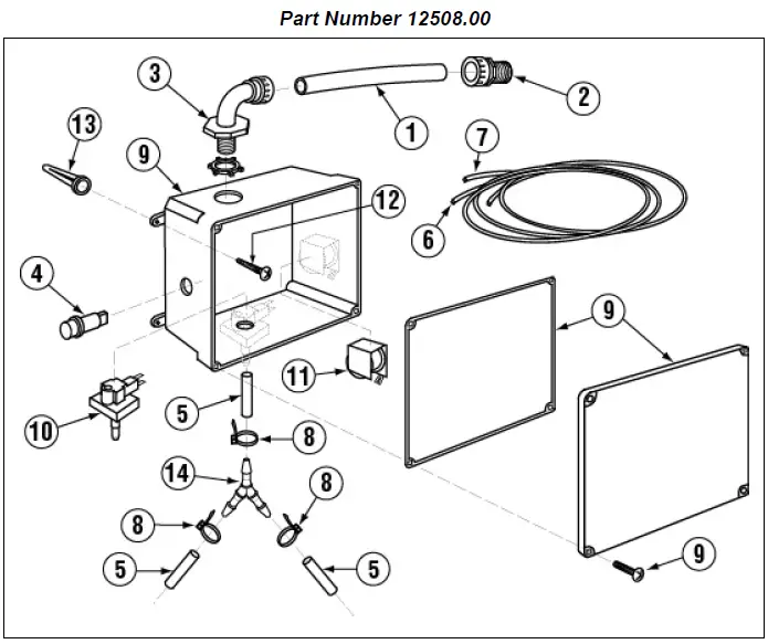
Exploded View
| ITEM NO. | NO. REQ’D | P/N | DESCRIPTION |
| 1 | 3 | 00400.00 | Conduit, 3/8” Sealtite |
| 2 | 1 | 00401.00 | S.T. 3/8” Straight Connector |
| 3 | 1 | 00402.00 | S.T. 90 Degree 3/8” Connector |
| 4 | 1 | 00406.00 | Control Box Light, .5” Diameter, Red |
| 5 | 1 | 00435.00 | Squeeze Tube, 8” |
| 6 | 1 | 00521.00 | Wire, 18 Gauge, Orange, 6 ft. |
| 7 | 1 | 00531.00 | Wire, 18 Gauge, White, 6 ft. |
| 8 | 5 | 00931.00 | Wire Tie, Small |
| 9 | 1 | 12510.00 | Sanitizer Alarm Box Assembly |
| 10 | 1 | 12511.50 | Sanitizer Low Level Vacuum Switch |
| 11 | 1 | 12512.00 | Sanitizer Alarm Buzzer, 120 Volts |
| 12 | 4 | 40126.10 | #10 x 3/4″ Sheet metal Screw |
| 13 | 4 | 40127.00 | Wall Anchors |
| 14 | 1 | 00426.00 | Y Hose Connector, 3/16” |
Exploded View Drawings
Cabinet Assembly

| ITEM NO. | NO. REQ’D | P/N | DESCRIPTION |
| 1 | 1 | 01512.10 | EST Front Loader Wrapper Panel |
| 2 | 1 | 01512.00 | EST Front Loader Wrapper |
| 3 | 1 | 00115.87 | Drain Screen |
| 4 | 18 | 00906.00 | 1/4-20 x 1/2″ Hex head Bolt |
| 5 | 1 | 01505.51 | EST Front Loader LH Tray Track |
| 6 | 1 | 01505.50 | EST Front Loader RH Tray Track |
| 7 | 6 | 00940.50 | 10-32 x 3/8″ Truss Head Screw |
| 8 | 1 | 00120.40 | EVA Power Drain Cover |
| 9 | 4 | 01145.00 | Leg Ass’y 10″ w\Adjustable Socket |
| 10 | 4 | 00914.00 | 1/4-20 x 3/4″ Hex Head Bolt |
| 11 | 1 | 01577.21 | S/S Scrap Trap Drawer |
| 12 | 1 | 01573.30 | Sani Mount/Drain Lid |
| 13 | 1 | 01577.10 | Scrap Trap Body |
| 14 | 1 | 1502.90 | EST Pan |
| 15 | 1 | 01579.50 | EVA Splash Card |
| 16 | 4 | 01572.10 | SS Leg |
| 17 | 1 | 01502.95 | EST Stand |
| 18 | 4 | 01310.00 | Bullet Foot |
| 19 | 1 | 00120.02 | Thermometer (Bi Metal) |
| 20 | 1 | 0556.10 | Reed Switch – ISI |
| 21 | 1 | 14558.30 | EST Front Loader Body Magnet Holder |
| 22 | 2 | 00557.80 | Door Magnet (L-1X/CMA-180UC/GL-X) |
| 23 | 1 | 14506.30 | EST Front Loader Gasket Bracket |
Door Assembly
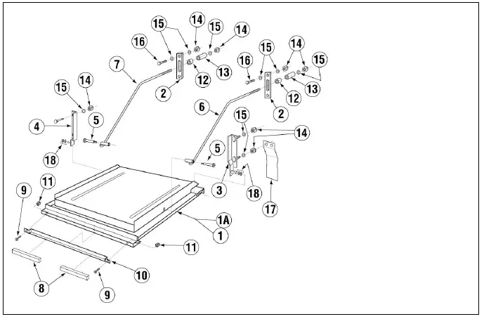
| ITEM NO. | NO. REQ’D | P/N | DESCRIPTION |
| 1 | 1 | 14506.00 | Door for L-1X16 |
| 2 | 2 | 04517.60 | Door Support Rod Block |
| 3 | 1 | 14570.00 | Door Hinge (RH) |
| 4 | 1 | 14570.50 | Door Hinge (LR) |
| 5 | 2 | 04919.00 | Door Rod Screw Pin for Door |
| 6 | 1 | 04918.60 | Door Support Rod Right |
| 7 | 1 | 04919.50 | Door Support Rod Left |
| 8 | 3 | 00557.80 | Door Magnet |
| 9 | 2 | 00970.60 | 6 32 x 1/2″ Flathead Screw |
| 10 | 1 | 14558.61 | Door Magnet Holder |
| 11 | 2 | 00965.00 | 06-32 Lock Nut |
| 12 | 2 | 00605.30 | Door Rod Spacer |
| 13 | 2 | 04517.15 | Door Stop (Parallel) |
| 14 | 10 | 00912.00 | 1/4″-20 Nylon Lock Nut |
| 15 | 14 | 00924.00 | 1/4″ SS Washer |
| 16 | 4 | 00914.10 | 1/4″-20 x 5/8” Hex Head Bolt |
| 17 | 2 | 14518.00 | Splash Guard |
| 18 | 4 | 00924.00 | 1/4 SS Washer |
Control Box Assembly
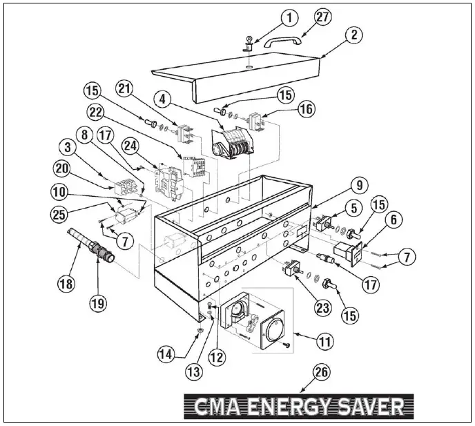
Note: Wiring Harness (V)—Part Number 00414.82—(not shown).
| ITEM NO. | NO. REQ’D | P/N | DESCRIPTION |
| 1 | 1 | 00449.00 | Lock and Key |
| 2 | 1 | 01504.17 | Control Box Lid |
| 3 | 5 | 00911.50 | 8-32 x 3/8” Pan Head Screw |
| 4 | 1 | 00407.83 | Timer, 90 Seconds |
| 5 | 1 | 03470.01 | Toggle Switch, Momentary |
| 6 | 1 | 03408.50 | Counter (Face Mount) |
| 7 | 4 | 00907.00 | 6-32 x 1/2″ SS Pan Head Screw |
| 8 | 4 | 00917.00 | 8-32 PM Nut |
| 9 | 1 | 01503.19 | Control Box Body |
| 10 | 4 | 00916.00 | 6-32 pm nut |
| 11 | 3 | 00415.00 | Peristaltic Pump Assembly* |
| 12 | 4 | 00906.00 | 1/2-20 x 1/2″ Hex Head Bolt |
| 13 | 4 | 00924.00 | 1/4″ SS Washer |
| 14 | 4 | 00912.00 | 1/4-20 Nylon Lock Nut |
| 15 | 5 | 00470.10 | Toggle Switch Boot |
| 16 | 1 | 00471.10 | Toggle Switch Off/On 20 Amp |
| 17 | 2 | 00406.00 | Control Box Light, 120V, 60Hz |
| 18 | 1 | 00400.00 | Conduit, 3/8” Sealtite |
| 19 | 3 | 00401.00 | S.T. 3/8” Straight Connector |
| 20 | 1 | 00454.10 | 3-Pole Socket Terminal Block |
| 21 | 1 | 00475.70 | Toggle Switch, 15 Amp |
| 22 | 1 | 13012.15 | Contactor 5 kW GL-X 120V |
| 23 | 4 | 03470.00 | Toggle Switch |
| 24 | 1 | 00404.82 | Contactor Relay |
| 25 | 1 | 00631.00 | Ice Cube Relay |
| 26 | 1 | 06232.25 | CMA Energy Saver Label |
| 27 | 1 | 00535.00 | Control Box Lid Handle |
- See section 1.3.8 Peristaltic Pump Assembly for details
Pump Assembly
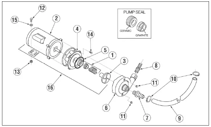
| ITEM NO. | NO. REQ’D | P/N | DESCRIPTION |
| 1 | 1 | 00206.30 | Pump Seal Kit |
| 2 | 1 | 00201.00 | Pump Motor 1Hp 115/208- 230V |
| 3 | 1 | 03222.10 | Impeller (Universal) Open |
| 4 | 1 | 04207.10 | Pump Base |
| 5 | 1 | 03226.00 | Pump O Ring Gasket |
| 6 | 1 | 04207.20 | Pump Cover |
| 7 | 1 | 50302.40 | 1 ¼ MIP X 1″ Barb Fitting |
| 8 | 1 | 50302.06 | 1″ MPT X 1″ Barb PVC Sch 80 |
| 9 | 1 | 03108.61 | Tranfer Hose 1″ |
| 10 | 2 | 03101.00 | Hose Clamp # 16 1″ |
| 11 | 2 | 00238.00 | 3/8 Male Plug |
| 12 | 1 | 00906.00 | 1/4-20 X 1/2 Hexhead Bolt |
| 13 | 1 | 00912.00 | 1/4-20 Nylon Lock Nut |
| 14 | 4 | 00921.00 | 3/8-16 X 3/4 SS Hexhead Bolt |
| 15 | 1 | 00924.00 | 1/4 SS Washer |
| 16 | 1 | 00200.10 | Pump Assy 110/220V 60Hz open |
Plumbing System Assembly
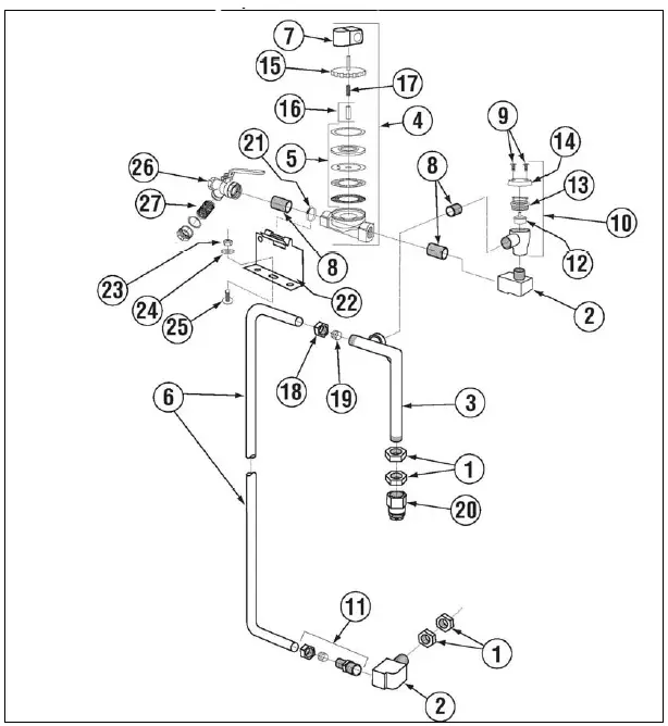
| ITEM NO. | NO. REQ’D | P/N | DESCRIPTION |
| 1 | 4 | 00721.00 | 1/2″ Jamb Nut |
| 2 | 2 | 00745.00 | 1/2″ Street Elbow |
| 3 | 1 | 00770.00 | Water Inlet Elbow Assy |
| 4 | 1 | 03603.10 | 1/2″ Water Solenoid Assembly, J/E* |
| 5 | 1 | 00707.00 | 1/2″ Water Solenoid Repair Kit |
| 6 | 1 | 00796.20 | Flush Tube |
| 7 | 1 | 00738.10 | Water Solenoid Coil |
| 8 | 2 | 00742.00 | 1/2″ x 1-1/2” Brass Nipple |
| 9 | 2 | 00421.51 | 6-32 x 1/4″ Pan Head Screw |
| 10 | 1 | 03624.00 | Vacuum Breaker Assembly, Watts** |
| 11 | 1 | 00760.00 | 5/8” Compression x 1/2″ MIP Adapter |
| 12 | 1 | 03623.00 | 1/2″ Vacuum Breaker Repair Kit |
| 13 | 1 | 03624.25 | 1/2″ Vacuum Breaker Bonnet, Brass |
| 14 | 1 | 00739.50 | Vacuum Breaker Cap, SS (fits ½” or ¾”) |
| 15 | 1 | 03603.20 | 1/2″ Water Solenoid Bonnet |
| 16 | 1 | 00786.00 | Water Solenoid Valve Plunger w/Spring |
| 17 | 1 | 00706.10 | Valve Plunger, Spring Only |
| 18 | 1 | 00770.10 | 5/8 Compression Fitting Nut |
| 19 | 1 | 00770.20 | 5/8 Compression Fitting Ring |
| 20 | 1 | 00748.00 | Sprinkler Head |
| 21 | 1 | 03101.45 | Hose Clamp #4 Size #002 SS |
| 22 | 1 | 14508.50 | Plumbing Bracket |
| 23 | 1 | 03801.00 | 10-32 Lock Nut |
| 24 | 2 | 00924.00 | 1/4 SS Washer |
| 25 | 1 | 00940.50 | 10-32 x 3/8 Truss Head Screw |
| 26 | 1 | 41062.00 | 1/2 Strainer Ball Valve NPT |
| 27 | 1 | 41062.10 | 1/2 Ball Valve Strainer Only |
Spray System Assembly
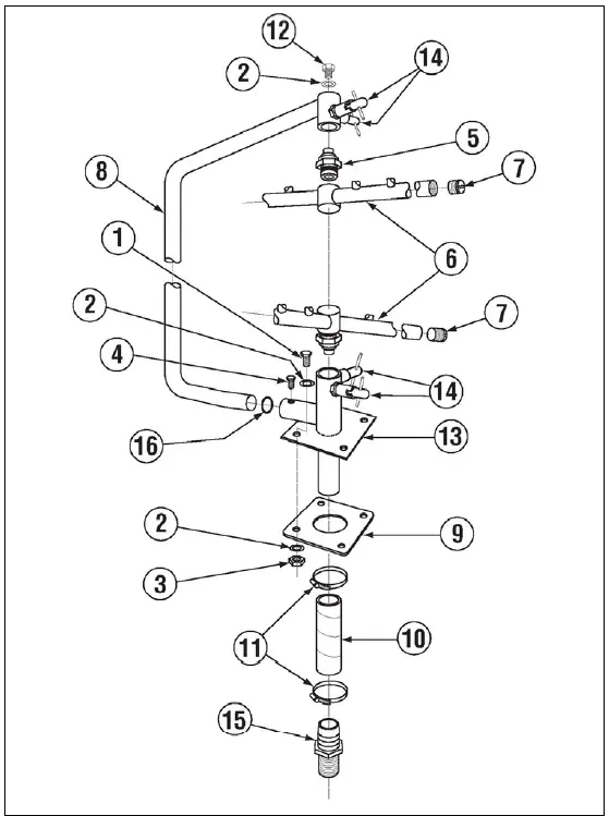
| ITEM NO. | NO. REQ’D | P/N | DESCRIPTION |
| 1 | 4 | 00914.00 | 1/4-20 x 3/4″ Hex Head Bolt |
| 2 | 9 | 00924.00 | 1/4″ SS Washer |
| 3 | 4 | 00912.00 | 1/4-20 Nylon Lock Nut |
| 4 | 1 | 00966.10 | 10-32 x 1/4″ Hex Head SS Bolt |
| 5 | 2 | 00341.00 | Spray Arm Bearing |
| 6 | 2 | 00304.07 | Spray Arm A/C Series |
| 7 | 4 | 00308.50 | Spray Arm End Plug SS |
| 8 | 1 | 00305.20 | Spray Manifold, EST/N- EVA |
| 9 | 1 | 04306.00 | Square Manifold Gasket |
| 10 | 1 | 03108.61 | Transfer Hose 1” |
| 11 | 2 | 03101.00 | Hose Clamp |
| 12 | 1 | 00905.82 | 1/4-20 x 3/8” Truss Head Bolt |
| 13 | 1 | 00357.20 | Lower Spray Base, N EVA 2007 |
| 14 | 4 | 0363.50 | Spray Base Pull Lock Pin |
| 15 | 1 | 50302.06 | 1″ MPT X 1″ Barb PVC Schedule 80 |
| 16 | 1 | 00302.84 | Spray Base 0-Ring, E-VA |
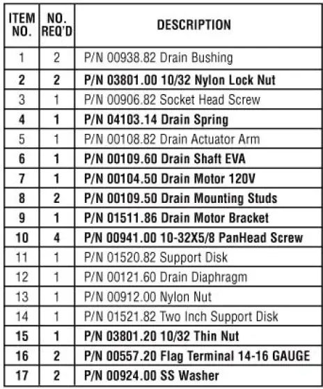
Power Drain Assembly (Prior to 11-2007)
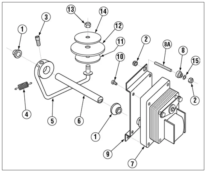
| ITEM NO. | NO. REQ’D | P/N | DESCRIPTION |
| 1 | 2 | 00938.82 | 1/2″ Drain Bushing, Brass (V) |
| 2 | 4 | 03801.00 | 10-32 Lock Nut |
| 3 | 1 | 00906.82 | 1/4-20 x 5/8” Socket Head Screw |
| 4 | 1 | 04103.14 | Drain Spring (V) |
| 5 | 1 | 00108.83 | Drain Actuator Arm (includes #3) |
| 6 | 1 | 00109.60 | Drain Actuator Shaft (V) |
| 7 | 1 | 00104.50 | Drain Motor, 120V 60Hz |
| 8 | 2 | 00109.40 | Shoulder Nut, SS |
| 8A | 2 | 00109.50 | 10-32 x 1” Stud |
| 9 | 1 | 01511.86 | Drain Motor Bracket |
| 10 | 2 | 00941.00 | 10-32 x 5/8” Pan Head Screw |
| 11 | 1 | 01520.82 | Diaphragm Support Disk, 1-1/8” |
| 12 | 1 | 00121.60 | Drain Diaphragm |
| 13 | 1 | 00912.00 | 1/4-20 Nylon Lock Nut |
| 14 | 1 | 01521.82 | Diaphragm Support Disk, 2” |
| 15 | 2 | 04806.00 | #10 Brass Washer |
POWER DRAIN ASSEMBLY INSTRUCTIONS
Power Drain Retrofit Kit p/n 00104.95 (11-14-07 to Current)
POWER DRAIN KIT
P/N 00104.95
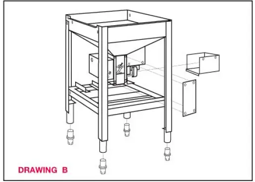
- Remove drain lid and power drain cover (see drawing B).
- Remove hardware securing drain motor. Discard all hardware holding motor in place.
- Remove and discard motor bracket from motor, but save two (#10) 10-32 screws.
- Install hardware (#2, #8, #15). Thread two (#8) studs through tank and secure in place with (#2) nylon lock nuts. On the outside of tank install (#15) thin nut onto the (#8) stud and secure. NOTE: The (#15) thin nut serves a very important purpose in drain function.
- From kit install new drain motor bracket to drain motor with two saved (#10) 10-32 screws.
- Remove drain shaft by loosening (#3) screw on (#5) drain actuator arm. Discard drain shaft.
- Install the new (#6) drain shaft from the kit and align drain actuator arm to the tank using the (#3) set screw. Make sure the flat side of the (#6) drain shaft has the (#3) set screw tightening against it.

- Install (#4) drain spring properly on drain shaft and pay particular attention to the positioning of the long arm on spring. The long arm will rest against the top right side of drain motor bracket. (See drawing A). Install short end of spring into slot of drain shaft. (See figure C).

- Align the shaft of the (#7) drain motor with (#6) drain actuator shaft slot as motor is placed into position. Drain motor bracket with motor attached is secured to (#8) studs using (#2 and #17) nylon lock nuts and washers.
- Grease the drain shaft and (#1) drain bushings. Replace drain lid and drain cover. When drain kit has been completed, energize drain several times and check its function. NOTE: Remove electrical spade connectors from wires leading to drain motor and replace with two (#16) flag terminals supplied in drain kit. This will allow proper clearance between drain lid and flag terminals.
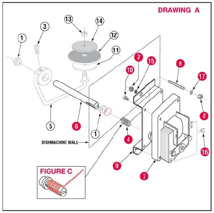
NOTE: Items in bold are included in the Power Drain Kit. “All items in power drain kit must be used for drain to operate properly”.
Peristaltic Pump Assembly
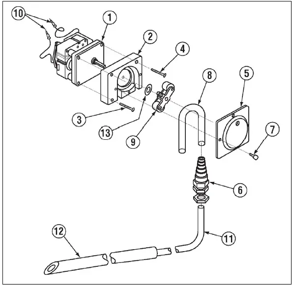
| ITEM NO. | NO. REQ’D | P/N | DESCRIPTION |
| 1 | 1 | 00416.00 | Peristaltic Pump Motor |
| 2 | 1 | 00417.10 | Peristaltic Pump Block |
| 3 | 2 | 00919.00 | 10-32 x 1-1/2” Pan Head Screw |
| 4 | 1 | 00918.10 | 10-32 x 1-1/2” Fillister Head Screw |
| 5 | 1 | 00418.00 | Peristaltic Pump Block Cover |
| 6 | 1 | 03415.50 | Flex-Tight Fitting |
| 7 | 4 | 00911.00 | 8-32 x 1/2″ Pan Head Screw |
| 8 | 1 | 2257.00 | Squeeze Tube |
| 9 | 1 | 00419.00 | 2-Bearing Rotor Assembly |
| 10 | 2 | 00448.00 | Barrel Connector, Male |
| 11 | 1 | 00425.51 | Chemical Tubing, Blue |
| 1 | 00425.53 | Chemical Tubing, Red | |
| 1 | 00425.54 | Chemical Tubing, White | |
| 12 | 3 | 00443.00 | Tube Stiffener |
| 13 | 1 | 00422.50 | Rotor Spacer |
Sustainer Heater (Optional)
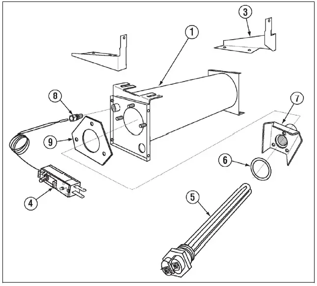
| ITEM NO. | NO. REQ’D | P/N | DESCRIPTION |
| 1 | 1 | 17550.20 | Booster Tank |
| 2 | 1 | 17604.06 | EST Ventless Front Heater Bracket |
| 3 | 1 | 17605.00 | EST Ventless Back Heater Bracket |
| 4 | 1 | 13417.92 | Thermostat |
| 5 | 1 | 15417.30 | Screw Plug Heater 1.5kW, 115V |
| 6 | 1 | 00703.00 | O-Ring Gasket |
| 7 | 1 | 17550.30 | EST FL Booster Tank Adapter |
| 8 | 1 | 40116.00 | 1/4 Comp x 1/4 MIP Fitting |
| 9 | 1 | 15518.13 | Sustainer Heater Gasket |
Contacts
- CMA DISH MACHINES
- 12700 KNOT STREET
- GARDEN GROVE, CALIFORNIA 92841
- 800-854-6417
- FAX: 714-895-2141
- 12700 Knott Avenue
- Garden Grove, CA 92841
- For Questions Call: 800-854-6417
- 714-898-8781
- FAX: 714-895-2141
- www.cmadishmachines.com


