![]() SPH 4000-1 0000TL3 BH-UP
SPH 4000-1 0000TL3 BH-UP
Quick Guide
Overview
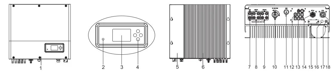
| 1. Front panel 2. Double color LED 3. LCD screen 4. Push button 5. Magnetic devices 6.Heat sink | 7. Battery connector 8. PVA connector 10. PV switch 9. PVB connector 11. USB port 12. Dry connector | 13. Communication ports 14. AC grid connector 15. Reserved hole 16. Breathable valve 17. Grounding screw 18. EPS connector |
![]() Note:
Note:
- Only three-phase meter supports current direction detection.
- Function introduction of communication ports(14) in the follow.
![]() Note:
Note:
- This file will be updated from time to time due to product upgrades or other reasons. Unless otherwise agreed, this document is intended as a guide only. All information and suggestions do not constitute an express or implied warranty. The final interpretation of the content is at Growatt.
- This document is for quick guidance installation only. For details, please refer to the User Manual.
- Machine damage caused by failure to follow the content is not covered by the warranty.
Installation
System Overiew 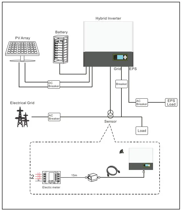
![]() Note:
Note:
The installation of this hybrid system needs to comprehensively consider the position of the battery and the power collector.
2.1 Installation requirements 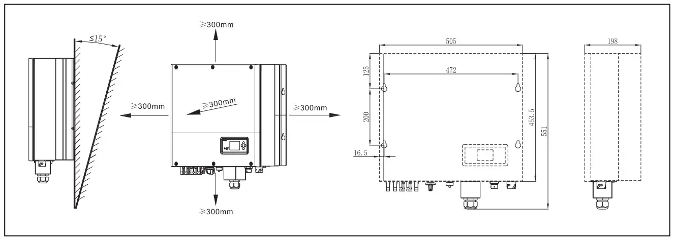 2.2 Wair mounting
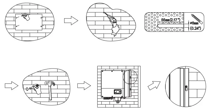
![]() Note:
Note:
Be careful : Avoid water and electricity pipes when punching holes in the wall, otherwise it may be dangerous.
2.3 communication module installation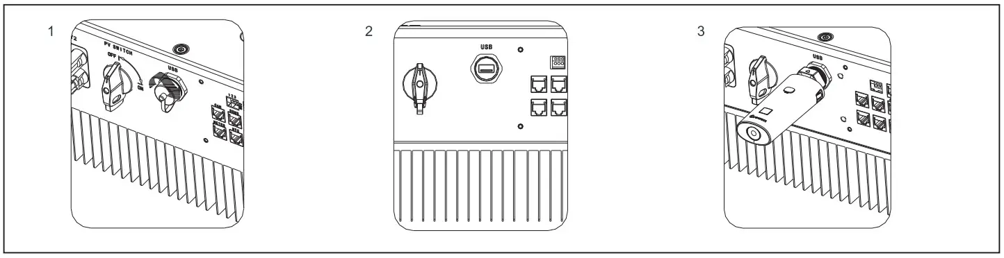 Follow the installation steps:
- Remove the USB waterproof cover.
- Plug in the communica tion module.
Connecting cables
Please prepare the cable before connecting as follows.
| Number | Cable name | Type | Recommend module |
| 1 | Grounding wire | Single multi-core yellow-green copper wire | Wire diameter>AWG10 |
| 2 | AC output wire | Two or three different color multi-core copper wire | Wire diameter>AWG12 |
| 3 | PV input wire | Photovoltaic dedicated cable (such as PV1-F) | 4mm2 – 6mm2 |
| 4 | Battery input wire | Red and black multi-core copper | Wire diameter>AWG10 |
| 5 | Communication wire | CAT5E | / |
![]() Notice.
Notice.
- Lithium battery has its own power line and communication line, so please use them directly.
- Hybrid inverter include the basic communication line. So please use them directly.
- Please make sure all the switches off before connection. For your safety, please do not operation when power on.
3.1 Grounding 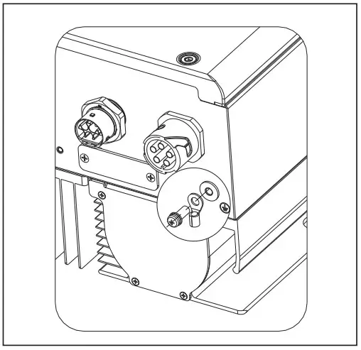
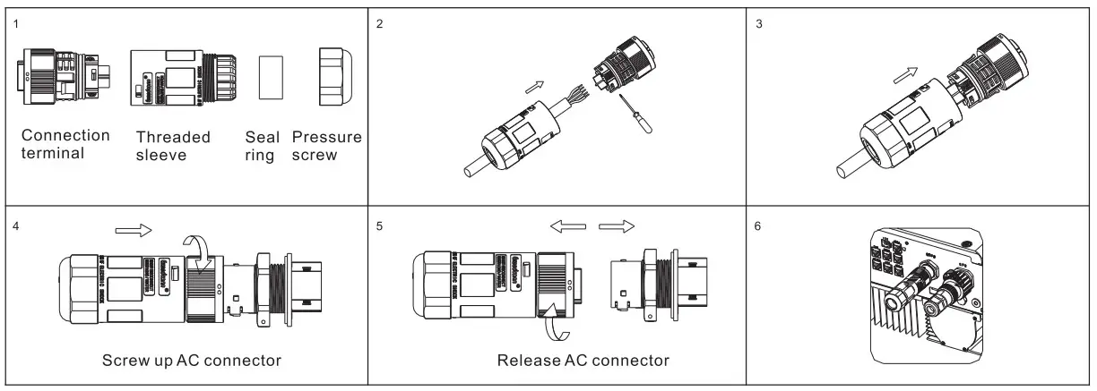 3.2 AC GRID and EPS output connection
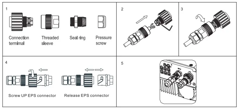
3.3 DC connection
3.3.1 PV and Battery input terminal installation 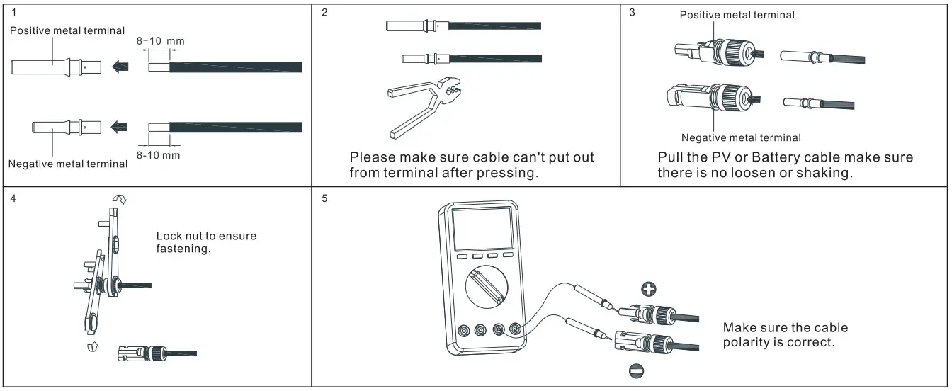 3.3.2 Plug in PV terminal
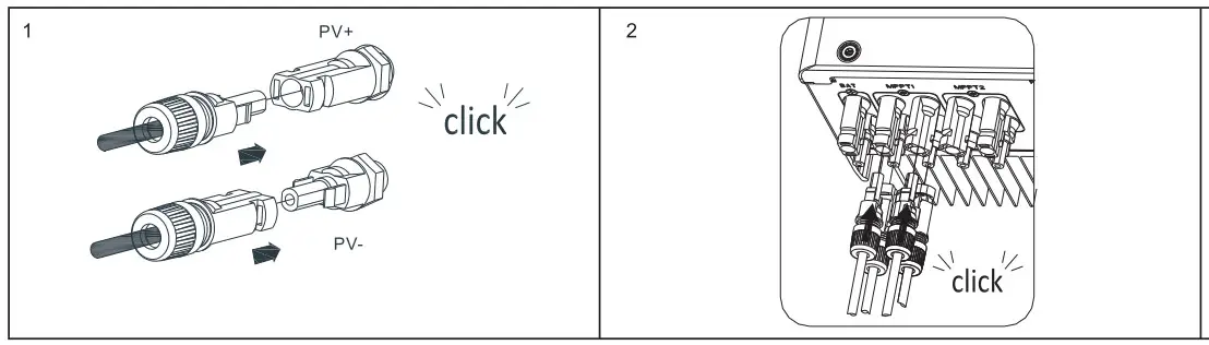
Notes:
- Please make sure the PV input voltage/current not beyond the specification before plug in.
- When installing the PV terminal, pay attention to the distinction between the positive and negative terminals and the one-to-one correspondence between the terminals and hybrid inverter.
- When the terminal is docked, there is a click sound. After the terminal is docked, gently pull the PV cable to observe whether the terminal is shaking or not.
3.3.3 Plug in Battery terminal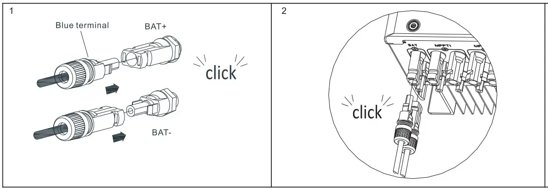 Notes.
- Turn off the battery cabinet switch and disconnect the CAN communication cable before inserting. Make sure that the battery input voltage/current does not exceed the specifications.
- When installing the battery terminal, pay attention to the distinction between the positive and negative terminals and the one-to-one correspondence between the terminals and hybrid inverter.
- When the terminal is docked, there is a click sound. After the terminal is docked, gently pull the battery cable to observe whether the terminal is shaking or not.
3.3.4 Communication cables installation 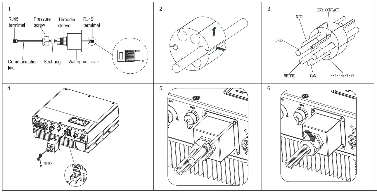 When all the communication lines are installed, push the waterproof caver into the bottom, lock the screws fixed to the frame, and finally lock the waterproof cap.
Post-instaiaton check
| Number | Acceptance Criteria | Number | Acceptance Criteria |
| 1 | Hybrid inverter is installed correctly and firmly | 2 | ShineWiFi-X or Shinelink or GPRS is installed correctly and firmly. |
| 3 | Cable wiring is reasonable, meets the requirements, no broken skin, etc. | 4 | The ground wire confirms the connection and is reliable. |
| 5 | All switches off | 6 | All wires are correct and securely connected. |
| 7 | Cable tie port trimming, no sharp corners, etc. | 8 | All exposed terminals are well protected, no vacant ports. |
| 9 | Pay attention to packing all the residual materials. |
On off hybrid inverter
![]() Notes:
Notes:
Before power on, please make sure all of the voltage and current are in the range of specification of hybrid inverter. Otherwise it will be damage to hybrid inverter.
Follow are the steps of turn on actions:
- Turn on the switch between Grid and hybrid inverter.
- Turn on battery and the switch between battery and hybrid inverter.
- Turn on PV switch.
- Turn on Battery switch.
- If need to setup hybrid inverter. Please turn to user manual of hybrid inverter for detail description.
- The shutdown steps are opposite to the above order.
- The hybrid has an installation diagnosis function, please run “DiagnoseFun” after the installation is completed.
Status of hybrid inverter
Customer can read more information by push button. Follow are the instruction of button and LED.
| Mark | Description | Explanation | |
| Push-button | Operation of display screen and set system | ||
| Status symbol of SPH | Green light on | SPH run normally | |
| Red light on | Fault state | ||
| Green light blinking | Alarm state | ||
| Red light blinking | Software updating | ||
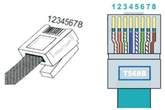
Definition of RJ45 Port Pin
| No. | CAN | METER | COM | DRMS | NTC | 485-1/485-2 | 485-3 |
| 1 | / | RS485B | DRY+ | DRM1/5 | GND | RS485B | RS485B |
| 2 | / | GND | / | DRM2/6 | GND | GND | GND |
| 3 | / | / | DRY- | DRM3/7 | GND | / | / |
| 4 | CANH | / | / | DRM4/8 | GND | RS485B | / |
| 5 | CANL | RS485A | / | REF | NTC | RS485A | RS485A |
| 6 | GND | / | / | COM | NTC | / | / |
| 7 | / | / | / | / | NTC | RS485A | / |
| 8 | WAKEUP | / | / | / | / | RS485B | / |
Service and contact
Shenzhen Growatt New Energy Co., Ltd
4-13/F,Building A,Sino-German(Europe) Industrial Park, Hangcheng Ave,Guxing Community, Xixiang Subdistrict, Bao’an District, Shenzhen, China
T +86 0755 27471942
E [email protected]
W www.ginverter.com
 http://oss.growatt.com:80//common/downLoadSms/d00e8940-e7fc-454a-be97-e9cc53f14824
GR-UM-216-4-02 ![]()
![]() Growatt New Energy
Growatt New Energy


