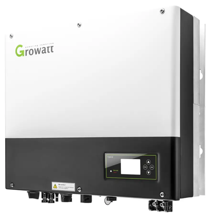
GROWATT SPH Series 5KW Hybrid Inverters
Introduction
In this installation guide we will give you a step-by-step overview on how to install a hybrid inverter. The focus will be on how to install the Smart Meter and connect the inverter to the battery.
Hybrid Inverter & AC Coupler/retrofit Models
Growatt has a wide assortment of hybrid inverters and AC couplers. This guide will discuss the necessities and step-by-step installation for the following models:
- MIN 2500-6000TL-XH / MIN 2500-6000TL-XA
- MOD 3000-10000TL3-XH
- SPH 3000-6000 BL / BL-UP
- SPH 5000-10000 BH / BH-UP
- SPA 5000-10000 BH / BH-UP
Please note that Growatt cannot guarantee the system will work properly if batteries from a 3rd party is used.
MIN 2500-6000TL-XH
The MIN TL-XH/XA inverters use the same XH battery system with BMS controller BDC- 95045-A1 and ARK 2.5H-A1. All our inverters are compatible with the same meters. See the tables below for an overview of compatible batteries and meters.
BATTERY COMPATIBILITY
At this moment in time (May 2023) the MIN-XH are only compatible with Growatt ARK-HV batteries. Support for different types of batteries will be announced at a later date.
| BMS controller | BDC 95045-A1 | Supports 2-7 batteries |
| Battery | ARK 2.5H-A1 | Needs at least 2 batteries |
| Battery Base | ARK Battery Base | Necessary to install the batteries on the ground as is recommend. |
| Battery Cable | ARK XH Battery Cable | Every system needs 1 battery cable to connect the inverter to the BMS controller |
| Series cable | ARK 2.5H-A1 Series cable | Only necessary to connect a 2nd set/base of ARK 2.5H-A1 batteries |
METER COMPATIBILITY
| Brand meter | Type | Sold as | Connection | Suited for delta/split phase | COM adres | RS485A place | RS485B place |
| Eastron | SDM230 | SPM | In-line | No | 1 | 5 / A | 6 / A |
| SDM630V2 | TPM | In-Line | Yes | 2 | A | B | |
| SDM630CT | TPM-CT | External CT | No | 2 | A | B | |
| Chint | DDSU666 | SPM | In-Line | No | 3 | 24 | 25 |
| DTSU666 | TPM | In-Line | Yes | 4 | 24 | 25 | |
| DTSU666CT | TPM-CT | External CT | No | 4 | 24 | 25 |
It is recommended to check if the right equipment has been bought and delivered to the client.
Installing ARK 2.5H-A1 Batteries and Connecting the BMS
The connection of the ARK2.5H-A1 batteries is shown below. Make sure that the cables are facing the right orientation. After securely connecting, there is a ‘click’ sound.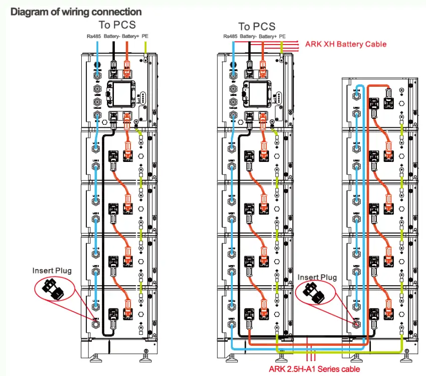
Note: It is not recommended to install a DC circuit breaker between the battery system and the hybird inverter system, If you want to install a DC circuit breaker with rated working voltage greater than 1000V and rated working current greater than 63A, do not operate the DC circuit breaker with power on, otherwise the machine may be damaged.
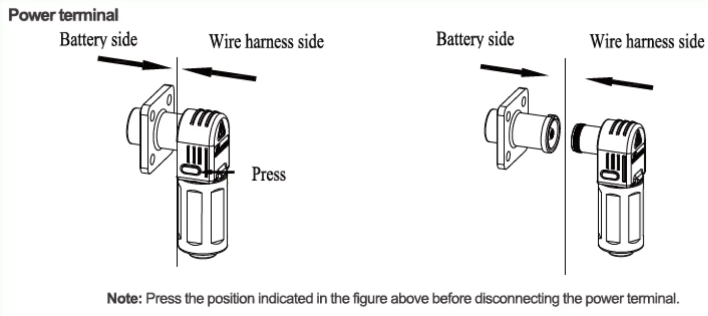
The cable can be removed by pressing the buttons on the side and pulling softly. If placing and removing the cable takes a lot of force, you are probably placing it in the wrong orientation or you are using the wrong cable, and it may damage the connectors.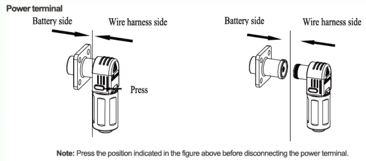
IMPORTANT: Do not forget to plug in the Insert plug in the last battery. If the Insert plug is not connected, the system will not work correctly.
TIP: If the Insert plug is missing, you can make one yourself by taking the end of a standard RJ45 connector, and shorting pin 4 and 5, while leaving the rest unconnected/open.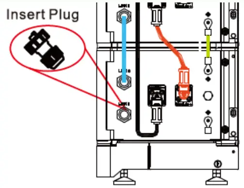
The communication cable from the BMS goes from the BMU port to Link 0 of the first battery. Please make sure all cables are properly inserted.
The INV port on the BMS leads to the SYS COM port of the inverter.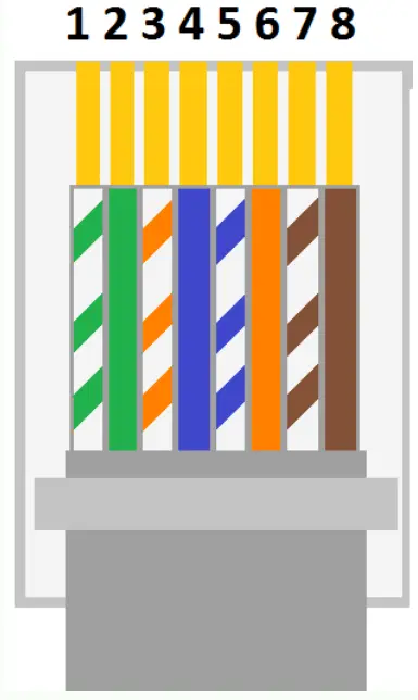
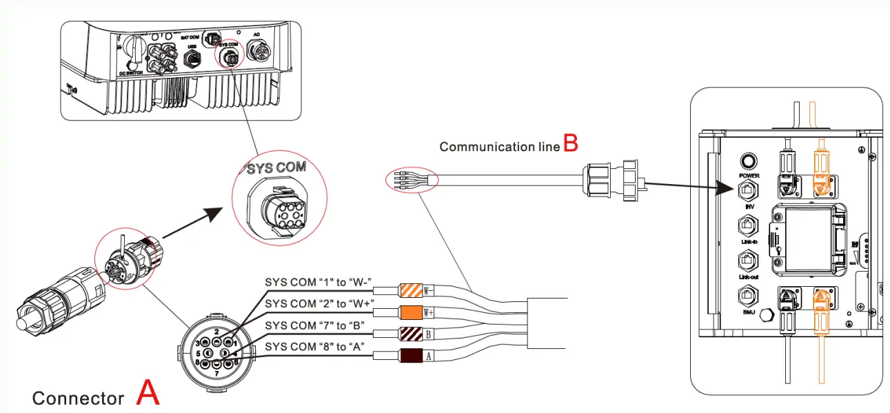
In case the communication cable towards the inverter is missing, you can use a standard RJ45/CAT cable. To connect to the inverter, you will need to connect White Orange to Pin 1, Orange to Pin 2, White Brown to Pin 7, Brown to Pin 8, as shown above, and the associated definition of the numbering of the pins is defined below:
LAN line 1-8 colors as be low:
| PIN | 1 | 2 | 3 | 4 | 5 | 6 | 7 | 8 |
| Color | White orange | Orange | White green | Blue | White blue | Green | White brown | Brown |
| BDC 95045-A1 | MIN TL-XH | ||||
| Silk screen | Terminal serial number | Definition | Silk screen | Terminal serial number | Definition |
| INV | 1 | WAKE-(W-) | SYS COM | 1 | BAT.EN– |
| 2 | WAKE+(W+) | 2 | BAT.EN + | ||
| 7 | RS 485_ 8 (8 ) | 7 | RS 485 B | ||
| 8 | RS 485_A(A) | 8 | RS485 A | ||
Communication interfaces SYS COM Port
The -XH series inverter provides a 8 pin SYS COM Port connector, .The SYS COM Port connector signal distribution and function are shown in t he following table: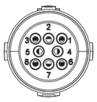
SYS COM Port Pin Definitions
| NO | Definition | NO | Definition |
| 1 | Enable-: Connect BDC enable signal port negative | 5 | RS485A1:Signal for meter |
| 2 | Enable+: Connect BDC enable sign al port positive | 6 | RS485B1:Signal for meter |
| 3 | RS485A2 :Connect Min Shine Bus or third party monitoring equipment | 7 | BAT-B: Connect BOC communication RS485B or CANL |
| 4 | RS485B2:Connect Min Shine Bus or third party monitoring equipment | 8 | BAT-A: Connect B,D C communication RS485Aor CANH |
Procedure
Step 1 Insert the stripped and bared cab le through pressure screw, seal ring , threaded sleeve in sequence, insert cab les into connection terminal according to number indicates on it and tighten the screws firmly. Please try to pull out the wire to make sure the it ‘s well connected .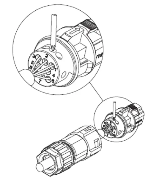
Step 2 Push the threaded sleeve into the socket. Tighten up the cap on the terminal.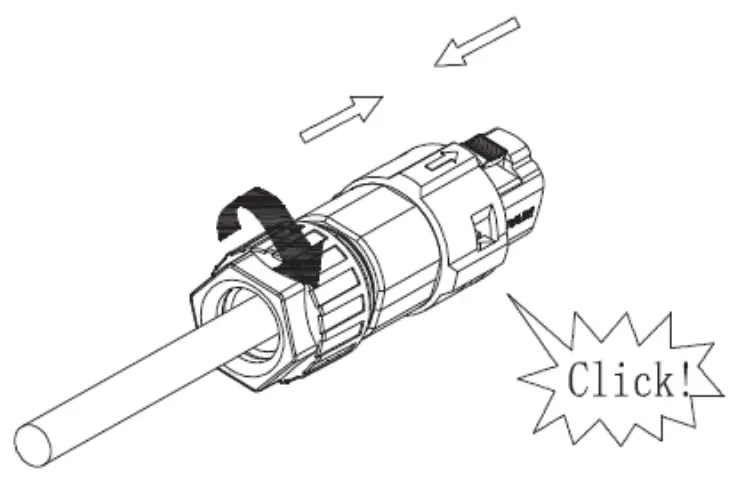
Step 3 Push the threaded sleeve to connection terminal until both are locked tightly on the inverter.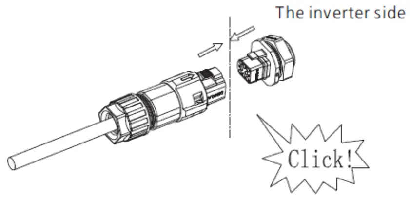
Uninstall signal connector
Step 1 Press the fasteners and pull it out from the inverter.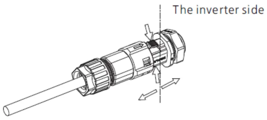
Step 2 Insert the H type tool and pull it out from the socket.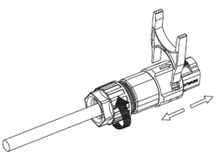
After everything has been properly connected the battery can be turned on. If everything has been properly connected, you will now see information regarding the battery if you go to ‘Storage Parameters’ on the inverter.
Power on battery system:
Turn the circuit breaker to the “ON” state, press the POWER button for 5-6 seconds, wait for the battery system LED light to light up, indicating that the boot is complete.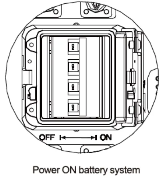
Power off battery system:
Tum the breaker of to ‘OFF” to tum off the entire battery system.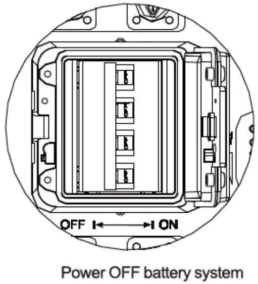
MOD 3000-10000TL-XH
The MOD 3000-10000TL-XH inverters are the higher power three phase counterparts to the MIN-XH. Compatiple with the ARK-XH battery system as well as the upcoming APX battery series.
| BMS controller | BDC 95045-A1 | Supports 3-10 batteries |
| Battery | ARK 2.5H-A1 | Needs at least 3 batteries |
| Battery Base | ARK Battery Base | Necessary to install the batteries on the ground as is recommend. |
| Battery Cable | ARK XH Battery Cable | Every system needs 1 battery cable to connect the inverter to the BMS controller |
| Series cable | ARK 2.5H-A1 Series cable | Only necessary to connect a 2nd set/base of ARK 2.5H-A1 batteries |
| BMS controller | APX 98026 | Supports 1-6 batteries |
| Battery | APX 5.0P HV Battery | Needs at least 1 batteries |
| Battery Base | APX 5.0P HV Battery Base | Necessary to install the batteries on the ground as is recommend. |
| Battery Cable | APX 5.0P HV Battery Cable | Every system needs 1 battery cable to connect the inverter to the BMS controller |
| Series cable | APX 5.0P HV Series cable | Only necessary to connect a 2nd set/base of APX 5.0P HV Battery batteries |
METER COMPATIBILITY
| Brand meter | Type | Sold as | Connection | Suited for delta/split phase | COM adres | RS485A place | RS485B place |
| Eastron | SDM630V2 | TPM | In-Line | Yes | 2 | A | B |
| SDM630CT | TPM-CT | External CT | No | 2 | A | B | |
| Chint | DTSU666 | TPM | In-Line | Yes | 4 | 24 | 25 |
| DTSU666CT | TPM-CT | External CT | No | 4 | 24 | 25 |
Installing ARK 2.5H-A1 Batteries and Connecting the BMS
The connection of the ARK2.5H-A1 batteries is shown below. Make sure that the cables are facing the right orientation. An audible/tactile click indicates a secure connection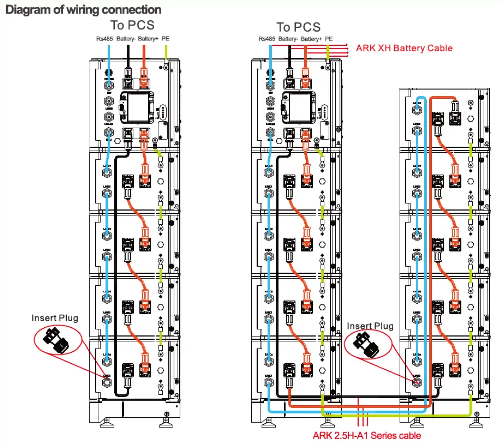
Note: It is not recommended to install a DC circuit breaker between the battery system and the hybird inverter system,
If you want to install a DC circuit breaker with rated working voltage greater than 1 000V and rated working current greater than 63A, do not operate the DC circuit breaker with power on, otherwise the machine may be damaged.
The cable can be removed by pressing the buttons on the side and pulling softly. If placing and removing the cable takes a lot of force, make sure to check the orientation of the cabling, as the connectors are keyed with notches to prevent switches polarities and accidental disconnection during operation.
IMPORTANT: Do not forget to plug in the Insert plug in the last battery. If the Insert plug is not connected, the system will not work correctly.
TIP: If the Insert plug is missing, you can make one yourself by taking the end of a standard RJ45 connector and shorting pins 4 and 5.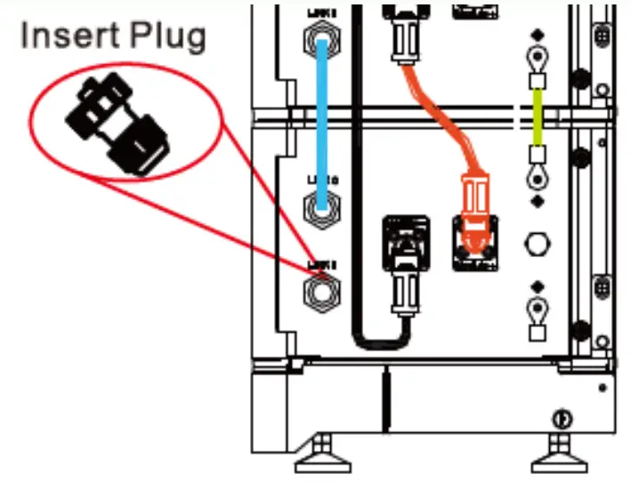
The communication cable from the BMS goes from the BMU port to Link 0 of the first battery. Please make sure all cables are properly inserted.
The INV port on the BMS leads to the SYS COM port of the inverter.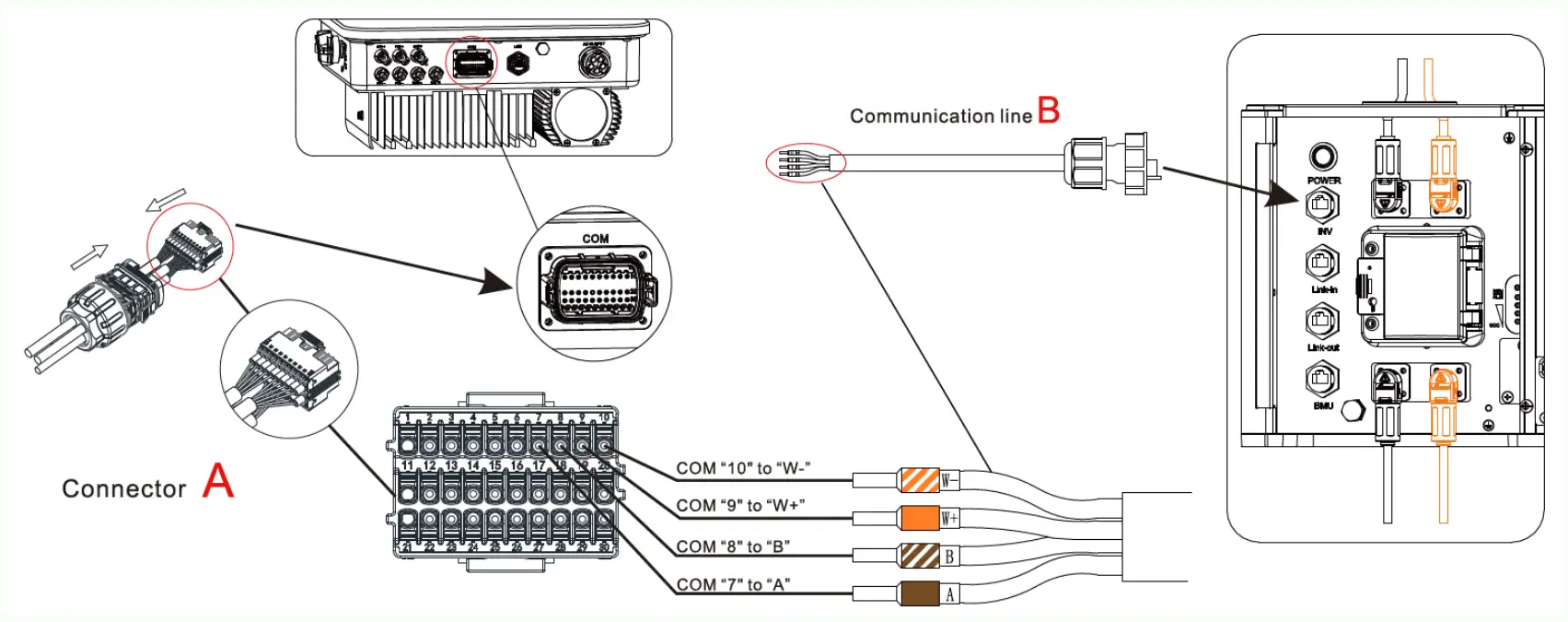
In case the communication cable towards the inverter is missing, you can use a standard RJ45/CAT cable. To connect to the inverter, you will need to connect White Orange to Pin 10, Orange to Pin 9, White Brown to Pin 8, Brown to Pin 7, as shown above, and the associated definition of the numbering of the pins is defined below:
| BOC 95045-A1 | MODTL3-XH | ||||
| Silk screen | Terminal serial number | Definition | Silk screen | Terminal serial number | Definition |
| INV | 1 | WAKE-(W-) | COM | 10 | BAT.EN- |
| 2 | WAKE+(W+) | 9 | BAT.EN+ | ||
| 7 | RS 485_8 (B) | 8 | RS485B2 | ||
| 8 | RS 485_A(A) | 7 | RS485A2 | ||
Meter Installation
For a properly functioning hybrid system, a working meter is vital. The charging and discharging of the batteries are based on the measurements of the meter.
Due to ongoing supply chain challenges, two brands of meters are supplied, Eastron and CHINT, both are functionally identical.
For both the single and three phase inline meters, it is essential that the meter is placed before any of the local load. Easiest way to ensure this is to place it right after the primary AC grid connection.
Do keep in mind that the installation of the meters do differ between the two brands. Below are a summary of their respective manuals
For single phase installations:
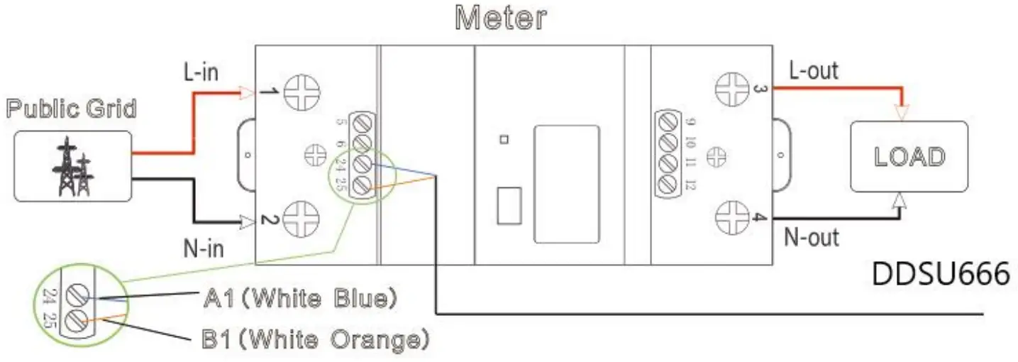
For single phase installations, the meters provided as the Growatt SPM are the Eastron SDM230 and CHINT DDSU666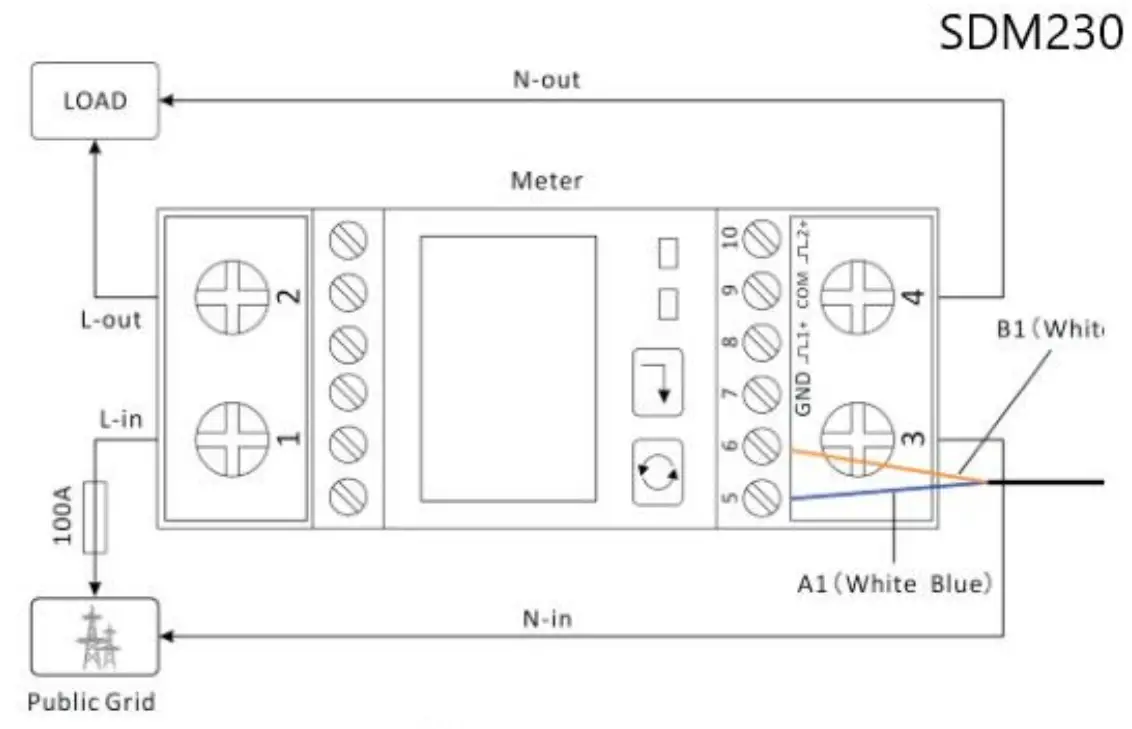
The EASTRON SDM230 the grid is on the left, the load group on the right. Horizontal wiring orientation.
For the CHINT DDSU666 Grid mains on the bottom, on top the load group. Vertical orientation.
The standard cable colours are ‘White Blue: A and White Orange: B’. A and B connect to Pin 5 and 6 on the SYS COM port:
| NO | Definition |
| 5 | RS485A1.Signal for meter |
| 6 | RS48581:Signal for meter |
For three phase installations
For thee phase installations, Growatt supplies the Eastron SDM630 and Chint DTSU666 as the TPM meter.
Keep in mind that for the SDM630 the Load side is on the bottom, while for the DTSU666 the load side in on the topside.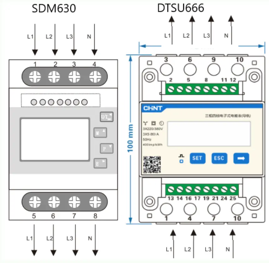
Installation tips for meter connection
When meter and inverter are installed at different places with a distance larger than 15 meters, for instance in the meter box and attic respectively, the following condition is recommended to ensure minimum data loss:
- Try to use an Ethernet cable with as this possible otherwise with shielding. Standard CAT5 cables are not always shielded. If possible, use signal cables or MODBUS cables.
- Always use a twisted pair. In a standard Ethernet cable, this is always a white striped and solid colour cable twisted together.
- Double-check the meter address selection via the Meter Compatibility table.
General Tips For Hybrid Inverters
Here you can find the necessary information for Growatt personnel to understand and analyze the system. Please check the following steps and provide necessary information when contacting Growatt for support.
- Connectivity of the system. Bring the device online with a datalogger. This allows
Growatt personnel to retrieve necessary log file and to perform update remotely. - Provide serial numbers of all components.
- Provide PV voltage, AC voltage measurements.
- Provide individual battery voltage measurements.
- Provide pictures of the full installation.
- Provide the error code information on the LCD display with pictures.
- Provide the time and date when the error first occurs.
After full installation, your COM plugs should look as follows using standard RJ45 (internet) cabling:
For MIN-XH inverters:
- White-orange
- Orange
- Empty / disconnected
- Empty / disconnected
- Meter A (on EASTRON port A+, Chint port 24)
- Meter B (on EASTRON port B-, Chint port 25)
- White-brown
- Brown
Communication interfaces
SYS COM Port
The -XH series inverter provides a 8 pin SYS COM Port connector, .The SYS COM Port connector signal distribution and function are shown in t he following table: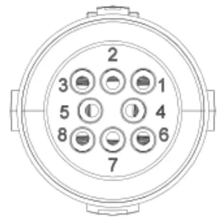
SYS COM Port Pin Definitions
| NO | Definition | NO | Definition |
| 1 | Enable -: Connect BOC enable signal port negative | 5 | RS485A1:Signal for meter |
| 2 | Enable+ : Connect BOC enable signal port positive | 6 | RS485B1:Signal for meter |
| 3 | RS485A2:Connect Min Shine Bus or third party monitoring equipment | 7 | BAT-8 : Connect BOC communication RS485B or CANL |
| 4 | RS485B2:Connect Min Shine Bus or third party monitoring equipment | 8 | BAT-A: Connect BDC, communication RS485Aor CANH |
For MOD-XH inverters
Only the top horizontal row is used. Pins 11 through 30 are not used for general communication or functionalities in Hybrid systems.
1~4 – Empty / disconnected
5 – Meter A (on EASTRON port A+, Chint port 24)
6 – Meter B (on EASTRON port B-, Chint port 25)
7 – Brown
8 – White-brown
9 – Orange
10 – White-orange
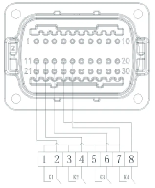
connect to RRCR
| No. | RRCR Description | Active Power |
| 11 | K1-out | 0% |
| 12 | K2-out | 30% |
| 13 | K3-out | 60% |
| 14 | K4-out | 100% |
| 15 | Relays common node | / |
| 16 | / | / |
15 and 16 are not connected ,as for the ccording1 to the customer needs.
| No. | Description | Remarks |
| 1 | +12V | Dry junction : external relay coil interface, power is not more than 2W |
| 2 | COM | |
| 3, | RS485A1 | RS485 communication port |
| 4 | RS48581 | |
| 5 | RS485A3 | Meter communication port |
| 6 | RS485B3 | |
| 7 | RS485A2 | Battery communication port |
| 8 | RS485B2 | |
| 9 | BAT.EN+ | Battery wake-up signal |
| 10 | BAT.EN- | |
| 11 | DRM1/5 | Relay contact 1 input |
| 12 | DRM2/6 | Relay contact 2 input |
| 13 | D·R M 3 / 7 | Relay contact 3 input |
| 14 | DRM4/8 | Relay contact 4 input |
| 15 | REF/GEN | GND |
| 16 | DRM0/COM | / |
| 17 | RS485A4 | Backup box communication |
| 18 | RS485B4 | |
| 19 | CAN- H | CAN communication |
| 20 | ·CAN L |
BMS Error
BMS errors may indicate numerous possible causes. Hence, it is important to ensure that the batteries are under the right working conditions. The follow inspection is to be performed before contacting Growatt.
- The voltage level of the battery modules used. The operating voltage range of the ARK 2.5H-A1 battery is 47.2 – 56.8V. If the battery is under or over voltage, it should not be used anymore.
- The voltage difference between each module should be less than 0.5V. If the voltage difference is higher than 0.5V, the battery may cause errors.
- Make sure that all connections are fastened. Change cable if necessary.
- Install proper grounding in the installation. A potential difference between the BMS and inverter can also cause problems.
- If online monitoring is not available, a local Firmware update can be performed with the appropriate files on a USB stick. Always contact Growatt before any update. Failure to do so may cause damage to the system that is not covered under warranty.
Difference in battery voltage or too deeply discharged batteries
If the difference between the module is too large, or if the batteries have dropped below 48V but still, you can fortunately bring them back to normal by charging them with an external battery charger.
When the module voltage different is too large, or battery voltage is between 36V and 48V, it is possible to charge the battery back to working voltage range by using a lab DC charger power supply. Charger should be set to constant voltage 52V with 5A current. Stop charging when the current reduces to 0.5A.
Measure the voltage after letting the charged battery rest for 2-3 hours. Make sure that the voltage between battery modules is the same, then place them together with the BMS and inverter.
Very important: Pay attention to the polarity! Having the polarity inverted can blow up a lab power supply.