![]() Solar Pump Inverter
Solar Pump Inverter
750W-5500W
User Manual
Information on this Manual
Validity This manual is valid for the following devices:
- Single-phase 220V solar pump inverter, 750W-4000W SPI 750TL-G2, SPI 1500TL-G2, SPI 2200TL-G2, SPI 4000TL-G2
- Three-phase 220V solar pump inverter, 750W-4000W SPI 750TL-LV, SPI 15007L-LV, SPI 2200TL-LV, SPI 4000TL-LV
- Three-phase 380V solar pump inverter, 2200W-5500W SPI 2200TL-HV, SPI 4000TL-HV, SPI 5500TL-HV
Scope
This manual describes the assembly, installation, operation, and troubleshooting of this unit.
Please read this manual carefully before installations and operations.
Target Group
This document is intended for qualified persons and end-users. Tasks that do not require any particular qualification can also be performed by end-users. Qualified persons must have the following skills:
- Knowledge of how a pump inverter works and is operated
- Training in how to deal with the dangers and risks associated with installing and using electrical devices and installations
- Training in the installation and commissioning of electrical devices and installations
- Knowledge of the applicable standards and directives
- Knowledge of and compliance with this document and all safety information
Safety Instructions
WARNING: This chapter contains important safety and operating instructions. Read and keep this manual for future reference.![]() Inspection
Inspection
If missing components or a damaged inverter is found after receiving, please do NOT install or operate it. Otherwise, it may cause human injury or equipment damage.
Installation
- Before installation, please make sure that the voltage range of the PV panel meets the requirement.
- Check if all wires are firmly connected without a short circuit. Otherwise, it will cause equipment damage.
- Do NOT install this inverter under direct sunlight because high temperatures may cause equipment damage.
- Please install the inverter away from inflammable and explosive objectives. Please ensure no liquid can enter the inverter.
- Please install the inverter on a metal non-combustible surface.
![]()
![]()
- CAUTION!! Only qualified personnel can install and operate this inverter.
- To reduce the risk of electric shock, disconnect the power source before making a wire connection. Otherwise, it may cause electrical shock.
- To reduce risk of electric shock, NEVER touch any terminals on electric circuits.
- If the connection cable between the inverter and water pump is more than 50m, please be sure to install a three-phase AC reactor. The inductance value for each phase is about 1mH. Otherwise, the water pump would be easy to be damaged.
Operation
![]()
- Only after the wire connection is complete and put the cover back to the inverter, it entered to do commissioning. Otherwise, it will cause electric shock
- If sunlight is sufficient but little water is pumped, maybe the wires on the motor connection are reversely connected. Please reverse any two wires of them.
- When testing the water pump, be sure to install the water pump at the appropriate water level. Never allow the water pump in dry running. Otherwise, the inverter will activate protection.
Maintenance
![]()
- Only qualified personnel can maintain, repair, inspect the inverter and replace any components.
- It may still contain energy after disconnecting the power source within 5 minutes. Only service after the bus voltage is within safe range.
Symbols
 | Grounding Wire of Equipment |
| AC Value | |
| DC Value | |
| Phase | |
 | Before operating the inverter, please read the instruction. |
| In order to avoid electric shock, breack off the machine with PV terminal and AC terminal for at least 5 minutes, then contact the wire of the machine output terminal and input terminal |
| Warning: when the machine works, the temperature of the metal shell may be very high. |
Introduction
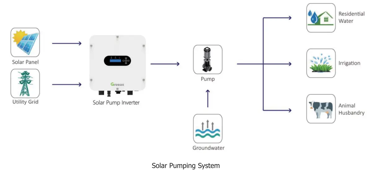
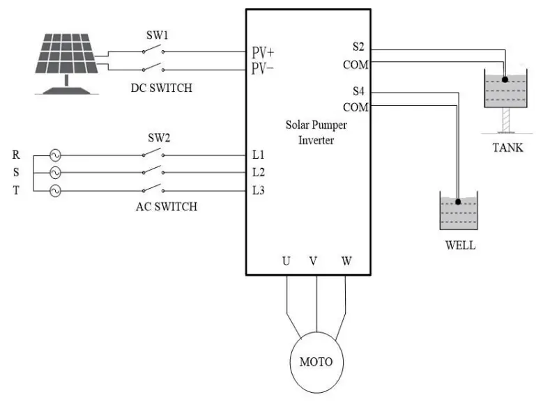
This is a solar pump inverter that allows power to be switched from the AC/DC power obtained from solar panels and gird to the AC power needed to control the pump.
This series solar pump inverter is built-in with a Boost circuit for MPPT solar charger to maximize solar power, and able to set the priority of PV and utility grid input The inverter is suitable for submersible pumps, ground pumps, swimming pool pumps and other pumps using three-phase asynchronous motors.
Features
- Rated power 750W to 5500W
- Inbuilt MPPT solar controller
- Inbuilt BOOST circuit for broadening PV voltage range
- Automatic selection of photovoltaic and AC power
- 1P65 protection level
- Built-in full protection and self-diagnosis
- Soft-start function
- Comprehensive LCD and LEDs display real-time system status
- Remote monitoring through GPRS /4G (optional)
Product Overview
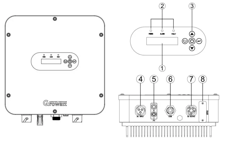
- LCD display
- LED indicators
- Function buttons
- AC input
- PV input
- Water level sensor port
- AC output
- GPRS communication port(optional)
Installation
Unpacking and Inspection
Before installation, please inspect the unit. Be sure that nothing inside the package is damaged. You should have received the following items inside of package:
- The unit x 1
- User manual x 1
- Attachment x 1
Mounting the Unit
Consider the following points before selecting where to install:
- Do not mount the inverter on flammable construction materials.
- Mount on a solid metal surface.
- Avoid direct sunlight. Be sure the environment is shady and cool.
- Be sure to install the inverter into a box with waterproof and dustproof.
- Install this inverter at eye level in order to allow the LCD display to be read at all times.
- The recommended installation position is to adhere to the wall vertically.
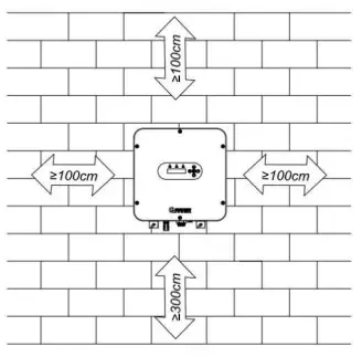
- Be sure to keep other objects and surfaces as shown in the diagram to guarantee sufficient heat dissipation and to have enough space for removing wires.
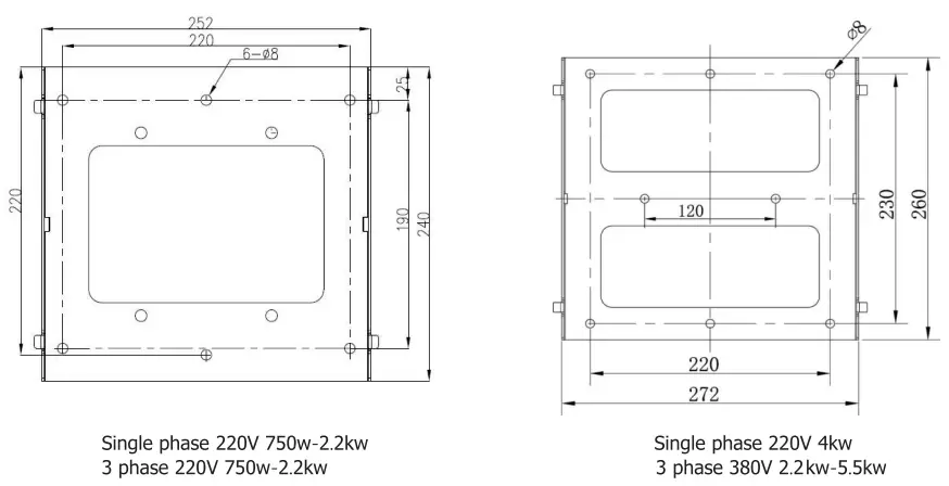
| Single-phase 220V 750w-2.2kw | Single-phase 220V 4kw |
| 3 phase 220V 750w-2.2kw | 3 phase 380V 2.2kw-5.5kw |
SUITABLE FOR MOUNTING ON CONCRETE OR OTHER NON-COMBUSTIBLE SURFACE ONLY.
Install Safety Nut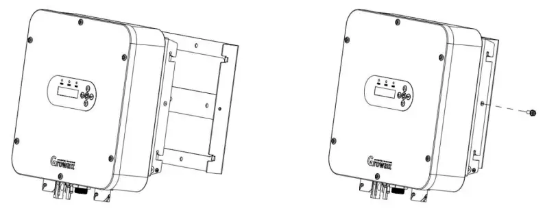
Wiring Introduction
There is AC input,DC input, water level sensor connection terminal, GPRS (optional), and AC output terminal. 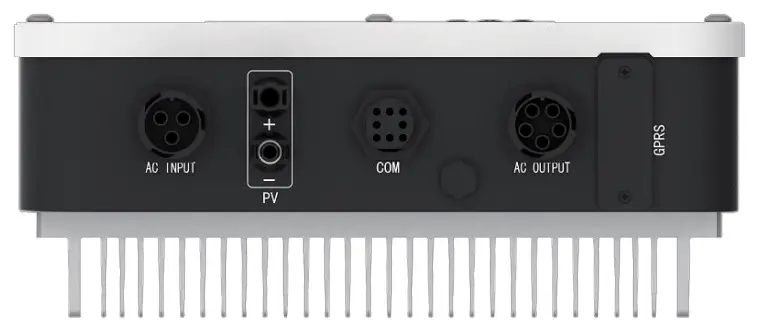
Terminal Introduction
| Socket | Terminal Introduction | Wiring Introduction |
| PV | PV+ | Connect with the positive pole of solar array |
| PV- | Connect with the negative pole of solar array | |
| AC Input | L | Connect with power grid L phase |
| N | Connect with power grid N phase | |
| PE | Connect with protective ground wire | |
| AC Output (3 PH motor connect 1. 2. L) (1 PH motor connect 1. L) | 1 | Connect with motor U phase |
| 2 | Connect with motor V phase | |
| L | Connect with motor W phase | |
| PE | Connect with protective ground wire | |
| COM terminal | 1 | Connect with Sensor 2 of the water tank |
| 2 | Connect with Sensor 2 of the water tank | |
| 3 | Connect with Sensor 1 of the water well | |
| 4 | Connect with Sensor 1 of the water well | |
| 5 | ||
| 6 | / | |
| GPRS connection terminal | 1 | +5V |
| 2 | TXD-232 | |
| 3 | RXD-232 | |
| 4 | GND |
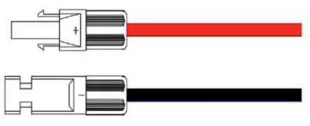
![]() Warning: The places of input sockets of DC positive pole and negative pole of different models are different.
Warning: The places of input sockets of DC positive pole and negative pole of different models are different.![]() Warning: The signal marshaling sequence of AC output sockets of different models are different.
Warning: The signal marshaling sequence of AC output sockets of different models are different.
Assemble DC Connector
Strip the cable 6-8mm,then connect the bare wire core into core tube of the connector.

Crimp contact barrel by using a hex crimping die. Put the contact barrel with striped cable in the corresponding crimping notch and crimp the contact. Insert the core tube into the slot of connection until hearing the sound indicating fit in place. 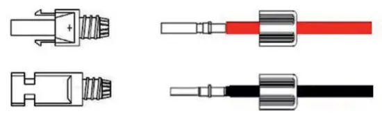
Tighten the nuts to finish the wiring.
![]() Warning: Risk of electric shock! Before shifting the solar panel, disconnect the pump inverter AC and DC. Besides, allow 5-minute internal capacitance discharging.
Warning: Risk of electric shock! Before shifting the solar panel, disconnect the pump inverter AC and DC. Besides, allow 5-minute internal capacitance discharging.
Assemble AC Output Connector
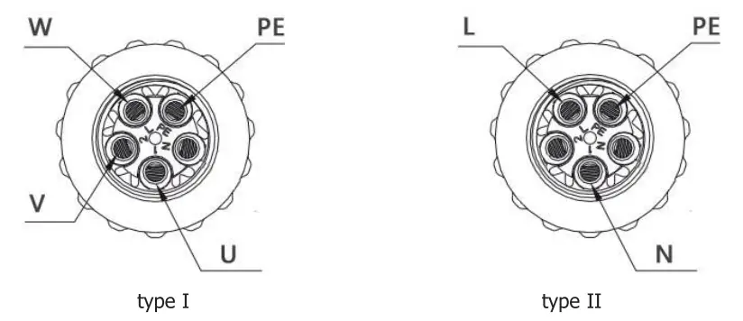
Connection to the AC output side terminal for Growatt SPI 750-5500TL series solar pump inverter, there are two types of AC connector mode.
For type I of 3 phase AC output connector: AC connector 1,2,L, PE gets connection with the pump through 4 wires (U wire, V wire, W wire, and PE wire)
For type II of 1 phase AC output connector: AC connector L, 1, PE gets connection with the pump through 3 wires (L wire, N wire, and PE wire)
 Remove the parts of the AC connection plug from the accessory bag. Guide the pressure screw sealing right, threaded sleeve over the AC cable.
 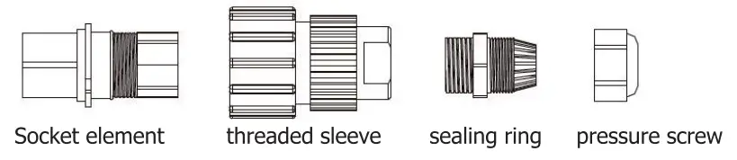 Insert the stripped and bared conductors U, V, W, PE into screw terminals with signs U, V, W, PE on the socket element and tighten the screws.
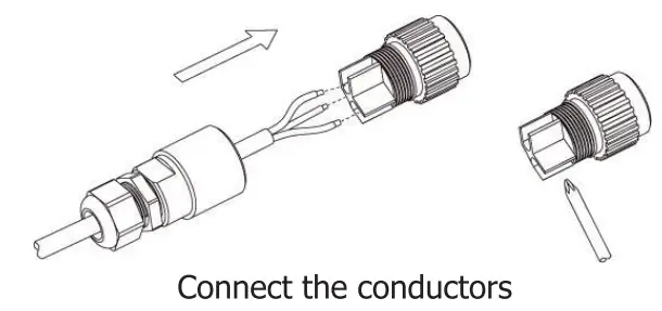
Push the threaded sleeve into the socket element. Screw the pressure screw tightly onto the threaded sleeve. 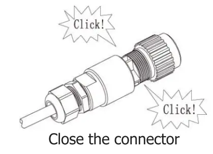
Insert the AC connection plug into the AC connection receptacle on the inverter. 
Assemble AC Input Connector
Remove the parts of teh AC connection plug from the accessory bag. Guide the pressure screw sealing right, threaded sleeve over the AC cable.
Insert the stripped and bared conductors L, N, PE into screw terminals with sign L, N, PE on the socket element and tighten the screws.
Push the threaded sleeve into the socket element. Screw the pressure and screw thightly onto the threaded sleeve.
Insert the AC connection plug into the AC connection receptacle on the inverter.
Wiring of Water Level Sensor
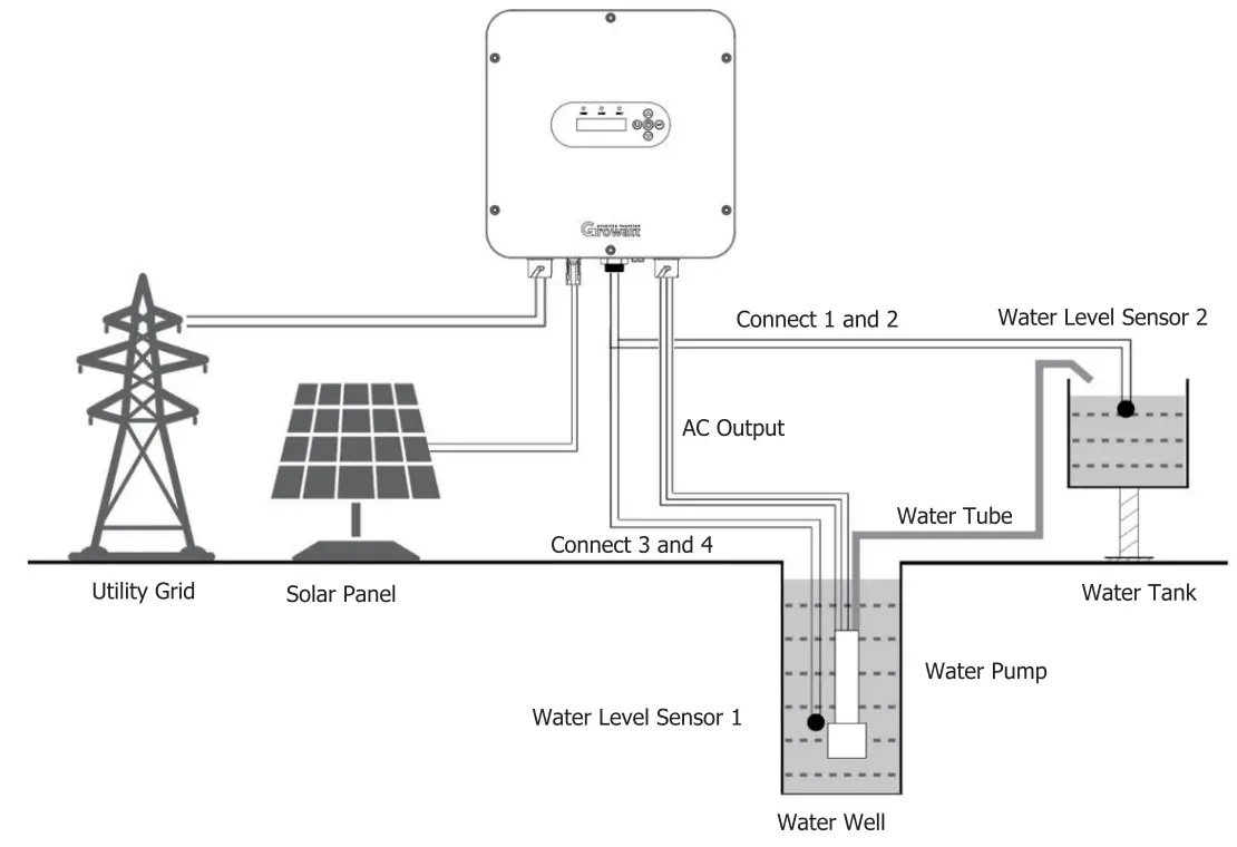
Connection to the COM terminal for Growatt SPI 750-5500TL series solar pump inverter, the water tank connects water level sensor 2, and the water well connects to water level sensor 1. 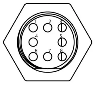
![]() Notice: connect water level sensor 1 and detect water shortage. Respectively connect two signal lines of the sensor with 3 and 4 of COM terminal. When water level sensor 1 detects that the water level of the well is lower than the level set by the sensor, the pump inverter will delay for 5s, then turn off the output protection pump. The water level recovers. Wait for 20s, then the pump inverter re-works normally.
Notice: connect water level sensor 1 and detect water shortage. Respectively connect two signal lines of the sensor with 3 and 4 of COM terminal. When water level sensor 1 detects that the water level of the well is lower than the level set by the sensor, the pump inverter will delay for 5s, then turn off the output protection pump. The water level recovers. Wait for 20s, then the pump inverter re-works normally.![]() Notice: connect water level sensor 2 to detect whether water is full. Connect two signal lines of the sensor with 1 and 2 of COM terminal. When water level sensor 2 detects that the water level of water tank exceeds the level set by the sensor, the pump inverter delays for 5s and turns off the output; when the water level is lower than set level, wait for 20s, then the pump inverter re-starts to work normally.
Notice: connect water level sensor 2 to detect whether water is full. Connect two signal lines of the sensor with 1 and 2 of COM terminal. When water level sensor 2 detects that the water level of water tank exceeds the level set by the sensor, the pump inverter delays for 5s and turns off the output; when the water level is lower than set level, wait for 20s, then the pump inverter re-starts to work normally.
Recommended Diameter of Wire
| Model | Recommended output current(A) | Output voltage(V) | length 30m | length 60m | length’ 90m | length 120m | lengths 150m | length 180m | length(: 210m |
| SPI 750TL-G2 | 5. | 1PH 220V | 1 | 2. | 3. | 4 | 4 | 4 | 6 |
| SPI 15007L-G2 | 10. | 1PH 220V | 2. | 3. | 3. | 6 | 6 | 6 | 6 |
| SPI 2200TL-G2 | 14 | 1PH 220V | 3. | 3. | 4 | 6 | 6 | 6 | 6 |
| SPI 40007L-G2 | 25 | 1PH 220V | 3. | 3. | 4 | 6 | 6 | 6 | 6 |
| SPI 750TL3-LV | 4. | 3PH 220V | 1 | 2. | 3. | 4 | 4 | 4 | 4 |
| SPI 1500TL3-LV | 8. | 3PH 220V | 2. | 3. | 3. | 4 | 4 | 6 | 6 |
| SPI 2200TL3-LV | 10 | 3PH 220V | 2. | 3. | 3. | 6 | 6 | 6 | 6 |
| SPI 4000TL3-LV | 16 | 3PH 220V | 2. | 3. | 3. | 6 | 66 | 6 | |
| SPI 2200TL3-HV | 6. | 3PH 380V | 2. | 3. | 3. | 6 | 66 | 6 | |
| SPI 4000TL3-HV | 10. | 3PH 380V | 2. | 3. | 3. | 6 | 66 | 6 | |
| SPI 5500TL3-HV | 14 | 3PH 380V | 3. | 3. | 4 | 6 | 6 | 6 | 6 |
| Units: mm2 | |||||||||
![]() Notice: The environment temperature for the above-recommended wire dimension should be 50°C.
Notice: The environment temperature for the above-recommended wire dimension should be 50°C.![]() Notice: Large-power wall-mounted model uses multiple-channel DC input. The dimension of the DC wire of each channel shall be selected according to the above table.
Notice: Large-power wall-mounted model uses multiple-channel DC input. The dimension of the DC wire of each channel shall be selected according to the above table.
Operation
Display Panel
Solar pump inverter uses LCD operation panel. The operation panel is shown in the figure, including 3 LED lights, LCD display and 5 keys.
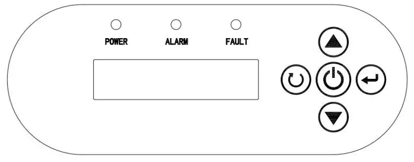
| Indicator and Key | Name | Function Introduction | |
| POWER | System running indicator | Green | LED on, the inverter is running |
| ALARM | Warning indicator | Yellow | The LED on, warning, or in terminal mode |
| FAULT | Failure indicator | Red | LED on, system failure |
 | Operation / Stop Key | 1. Press for a short time, then the inverter starts control; 2. Press for 2s, then inverter stops control. | |
| Confirm / Programming Key | 1. Press for a short time to enter programming mode. After altering the parameter, “press for a short time” to confirm the alteration 2. Press for 2s to enter the programming menu. | ||
| Increment Key | 1. When the control parameter displays state, increase parameter number or parameter value; 2. When operation displays data state, according to operation mode, increase output frequency or display current operation data. | ||
| Decrement Key | 1. When the control parameter displays state, press for a short time to decrease parameter number or parameter value. 2. When operation shows data state, according to operation mode, decrease output frequency or display current operation data. | ||
| Return Key | Return the initial display | ||
LCD Display Information
The LCD display information includes operation data, control parameters, and historical parameters. The information on the display will be switched in turns by pressing the UP/DOWN key. The selectable information will be switched as below.
| Description | Display |
| Output frequency of the inverter | Running Frequency= 50.00Hz Fr eg Run |
| Set the frequency of the inverter | Set Frequency=50.00Hz Fr eg Set |
| Input voltage of the inverter | Input PV voltage=548V PV Volt. |
| The output voltage of the inverter | Output voltage=379V Output Volt. |
| The output current of the inverter | Output current=0.7A Output Curr. |
| The relative value of rated power | Power capacity=79.1% Capac.it9 |
Parameters Setting
- Work Mode Setting
The inverter includes three work modes: manual work mode, fully-automatic terminal work mode, and GPRS work mode (optional). The default mode is fully-automatic terminal work mode.
a. Manual work mode: menu P00. Setting P00.01=0. Press![]() the inverter stop working. key to operate. Press
the inverter stop working. key to operate. Press![]() key for 2s, then
key for 2s, then
b. Fully-automatic terminal work mode: menu P00. Setting P00.01=1. When sunlight is strong enough, the inverter will automatically trace the maximum PowerPoint.
c. GPRS work mode (optional): menu P00. Setting P00.01=2. Under this model, combined with a cellphone number, send messages to set startup, shutdown, parameter inquiry, etc.
| Description | Display |
| Initial status: non-historical data display | |
| Enter the main parameter modification interface for long press 2s for Entering key | P00 parameter group, Work Mode group Work Mode |
| Press Enter key | P00.01 subparameter group Work Mode |
| Press Enter key | 00.01, value =1 (Default), terminal work mode Work Mode |
| Use the Down key | P00.01, value =0, manual work mode Work Mode |
| Press Enter key | Present: Set OK! Work Mode |
2. Rated parameters setting for the motor
Before setting the parameters, please make sure all the wiring is correct.
a. Setting P00.01=0. Command code channel is keyboard manual mode instruction.
b. Set water pump nameplate parameters: P02.01 motor rated power value; P02.02 motor rated frequency value; P02.04 motor rated voltage value; P02.05 motor rated current value.
c. After finishing the parameter setting of the water pump, set P00.01=1. The operation code channel is altered as origin solar Panel mode instruction.
See as the following figures. (e.g. 5.5 KW inverter drives 4.0 KW water pump)
| Description | Display |
| Press Enter key | Fred Run 50.00Hz |
| Long press the ON/OFF key | Power off |
| Enter the main parameter modification interface for long press 2s on the Entering key | P00 parameter group, Work Mode group Work Mode |
| Press the UP key | P02 parameter group, Rated Parameters group Motor Par. |
| Press Enter key | P02.01 code channel, Rated Power setting Rating Pwr. |
| Press Enter key | Rated power=5.5KW Rating Pwr. |
| Use the Up | Rated power=4.0KW Rating Pwr. |
| Press Enter key | Present: Set OK! Work Mode |
| Press Enter key | P02.01 code channel, Rated Power setting Rating Pwr. |
| Press the UP key | P02.0 5 code channel, Rated Current setting Rating Curr |
| Press Enter key | Rated Current=10.0A Rating Curr |
| Use the Up | Rated Current=10.3A Rating Curr |
| Press Enter key | Present: Set OK! Work Mode |
| Press Enter key | P02.05 code channel, Rated Current setting Rating Curr |
| Press ESC key | P02 parameter group, Rated Parameters group Motor Par. |
| Press Down key | P00 parameter group, Work Mode group Work Mode |
| Press Enter key | P00.01 subparameter group Work Mode |
| Press Enter key | 00.01, value =0, manual work mode Work Mode |
| Press UP key | P00.01, value =1, terminal work mode Work Mode |
| Press Enter key | Present: Set OK! Work Mode |
| Press Enter key | Rated Frequency=SOHz Rating Free |
| Turn off the DC switch and AC switch, waiting for the LCD display to off, then turn on the DC switch, the inverter will auto-start to drive the pump(5.5kW) |
After finishing all parameter settings, turn off the DC switch and AC Switch. After display screen is OFF for 5 minutes, turn on AC output. Then turn on DC switch and AC switch. Wait for the 60s, the machine will operate automatically.
![]() Warning: Do not change parameters at random, otherwise the system might not work normally.
Warning: Do not change parameters at random, otherwise the system might not work normally.
Function Parameters
| SN | Name | Scope | Introduction | Default Value |
| P00.01 | Operation code channel | 0-2 | 0: keyboard operation code channel (LED is off) 1:terminal operation code channel (LED flashes) 2:communication operation code channel (LED is solid on) | 1 |
| P00.03 | MAX.Output frequency | P00.04-400.00 | Setting the maximum output frequency | 50.00Hz |
| P00.04 | MAX.running frequency | 0.00- P00.03 | Setting the maximum running frequency | 50.00Hz |
| P00.18 | Function restore parameter | 0-1 | 0: No operation 1: Restore the default value | 0 |
| P02.01 | Rated power of asynchronous motor | 0.1 – 3000.0 | 0.1 – 3000.0kW | Model confirmation |
| P02.02 | Rated frequency of asynchronous motor | 0.01 – P00.03 | 0.01 – P00.03 | 50.00Hz |
| P02.04 | Rated voltage of asynchronous motor | 0 – 1200 | 0 – 1200V | Model confirmation |
| P02.05 | Rated current of asynchronous motor | 0.8 – 6000 | 0.8 – 6000A | Model confirmation |
Troubleshooting
The inverter has complete protection. When a failure occurs, the inverter will take protective measures. The general protection is to stop the motor from running and forbid it to restart within a certain period.
| Code | Description | Possible Reasons | Countermeasures |
| Power off | No failure | W | W |
| Inc OW Dec OW Con OVP | Overvoltage | The input voltage is too high | Check the voltage of solar array |
| Vbus low | Undervoltage | 1. Input voltage is too low; 2.11Iumination intensity is too weak | Check the voltage of the solar array |
| Inc OCP Dec OCP con OCP | Overcurrent | 1. A load of the pump is too large; 2. The voltage of the solar array is too low; 3. The motor wiring is too long | 1. Replace for a smaller pump; k 2.Chec3.The short voltage of solar array; en the wiring between inverter and motor |
| Overload Tel | The water pump is an overload | Load is too large | Decrease maximum operation frequency |
| Overload VVVF | Inverter is overload | The inverter load is too large | Decrease power grade of water pump |
| IGBT shortcut | Module overcurrent | Output short circuit or grounding module damage | 1. Check the wiring 2. Get after-sells support |
| Inv Overtemp | Module is over-temperature | 1.Air flue is blocked 2. Environment temperature is too high 3. The time of overload running is too long. | 1. Clean air flue or improve ventilation 2. Degree the environment temperature |
| REC Overtemp | The module is over- temperature | ||
| Scarce Phase-Out | default Output phase | Equipment or circuit damage | Get after-sells support |
| Shortcut GND 1 | Grounding short circuit | The output line may be connected with ground | Check the wiring |
| Curr Test Fault | Current detection failure | 1. The control board connection is in poor contact 2. The hall component is damaged The magnifying circuit is abnormal | Get after-sells support |
| Lack load | The water pump conducts a “dry- operation” | The water pump’s connection wires are all open circuits. The water pump does not match the inverter | 1. Check water level. 2. Check whether the water pump wiring condition and water pump power meet the requirements of inverter capacity |
| No Water | Water shortage | Water shortage warning | When water is provided, it can recover automatically |
| Water-Full | Water full | Water full warning | When the water level decreases, it can recover automatically |
| Com Fault | Communication failure | Device or circuit damage | Reset Get after-sells support |
![]() Warning: Try to find out the failure reason before your try reset. If it can’t reset or suffers failure again after reset, please try to find out the reason first. Continuously resetting could damage the inverter.
Warning: Try to find out the failure reason before your try reset. If it can’t reset or suffers failure again after reset, please try to find out the reason first. Continuously resetting could damage the inverter.
Specifications
| MODE | SRI 750TL -G2 | SPI 15007L -G2 | SPI 22007L -G2 | SPI 4000TL -G2 | SPI 750TL3 -LV | SPI 15007L3 -LV | SPI 2200TL3 -LV | SPI 40007L3 -LV | SPI 2200TL3 -HV | SPI 400073 -HV | SPI 55007L3 -HV |
| DC INPUT | |||||||||||
| Max.DC voltage | 450V | 450V | 800V | ||||||||
| Starting voltage | 80V | 80V | 220V | ||||||||
| Recommended MPPT voltage | 100- -400V | 100- 400V | 220-750V | ||||||||
| Max. DC current | 9A | 12A | 12A | 20A | 9A | 12A | 12A | 20A | 12A | NA | 20A |
| Number of input channels | 1 | 1 | 1 | 2 | 1 | 1 | 1 | 2 | 2 | 2 | 2 |
| AC INPUT | |||||||||||
| Input voltage | 1PH 220-240V (-15% —+10%) | 1PH 220-240V (-15% — +10%) | 3P1-1 380V (-15% — +10%) | ||||||||
| Rated input current | 9.5A | 16A | 24A | 38A | 9.5A | 16A | 24A | 38A | 6A | 14A | 20A |
| Input frequency | 47–63 Hz | ||||||||||
| AC input terminal | L,N, PE | L,fil , PE | R,S,T,PE | ||||||||
| AC OUTPUT | |||||||||||
| Rated output power | 750W | 1500W | 2200W | 4000W | 750W | 1500W | 2200W | 4000W | 2200W | 4000W | 5500W |
| Rated output current | 5.1A | 10.2A | 14A | 25A | 4.2A | 7.5A | 10A | 16A | 5.5A | 9.5A | 14A |
| Output wiring mode | 1P1L | 3P3L | 3P3L | ||||||||
| Output voltage | 0-220V | 0-220V | 0-380V | ||||||||
| Output frequency | 0-50/60Hz | ||||||||||
| CONTROL PERFORMANCE | |||||||||||
| Control mode | V/F | ||||||||||
| Motor type | Asynchronous motor (1PH 220V) | Asynchronous motor (3PH 220V) | Asynchronous motor (3PH 380V) | ||||||||
| PROTECTION FUNCTIONS | |||||||||||
| Output overcurrent | YES | ||||||||||
| Output overload | YES | ||||||||||
| Output short-circuit | YES | ||||||||||
| Dry/Overflow protection | YES | ||||||||||
| OTHERS | |||||||||||
| Display | LCD | ||||||||||
| Communication | GPRS/WIFI (OPTION) | ||||||||||
| Certificate Standard | CE | ||||||||||
| Dimensions (NxDxH), mm | 370x335x135 | 450x 365 x150 | 370 x 335x 135 | 450 x 365x 150 | |||||||
| Net weight, kg | 10. | 17. | 10. | 17. | |||||||
| Operation temperature range | -25-60°C (with derating above 45°C) | ||||||||||
| Environmental Protection Rating | IP65 | ||||||||||
| Cooling | Natural cooling | ||||||||||
| Altitude | 3000m (with derating above 2000m ) | ||||||||||
| Relative humidity | 0-100% | ||||||||||


