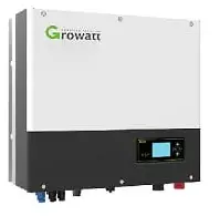
GROWATT SPH3000 Hybrid Inverter
Overview
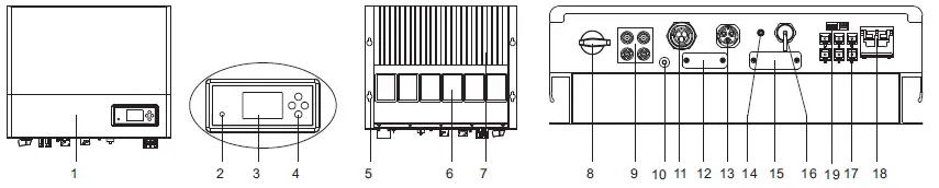
- Front panel
- Double color LED
- LCD screen
- Push button
- Wall hole
- Magnetic devices
- Heat sink
- PV switch
- PV connector
- Grounding screw
- AC grid connector
- Reserved hole
- EPS connector
- Antenna hole
- RS232 port
- USB port
- Communication ports
- Battery power terminal
- DIP and Dry connector
NOTE:
- If SP-CT is used to communication with hybrid inverter. Please plug in antenna in (14).
- Function introduction of communication ports (17) in the follow
NOTE:
- This file will be updated from time to time due to product upgrades or other reasons. Unless otherwise agreed, this document is intended as as a guide only. All information and suggestions do not constitute an express or implied warranty. The final interpretation of the content is at Growatt.
- This document is for quick guidance installation only. For details, please refer to the User Manual.
- Machine damage caused by failure to follow the content is not covered by the warranty.
Installation
System Overiew
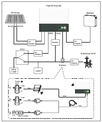 Note: The installation of this hybrid system needs to comprehensively consider the position of the battery and the power collector.
Installation requirements
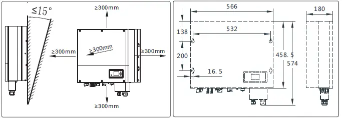
Wall mounting
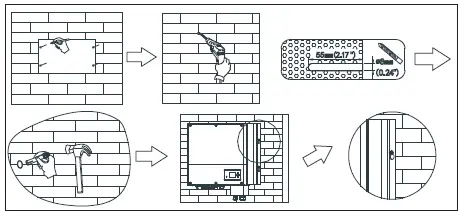
Notes: Be careful : Avoid water and electricity pipes when punching holes in the wall, otherwise it may be dangerous.
Monitoring device installation
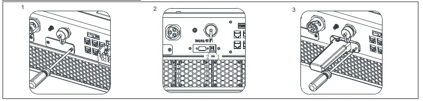
Follow the installation steps:
- Remove the RS232 waterproof cover.
- Switch off all the DIP next to RS232
- Plug in the communication module.
Connecting cables
Please prepare the cable before connecting as follows.
| Number | Cable name | Type | Recommend module | Notice: 1.Lithium battery has its own power line and communication line, so use them. 2 . H y b r i d i n v e r t e r i n c l u d e t h e b a s i c communication line. So use them directly. 3.Please make sure all the switches off before connection. For your safety, please do not operation when power on. |
| 1 | grounding cable | Single multi-core yellow-green copper cable | Cable diameter≥AWG10 | |
| 2 | AC output cable | Two or three different color multi-core copper cables | Cable diameter≥AWG10 | |
| 3 | PV input cable | Photovoltaic dedicated cable( such as PV1-F) | 4mm² – 6mm² | |
| 4 | Battery power cable | Red and black multi-core copper | Cable diameter≥AWG6 | |
| 5 | Other communication cable | CAT5E | / |
Grounding
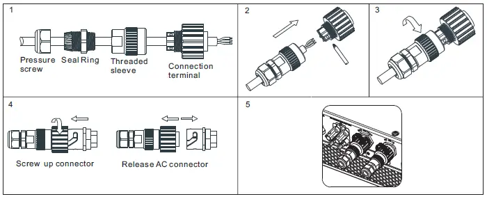
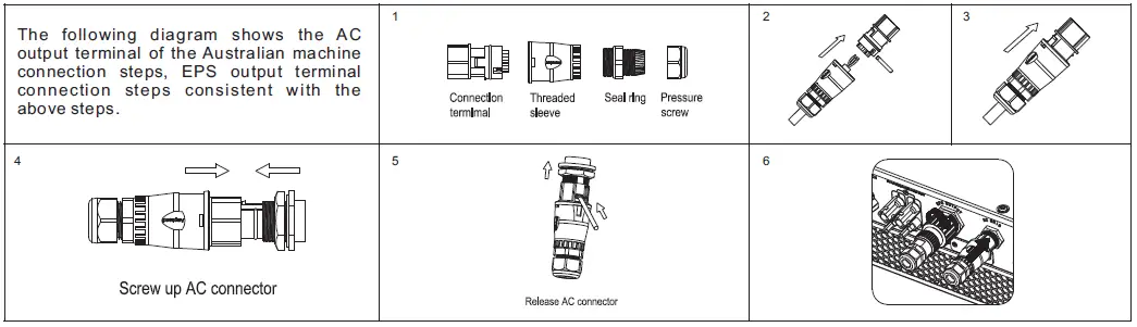
AC GRID and EPS output connection
DC connection
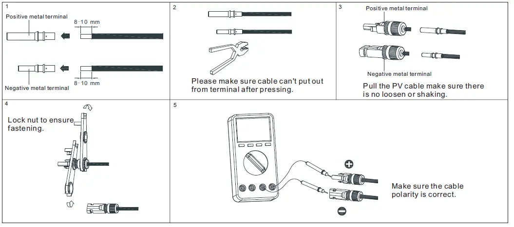
PV input terminal installation
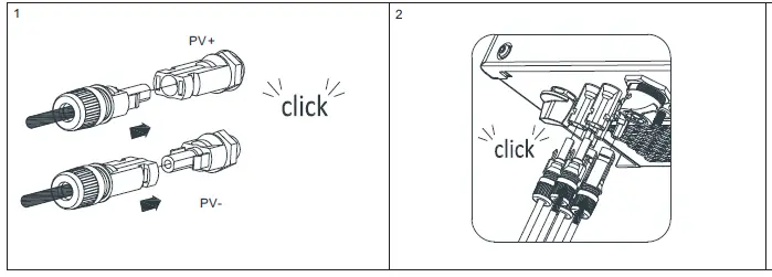
Plug in PV terminal
Notes:
- P l e a s e m a k e s u r e t h e P V i n p u t voltage/current not beyond the specification before plug in.
- When installing the PV terminal, pay attention to the distinction between the positive and negative terminals and the one-t o – o n e c o r r e s p o n d e n c e b e t w e e n t h e terminals and hybrid inverter.
- When the terminal is docked, there is a click sound. After the terminal is docked, gently pull the PV cable to observe whether the terminal is shaking or not.
Battery power line connection
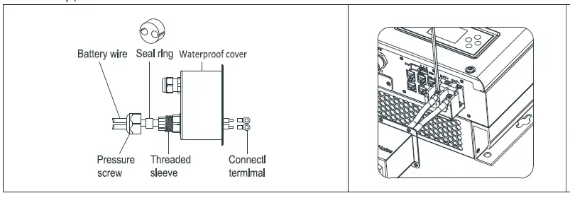
Installation steps as follow:
- Pass the battery power cables through the tightening nut, waterproof rubber plug and waterproof cover.
- Press OT terminal at the end of cables.
- Connect the power cable to hybrid inverter. Be careful the polarity.
- Be careful not to tighten the tightening nut at this time. After all the communication cables are installed, tighten them together.
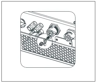
Communication cables installation
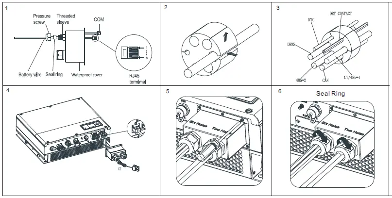 When all the communication lines are installed, push the waterproof cover into the bottom, lock the screws fixed to the frame, and finally lock the waterproof cap.
Post-installation check
| Number | Acceptance Criteria | Number | Acceptance Criteria |
| 1 | Hybrid inverter is installed correctly and firmly | 2 | shineWiFi-S or shinelink or GPRS is installed correctly and firmly. |
| 3 | Cable wiring is reasonable, meets the requirements, no broken skin, etc. | 4 | The ground wire confirms the connection and is reliable. |
| 5 | All switches off | 6 | All wires are correct and securely connected. |
| 7 | Cable tie port trimming, no sharp corners, etc. | 8 | All exposed terminals are well protected, no vacant ports. |
| 9 | Pay attention to packing all the residual materials. |
On off hybrid inverter
Notes: Before power on, please make sure all of the voltage and current are in the range of specification of hybrid inverter. Otherwise it will be damage to hybrid inverter.
Follow are the steps of turn on actions:
- Turn on the switch between Grid and hybrid inverter.
- Turn on battery and the switch between battery and hybrid inverter.
- Turn on PV switch
- If need to setup hybrid inverter. Please turn to user manual of hybrid inverter for detail description.
- The shutdown steps are opposite to the above order.
Status of hybrid inverter
Customer can read more information by push button. Follow are the instruction of button and LED.
| Mark | Description | Explanation | |
 | Push-button | Operation of display screen and set system | |

| Status symbol of SPH | Green light on | SPH run normally |
| Red light on | Fault state | ||
| Green light blinking | 1.Alarm state | ||
| Red light blinking | 2.Software updating | ||


