Growatt AT-5000ES Solar Inverter

Introduction
The auto-transformer(AT-S000ES) is used for backup power only, its input connects to the AC side of the inverter, for the purpose of providing the split phase power to the loads.
The AT-S000ES in the System
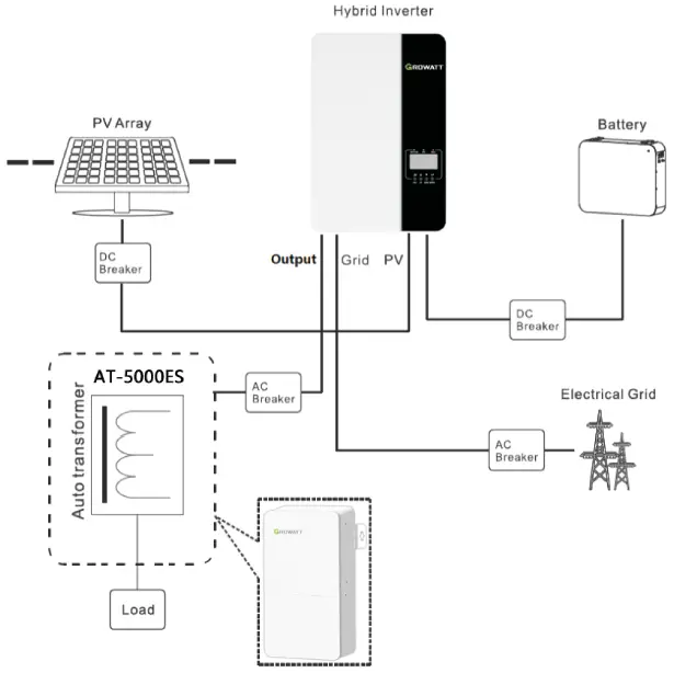
As shown in the picture, the input side of AT-S000ES is connected to the output of the inverter, and the output side is connected to the critical load. There is a transformer in AT-S000ES, it can transfer 240V to 120V /240V split phase to provide the power to load.
Configuration
| Model name | AT-SOOOES |
| Input Rated Voltage | 240/208V |
| Input Rated Frequency | 50/60Hz |
| Input Rated Current | 21A/24A |
| Load Rated Voltage | 120/240V or 104/208V (split phase) |
| Load Max. Continued Current (L-L) | 21A/24A |
| Load Max. Continued Current (L-N) | (21A/24A)*2 |
| Load Rated Power (L-L) | S000VA |
| Load Rated Balanced Power (L-N) | 2500VA*2 |
| Load Max. Unbalanced Power (L-N) | 2500W |
| Cooling Concept | Natural |
| Ingress Protection | IP 20 |
| Installation | Wall Mountable |
| Operation Ambient Temperature | -25°C~ +50°((-13 to+122°F) |
| Weight | 13.5kg/30Ib |
| Size | 385*210*1 OSmm/15.16*8.27*4.13in |
General Information Parts List
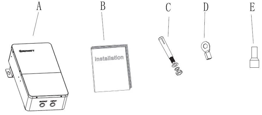
| Part List | |||||
| Item | Item Name | Qty | Item | Item Name | Qty |
| A | AT-S000ES (Auto-transformer) | D | O -type terminal | 2 | |
| B | User Manual | E | Cold pressed | 6 | |
| C | Anchor Bolt | 2 | |||
Tools
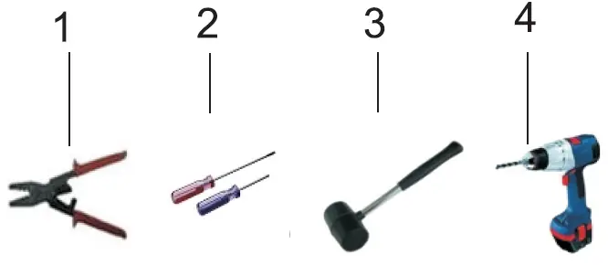
| NO. | Description |
| Press terminal connector | |
| 2 | Screwdriver |
| 3 | Knock explosion bolt |
| 4 | Drill holes on the wall |
Wall Mount Installation
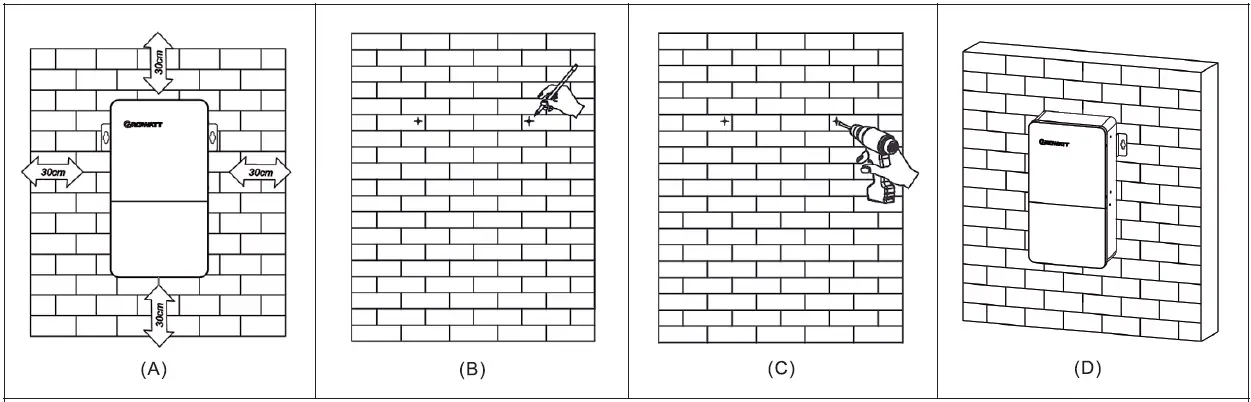
- A) Please reserve the space of 300mm (11.8in) from AT-SO0OES.
- B) Place the ruler horizontally on the wall and mark the position of 2 holes for screws.
- C) Remove the ruler and drill 2 holes were marked, Drill holes with cp10 drill Depth: at least 40mm (1.575in).
- D) First knock the expansion pipe into the hole with a Rubber hammer and then place the AT-S0O0ES align with the marked position on the wall. Last, screw the self-tapping screwing into the expansion pipe.
Open the AT-5000ES
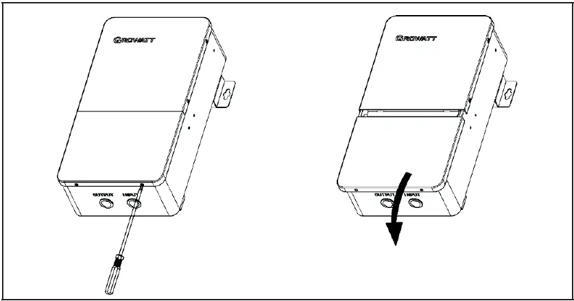
As shown in the picture, please use the screwdriver to get out the 2 screws at the bottom of the AT-S000ES, then pull back to take out the bottom cover.
Wiring Connection
Wires Making
- The wires below are needed before installation.

Cable description Cable Type Conductor Cross sectional Area Range Source Input power cable
1. Use cables that can withstand 90°C (194°F) or 105°C (221°F).
2. Three single-core outdoor copper cables (L, N, PE)
L, N: 10-6AWG PE: 10-6AWG
Purchased by customer
Output power cable
1. Use cables that can withstand 90°C (194°F) or 105°C (221°F).
2. use four single-core outdoor copper cables (L1, N, L2, PE).
L, N, L2: 10-6AWG PE: 10-6AWG
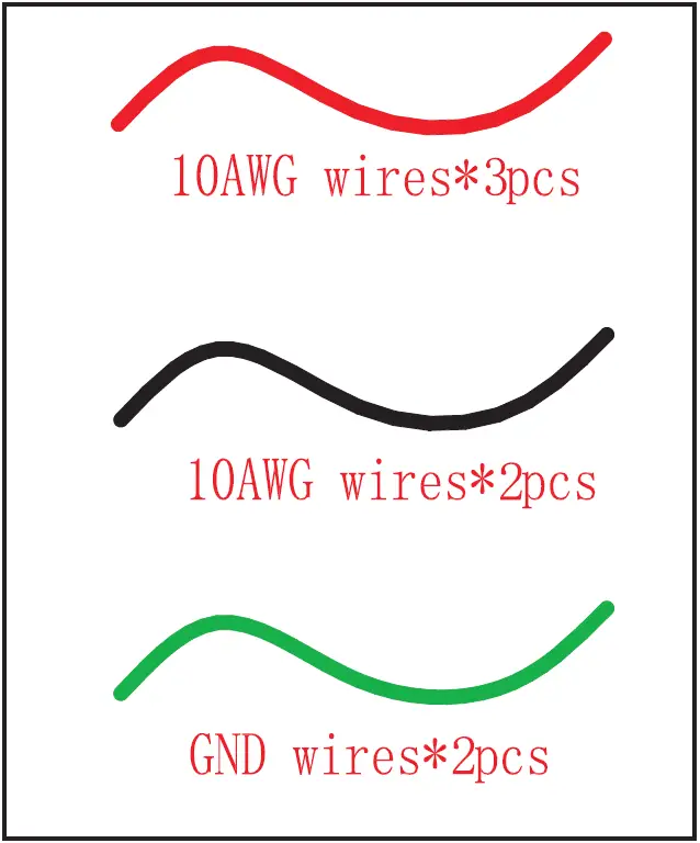
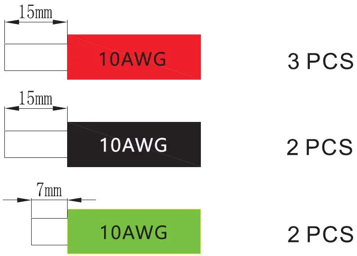
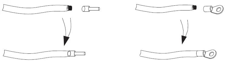
Purchased by customer - Use the diagonal plier to trip 15mm of insulation from one side of the 1 0AWG wires. Use the diagonal plier to trip one side of the GND wire about 7mm.

- There are two types of wire that need to be machined, please check ref to 9.1 wired diagram. The following two type of wires are show below (type1 is used for power line connection, type2 is used to ground connection):

Input Wires Connection
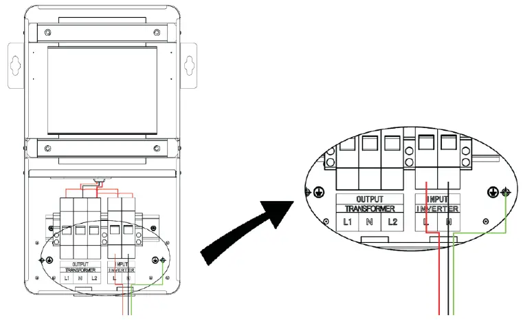
Use the screwdriver to remove the nut on the input terminal strip, and the red 1 0AWG short wire ends were inserted into the input port L, and the black 1 0AWG short wire ends were inserted into the input port N. Use a screwdriver to lock the ground wire on the earth bus bar.
Output Wires Connection
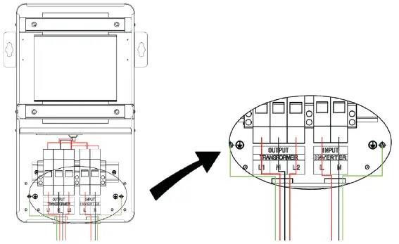
Use the screwdriver to remove the nut on the output terminal strip, and the red 1 0AWG short wire ends were inserted into the output ports L 1 and L2, The Black 1 0AWG short wire ends were inserted into the output port N. Use a screwdriver to lock the ground wire on the earth bus bar.
Checking
Please make sure that all wiring in the AT-5000ES is tightened.
AT-5000ES USA e methods
After connecting the AT-5000ES internal wire, close the cover and the input end of the AT-5000ES is connected with the output of the inverter, the output end of the AT-5000ES access load. Run the system, and loaded into normal operation.
Troubleshooting
Please turn off the inverter and open the AT-5000ES cover, and check the input wiring and the output wiring properly.
Caution
- Please use the equipment within the scope of the specification. Excessive current or voltage may cause device damage.
- To avoid personal injury due to energy hazards, remove wristwatches and jewelry when repairing. Use tools with insulated handles.
- The rated power of the secondary side L 1-N and L2-N could be up to 5KVA respectively, and the power difference between the two split phases can not exceed 2.5KW.
- Don’t connect N of AT-5000ES output together with N of input.
- Don t connect N of AT-5000ES to PE of AT-5000ES or PE of the grid.
- Repair is to be performed only by qualified technical personnel authorized by the manufacturer.
- The rated balanced power(L-N)means the Load of L 1-N and L2-N is equal.
- The rated unbalanced power(L-N)means the load of L 1-N and L2-N is different.


